US6147448A - Piezolelectric porcelain step-up discharge tube - Google Patents
Piezolelectric porcelain step-up discharge tube Download PDFInfo
- Publication number
- US6147448A US6147448A US09/113,970 US11397098A US6147448A US 6147448 A US6147448 A US 6147448A US 11397098 A US11397098 A US 11397098A US 6147448 A US6147448 A US 6147448A
- Authority
- US
- United States
- Prior art keywords
- discharge
- piezoelectric
- discharge tube
- tube
- vacuum tube
- Prior art date
- Legal status (The legal status is an assumption and is not a legal conclusion. Google has not performed a legal analysis and makes no representation as to the accuracy of the status listed.)
- Expired - Fee Related
Links
- 229910052573 porcelain Inorganic materials 0.000 title claims abstract description 23
- 239000000463 material Substances 0.000 claims abstract description 10
- 239000004020 conductor Substances 0.000 claims abstract description 8
- 238000007599 discharging Methods 0.000 claims abstract description 6
- 239000000126 substance Substances 0.000 claims abstract description 4
- -1 tin halide Chemical class 0.000 claims description 2
- 230000000694 effects Effects 0.000 description 6
- QSHDDOUJBYECFT-UHFFFAOYSA-N mercury Chemical compound [Hg] QSHDDOUJBYECFT-UHFFFAOYSA-N 0.000 description 5
- XKRFYHLGVUSROY-UHFFFAOYSA-N Argon Chemical compound [Ar] XKRFYHLGVUSROY-UHFFFAOYSA-N 0.000 description 4
- 239000003574 free electron Substances 0.000 description 4
- 230000010355 oscillation Effects 0.000 description 4
- 239000007789 gas Substances 0.000 description 3
- 229910052786 argon Inorganic materials 0.000 description 2
- QVQLCTNNEUAWMS-UHFFFAOYSA-N barium oxide Chemical compound [Ba]=O QVQLCTNNEUAWMS-UHFFFAOYSA-N 0.000 description 2
- 239000013078 crystal Substances 0.000 description 2
- 239000011521 glass Substances 0.000 description 2
- 238000012986 modification Methods 0.000 description 2
- 230000004048 modification Effects 0.000 description 2
- 239000007858 starting material Substances 0.000 description 2
- 230000003213 activating effect Effects 0.000 description 1
- 230000004075 alteration Effects 0.000 description 1
- BRPQOXSCLDDYGP-UHFFFAOYSA-N calcium oxide Chemical compound [O-2].[Ca+2] BRPQOXSCLDDYGP-UHFFFAOYSA-N 0.000 description 1
- ODINCKMPIJJUCX-UHFFFAOYSA-N calcium oxide Inorganic materials [Ca]=O ODINCKMPIJJUCX-UHFFFAOYSA-N 0.000 description 1
- 239000000292 calcium oxide Substances 0.000 description 1
- 230000006835 compression Effects 0.000 description 1
- 238000007906 compression Methods 0.000 description 1
- 230000003247 decreasing effect Effects 0.000 description 1
- 238000010586 diagram Methods 0.000 description 1
- 230000005684 electric field Effects 0.000 description 1
- 238000005286 illumination Methods 0.000 description 1
- 230000003993 interaction Effects 0.000 description 1
- 238000004519 manufacturing process Methods 0.000 description 1
- 229910052753 mercury Inorganic materials 0.000 description 1
- 238000000034 method Methods 0.000 description 1
- 230000001737 promoting effect Effects 0.000 description 1
- 239000010453 quartz Substances 0.000 description 1
- 230000005855 radiation Effects 0.000 description 1
- VYPSYNLAJGMNEJ-UHFFFAOYSA-N silicon dioxide Inorganic materials O=[Si]=O VYPSYNLAJGMNEJ-UHFFFAOYSA-N 0.000 description 1
- 238000006467 substitution reaction Methods 0.000 description 1
- 239000012780 transparent material Substances 0.000 description 1
Images

Classifications
-
- H—ELECTRICITY
- H01—ELECTRIC ELEMENTS
- H01J—ELECTRIC DISCHARGE TUBES OR DISCHARGE LAMPS
- H01J61/00—Gas-discharge or vapour-discharge lamps
- H01J61/02—Details
- H01J61/56—One or more circuit elements structurally associated with the lamp
-
- H—ELECTRICITY
- H01—ELECTRIC ELEMENTS
- H01J—ELECTRIC DISCHARGE TUBES OR DISCHARGE LAMPS
- H01J61/00—Gas-discharge or vapour-discharge lamps
- H01J61/02—Details
- H01J61/04—Electrodes; Screens; Shields
- H01J61/06—Main electrodes
- H01J61/067—Main electrodes for low-pressure discharge lamps
Definitions
- This invention is related to a discharge tube and in particular to one which utilizes piezoelectric material to provide required voltage for the discharge tube.
- the conventional fluorescent lamp is a mercury-vapor electric-discharge lamp having the inside of the bulb or tube coated with fluorescent material so that ultraviolet radiation from the discharge is converted to light of an acceptable color.
- the fluorescent lamp includes an elongated tube 1 which is filled with mercury-vapor and a small amount of argon and coated with fluorescent material 2 on the inner surface. Both ends of the elongated tube 1 are each provided with a filament 3 which is coated with calcium oxide or barium oxide for increasing its emission capability. The filament 3 is also used as the electrode.
- the elongated tube 1 is provided with two plugs 4 at two ends thereof.
- the cathode will emit a large amount of electrons toward the anode and the electrons will collide with the gas atoms thereby ionizing the gas atoms and releasing a large amount of electrons.
- the speed of the electrons moving toward the anode exceeds a certain value, discharge will take place, causing the mercury-vapor to emit ultraviolet light which will be converted to visible light by the fluorescent material 2.
- ballast and a starter are required for supplying current to the filaments so as to emit a large amount of free electrons, producing a momentary high voltage to activate electrons to move at a high speed, and lowering the voltage applied to both ends of the fluorescent lamp and cutting off the current supplying thereto when discharge takes place.
- the filaments For causing the filaments to emit a large amount of electrons, the filaments must be sufficiently heated and so the filaments must be supplied with current by a push-button device or a starting device.
- a higher voltage is required to speed up electrons and ionize mercury molecules when starting, and the discharge can be maintained by a lower voltage.
- a ballast is usually used for accomplishing the demands of voltage variations in starting and use.
- the conventional fluorescent lamp cannot convert all of the electric energy into visible light and a relatively large amount of the electric energy is converted into heat thereby lowering the efficiency to 05.-0.6.
- the emission substance after having used for a certain period of time, the emission substance will be all consumed and both ends of the fluorescent lamp will be blackened thereby ending the service life of the fluorescent lamp.
- This invention is related to a piezoelectric porcelain step-up discharge tube.
- FIG. 1 illustrates a prior art fluorescent lamp
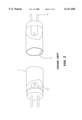
- FIG. 2 illustrates the structure of a piezoelectric porcelain step-up discharge tube according to the present invention
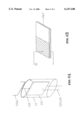
- FIG. 3A illustrates the structure of the piezoelectric member
- FIG. 3B is a perspective view of the piezoelectric porcelain
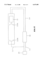
- FIG. 4 is a circuit diagram of the present invention.
- the piezoelectric-type porcelain step-up discharge tube 10 generally comprises a tubular member 11 which is first vacuumed and then filled with a substance which is easily activated to discharge (as mercury vapor and argon filled into conventional fluorescent tube), and a plug 14 at an end of the tubular member 11 for power input.
- An opposite end of the tubular member 11 is provided with a conductive terminal 15 which is electrically connected to the plug 14 through a layer of conductive material 12 coated on the outer surface of the tubular member 11.
- Th e conductive material 12 may be made of transparent material such as vaporized tin halide, conductive printing ink or a conductive wire.
- FIG. 4 illustrates an electrical circuit of the present invention.
- the power source 20 is electrically connected to the control IC 30 via a conductive wire La.
- a conductive wire Lb is connected between an output of the IC and the plug terminal 14 of the discharge tube 10.
- the conductive end 15 of the discharge tube 10 is connected to the power source 20 via a conductive wire Lc thereby providing a closed circuit.
- the porcelain step-up device 13 is made of a piezoelectric material.
- the piezoelectric effect was discovered in the late nineteenth century, which states that compression of a crystal of quartz generates an electrostatic voltage across it, and conversely, application of an electric field may cause the crystal to expand or contract in certain directions.
- piezoelectric effect is the interaction of mechanical and electrical stress-strain variables in a medium.
- the present invention converts strain into voltage so as to achieve the purpose of adjusting voltages.
- IN represents the input end of the porcelain piezoelectric plate 131
- OUT the output end of the porcelain piezoelectric plate 131
- the horizontal arrows the voltage converted from oscillation As shown in FIG. 3B, IN represents the input end of the porcelain piezoelectric plate 131, the vertical arrows the oscillation converted from the voltage, OUT the output end of the porcelain piezoelectric plate 131, and the horizontal arrows the voltage converted from oscillation.
- porcelain piezoelectric transformer is higher than 95% in efficiency.
- the conventional coil transformer only has an efficiency of 70-80%.
- FIG. 3A illustrates the structure of the piezoelectric assembly 13.
- the piezoelectric assembly 13 includes a piezoelectric porcelain plate 131 provided with an input end having two terminals 134 and 135 for connecting with the input plug 14 of the discharge tube 14.
- the other end of the porcelain plate 131 is provided with a discharge electrode 133a so that the voltage applied to the input end will be transmitted to the discharge electrode 133a by piezoelectric effect thereby causing the discharge electrode 133 to emit free electrons and therefore activating the electrons to move at a high speed to discharge.
- the layer of conductive material 12 or conductive wire
- the free electrons will move at a high speed between the electrodes 133a and 133b and the resistance is decreased. In the meantime, a lower voltage can be applied to keep on discharging.
- the present invention does not need a conventional starter and ballast.
- the present invention utilizes piezoelectric material to convert the voltage from the input end into starting and working voltages by piezoelectric effect to activate electrons to discharge and keep on discharging.
- the piezoelectric device [13] is fitted inside a glass tube 13 which the air has been taken out of, heat-treated and high pressure impact treated.
- the advantages of taking air out of the glass tube 135 are as follows: 1. the electrode will not corrode as it is isolated from the atmosphere; 2. good discharging effect; 3. low oscillation resistance; 4. no electromagnetic and discharge interference.
- the discharge electrodes 133a and 133b may be modified to adapt to different types of lamp tubes so as to obtain optimum discharging way.
- the preferred embodiment described herein is only an exemplary illustration of the present invention, but not intended to limit the scope of the present invention.
- the discharge electrodes in this preferred embodiment are a pair of fork-like members 133a and 133b arranged opposite to each other.
- the power source 20 supplies a voltage of direct or alternating current through the conductive wire La to the control IC 30 which is responsible for providing a high voltage for starting and a relatively low voltage for working to an end of the discharge 10 via a conductive wire Lb and the discharge electrode 133b is connected to the power source 20 via a conductive wire Lc to form a closed circuit.
Landscapes
- Amplifiers (AREA)
- Thermistors And Varistors (AREA)
- Vessels And Coating Films For Discharge Lamps (AREA)
Abstract
A piezoelectric porcelain step-up discharge tube includes a vacuum tube having an inner surface coated with fluorescent material and filled with a substance which can be easily activated to discharge, an input plug mounted on one end of the vacuum tube, a conducting terminal arranged on another end of the vacuum tube, a porcelain step-up device arranged within the vacuum tube and having an end electrically connected with the input plug and another end made of piezoelectric material for providing a discharging electrode for supplying a starting and working voltage, and a conductive material coated on an outer side of the vacuum tube and electrically connecting the input plug to the conducting terminal.
Description
1. Field of the Invention
This invention is related to a discharge tube and in particular to one which utilizes piezoelectric material to provide required voltage for the discharge tube.
2. Description of the Prior Art
The conventional fluorescent lamp is a mercury-vapor electric-discharge lamp having the inside of the bulb or tube coated with fluorescent material so that ultraviolet radiation from the discharge is converted to light of an acceptable color. As shown in FIG. 1, the fluorescent lamp includes an elongated tube 1 which is filled with mercury-vapor and a small amount of argon and coated with fluorescent material 2 on the inner surface. Both ends of the elongated tube 1 are each provided with a filament 3 which is coated with calcium oxide or barium oxide for increasing its emission capability. The filament 3 is also used as the electrode. The elongated tube 1 is provided with two plugs 4 at two ends thereof. As the filaments at two ends of the elongated tube 1 are applied with a high voltage, the cathode will emit a large amount of electrons toward the anode and the electrons will collide with the gas atoms thereby ionizing the gas atoms and releasing a large amount of electrons. As the speed of the electrons moving toward the anode exceeds a certain value, discharge will take place, causing the mercury-vapor to emit ultraviolet light which will be converted to visible light by the fluorescent material 2.
In order to ionize the gas to discharge, a high voltage must be applied to both ends of the fluorescent lamp and so a starting device, ballast and a starter are required for supplying current to the filaments so as to emit a large amount of free electrons, producing a momentary high voltage to activate electrons to move at a high speed, and lowering the voltage applied to both ends of the fluorescent lamp and cutting off the current supplying thereto when discharge takes place. For causing the filaments to emit a large amount of electrons, the filaments must be sufficiently heated and so the filaments must be supplied with current by a push-button device or a starting device. A higher voltage is required to speed up electrons and ionize mercury molecules when starting, and the discharge can be maintained by a lower voltage. A ballast is usually used for accomplishing the demands of voltage variations in starting and use.
However, the conventional fluorescent lamp cannot convert all of the electric energy into visible light and a relatively large amount of the electric energy is converted into heat thereby lowering the efficiency to 05.-0.6. In addition, after having used for a certain period of time, the emission substance will be all consumed and both ends of the fluorescent lamp will be blackened thereby ending the service life of the fluorescent lamp.
This invention is related to a piezoelectric porcelain step-up discharge tube.
It is the primary object of the present invention to provide an improved discharge tube which is low in manufacturing cost.
It is another object of the present invention to provide an improved discharge tube which has a relatively long service life.
It is still another object of the present invention to provide an improved discharge tube which can work steadily.
It is still another object the present invention to provide an improved discharge tube which will not generate frequency and noise interference.
It is a further object of the present invention to provide an improved discharge tube which is easy to control in illumination intensity.
The foregoing objects and summary provide only a brief introduction to the present invention. To fully appreciate these and other objects of the present invention as well as the invention itself, all of which will become apparent to those skilled in the art, the following detailed description of the invention and the claims should be read in conjunction with the accompanying drawings. Throughout the specification and drawings identical reference numerals refer to identical or similar parts.
Many other advantages and features of the present invention will become manifest to those versed in the art upon making reference to the detailed description and the accompanying sheets of drawings in which a preferred structural embodiment incorporating the principles of the present invention is shown by way of illustrative example.
FIG. 1 illustrates a prior art fluorescent lamp;
FIG. 2 illustrates the structure of a piezoelectric porcelain step-up discharge tube according to the present invention;
FIG. 3A illustrates the structure of the piezoelectric member;
FIG. 3B is a perspective view of the piezoelectric porcelain; and
FIG. 4 is a circuit diagram of the present invention.
For the purpose of promoting an understanding of the principles of the invention, reference will now be made to the embodiment illustrated in the drawings. Specific language will be used to describe same. It will, nevertheless, be understood that no limitation of the scope of the invention is thereby intended, such alterations and further modifications in the illustrated device, and such further applications of the principles of the invention as illustrated herein being contemplated as would normally occur to one skilled in the art to which the invention relates.
With reference to the drawings and in particular to FIGS. 2, 3 and 4, the piezoelectric-type porcelain step-up discharge tube 10 according to the present invention generally comprises a tubular member 11 which is first vacuumed and then filled with a substance which is easily activated to discharge (as mercury vapor and argon filled into conventional fluorescent tube), and a plug 14 at an end of the tubular member 11 for power input. An opposite end of the tubular member 11 is provided with a conductive terminal 15 which is electrically connected to the plug 14 through a layer of conductive material 12 coated on the outer surface of the tubular member 11. Th e conductive material 12 may be made of transparent material such as vaporized tin halide, conductive printing ink or a conductive wire.
FIG. 4 illustrates an electrical circuit of the present invention. As shown, there is a porcelain step-up device 13 within the discharge tube 10 for meeting demands for different voltages in starting and actual operation. The power source 20 is electrically connected to the control IC 30 via a conductive wire La. A conductive wire Lb is connected between an output of the IC and the plug terminal 14 of the discharge tube 10. The conductive end 15 of the discharge tube 10 is connected to the power source 20 via a conductive wire Lc thereby providing a closed circuit.
The porcelain step-up device 13 is made of a piezoelectric material. The piezoelectric effect was discovered in the late nineteenth century, which states that compression of a crystal of quartz generates an electrostatic voltage across it, and conversely, application of an electric field may cause the crystal to expand or contract in certain directions. In brief, piezoelectric effect is the interaction of mechanical and electrical stress-strain variables in a medium. By means of this effect, the present invention converts strain into voltage so as to achieve the purpose of adjusting voltages. As shown in FIG. 3B, IN represents the input end of the porcelain piezoelectric plate 131, the vertical arrows the oscillation converted from the voltage, OUT the output end of the porcelain piezoelectric plate 131, and the horizontal arrows the voltage converted from oscillation. Hence, when a voltage is applied to the input end IN, there will be a different voltage at the output end OUT. The voltage applied to the output end OUT may be used for determining the resonance point of the resonance frequency. The voltage and frequency at the input end may be controlled by a chip such as required for searching oscillation frequency in voltage 12V to 110V or 220V. The relevant factors of the parameter voltage and current are comparatively easy to control. According to experiments, porcelain piezoelectric transformer is higher than 95% in efficiency. The conventional coil transformer only has an efficiency of 70-80%.
FIG. 3A illustrates the structure of the piezoelectric assembly 13. As shown, the piezoelectric assembly 13 includes a piezoelectric porcelain plate 131 provided with an input end having two terminals 134 and 135 for connecting with the input plug 14 of the discharge tube 14. The other end of the porcelain plate 131 is provided with a discharge electrode 133a so that the voltage applied to the input end will be transmitted to the discharge electrode 133a by piezoelectric effect thereby causing the discharge electrode 133 to emit free electrons and therefore activating the electrons to move at a high speed to discharge. At the beginning of discharge, the layer of conductive material 12 (or conductive wire) will be conducted between the input plug 14 and the conducting terminal 15. When the free electrons are sped up (i.e. after starting), the free electrons will move at a high speed between the electrodes 133a and 133b and the resistance is decreased. In the meantime, a lower voltage can be applied to keep on discharging.
From the above, it is understood that the present invention does not need a conventional starter and ballast. In brief, the present invention utilizes piezoelectric material to convert the voltage from the input end into starting and working voltages by piezoelectric effect to activate electrons to discharge and keep on discharging.
Turning now to FIG. 3A, the piezoelectric device [13] is fitted inside a glass tube 13 which the air has been taken out of, heat-treated and high pressure impact treated. The advantages of taking air out of the glass tube 135 are as follows: 1. the electrode will not corrode as it is isolated from the atmosphere; 2. good discharging effect; 3. low oscillation resistance; 4. no electromagnetic and discharge interference. In addition, the discharge electrodes 133a and 133b may be modified to adapt to different types of lamp tubes so as to obtain optimum discharging way. The preferred embodiment described herein is only an exemplary illustration of the present invention, but not intended to limit the scope of the present invention. The discharge electrodes in this preferred embodiment are a pair of fork-like members 133a and 133b arranged opposite to each other.
Conclusively, the power source 20 supplies a voltage of direct or alternating current through the conductive wire La to the control IC 30 which is responsible for providing a high voltage for starting and a relatively low voltage for working to an end of the discharge 10 via a conductive wire Lb and the discharge electrode 133b is connected to the power source 20 via a conductive wire Lc to form a closed circuit.
It will be understood that each of the elements described above, or two or more together may also find a useful application in other types of methods differing from the type described above.
While certain novel features of this invention have been shown and described and are pointed out in the annexed claim, it is not intended to be limited to the details above, since it will be understood that various omissions, modifications, substitutions and changes in the forms and details of the device illustrated and in its operation can be made by those skilled in the art without departing in any way from the spirit of the present invention.
Without further analysis, the foregoing will so fully reveal the gist of the present invention that others can, by applying current knowledge, readily adapt it for various applications without omitting features that, from the standpoint of prior art, fairly constitute essential characteristics of the generic or specific aspects of this invention.
Claims (6)
1. A piezoelectric porcelain step-up discharge tube comprising:
a vacuum tube having an inner surface coated with fluorescent material and filled with a substance which can be easily activated to discharge;
an input plug mounted on one end of said vacuum tube;
a conducting terminal arranged on another end of said vacuum tube;
a porcelain step-up device arranged within said vacuum tube and having an end electrically connected with said input plug and another end made of piezoelectric material for providing a discharging electrode for supplying a starting and working voltage; and
a conductive material coated on an outer side of said vacuum tube and electrically connecting said input plug to said conducting terminal.
2. The piezoelectric porcelain step-up discharge tube as claimed in claim 1, wherein said porcelain step-up device is enclosed within a vacuum container.
3. The piezoelectric porcelain step-up discharge tube as claimed in claim 1, wherein said porcelain step-up member has two fork-like opposite discharge electrodes.
4. The piezoelectric porcelain step-up discharge tube as claimed in claim 1, wherein said conductive material is transparent.
5. The piezoelectric porcelain step-up discharge tube as claimed in claim 1, wherein said conductive material is made of tin halide.
6. The piezoelectric porcelain step-up discharge tube as claimed in claim 1, wherein said conductive material is made of conductive ink.
Priority Applications (2)
| Application Number | Priority Date | Filing Date | Title |
|---|---|---|---|
| US09/113,970 US6147448A (en) | 1998-07-13 | 1998-07-13 | Piezolelectric porcelain step-up discharge tube |
| DE29814795U DE29814795U1 (en) | 1998-07-13 | 1998-08-18 | Piezoelectric porcelain amplifier discharge tube |
Applications Claiming Priority (2)
| Application Number | Priority Date | Filing Date | Title |
|---|---|---|---|
| US09/113,970 US6147448A (en) | 1998-07-13 | 1998-07-13 | Piezolelectric porcelain step-up discharge tube |
| DE29814795U DE29814795U1 (en) | 1998-07-13 | 1998-08-18 | Piezoelectric porcelain amplifier discharge tube |
Publications (1)
| Publication Number | Publication Date |
|---|---|
| US6147448A true US6147448A (en) | 2000-11-14 |
Family
ID=26061759
Family Applications (1)
| Application Number | Title | Priority Date | Filing Date |
|---|---|---|---|
| US09/113,970 Expired - Fee Related US6147448A (en) | 1998-07-13 | 1998-07-13 | Piezolelectric porcelain step-up discharge tube |
Country Status (2)
| Country | Link |
|---|---|
| US (1) | US6147448A (en) |
| DE (1) | DE29814795U1 (en) |
Cited By (3)
| Publication number | Priority date | Publication date | Assignee | Title |
|---|---|---|---|---|
| US6387115B1 (en) * | 2000-07-27 | 2002-05-14 | Heraeus Noblelight Gmbh | Photodynamic cylindrical lamp with asymmetrically located electrodes and its use |
| DE102007055014A1 (en) * | 2007-11-14 | 2009-05-28 | Forschungsverbund Berlin E.V. | Method and device for igniting and maintaining a plasma |
| US10164165B2 (en) | 2013-11-08 | 2018-12-25 | Epcos Ag | Piezoelectric transformer and counter electrode |
Citations (1)
| Publication number | Priority date | Publication date | Assignee | Title |
|---|---|---|---|---|
| US4404029A (en) * | 1979-11-26 | 1983-09-13 | Tdk Electronics Co., Ltd. | Non-linear polycrystalline barium titanate-type dielectric element |
-
1998
- 1998-07-13 US US09/113,970 patent/US6147448A/en not_active Expired - Fee Related
- 1998-08-18 DE DE29814795U patent/DE29814795U1/en not_active Expired - Lifetime
Patent Citations (1)
| Publication number | Priority date | Publication date | Assignee | Title |
|---|---|---|---|---|
| US4404029A (en) * | 1979-11-26 | 1983-09-13 | Tdk Electronics Co., Ltd. | Non-linear polycrystalline barium titanate-type dielectric element |
Cited By (3)
| Publication number | Priority date | Publication date | Assignee | Title |
|---|---|---|---|---|
| US6387115B1 (en) * | 2000-07-27 | 2002-05-14 | Heraeus Noblelight Gmbh | Photodynamic cylindrical lamp with asymmetrically located electrodes and its use |
| DE102007055014A1 (en) * | 2007-11-14 | 2009-05-28 | Forschungsverbund Berlin E.V. | Method and device for igniting and maintaining a plasma |
| US10164165B2 (en) | 2013-11-08 | 2018-12-25 | Epcos Ag | Piezoelectric transformer and counter electrode |
Also Published As
| Publication number | Publication date |
|---|---|
| DE29814795U1 (en) | 1998-12-03 |
Similar Documents
| Publication | Publication Date | Title |
|---|---|---|
| US4093893A (en) | Short arc fluorescent lamp | |
| US5300860A (en) | Capacitively coupled RF fluorescent lamp with RF magnetic enhancement | |
| US5325024A (en) | Light source including parallel driven low pressure RF fluorescent lamps | |
| US5905344A (en) | Discharge lamps and methods for making discharge lamps | |
| RU2123217C1 (en) | Gas-discharge radiating tube | |
| US4266166A (en) | Compact fluorescent light source having metallized electrodes | |
| EP1498931B1 (en) | Cathodoluminescent light source | |
| US5289085A (en) | Capacitively driven RF light source having notched electrode for improved starting | |
| KR20030057323A (en) | Cold cathode type fluorescent lamp | |
| US5309061A (en) | Compact fluorescent lamp having incandescent lamp starting aid | |
| US5278474A (en) | Discharge tube | |
| US6147448A (en) | Piezolelectric porcelain step-up discharge tube | |
| US5066892A (en) | Glow discharge lamp with incandescent filament | |
| JPH02220345A (en) | Gas discharge tube and indirectly heated cathode and drive circuit therefor | |
| US6710535B2 (en) | Low-pressure gas discharge lamps | |
| EP0378338B1 (en) | Discharge tube | |
| JP3400489B2 (en) | Composite discharge lamp | |
| US3657591A (en) | High intensity far u.v. radiation source | |
| EP2337432B1 (en) | Resonance circuitry for a field emission lighting arrangement | |
| US5041765A (en) | Negative glow discharge lamp device | |
| JP3055594U (en) | Discharge tube and lighting device thereof | |
| US5146135A (en) | Glow discharge lamp having anode probes | |
| JPH04501485A (en) | Glow discharge lamp with thermal switch creating two hot spots on the cathode | |
| CN2343676Y (en) | Piezoelectric ceramic booster discharge tube | |
| KR920000482B1 (en) | Light emitting device |
Legal Events
| Date | Code | Title | Description |
|---|---|---|---|
| FPAY | Fee payment |
Year of fee payment: 4 |
|
| REMI | Maintenance fee reminder mailed | ||
| LAPS | Lapse for failure to pay maintenance fees | ||
| STCH | Information on status: patent discontinuation |
Free format text: PATENT EXPIRED DUE TO NONPAYMENT OF MAINTENANCE FEES UNDER 37 CFR 1.362 |
|
| FP | Lapsed due to failure to pay maintenance fee |
Effective date: 20081114 |