US6147322A - Laser texturing magnetic recording medium with ultra-fine texture pattern - Google Patents
Laser texturing magnetic recording medium with ultra-fine texture pattern Download PDFInfo
- Publication number
- US6147322A US6147322A US09/125,152 US12515298A US6147322A US 6147322 A US6147322 A US 6147322A US 12515298 A US12515298 A US 12515298A US 6147322 A US6147322 A US 6147322A
- Authority
- US
- United States
- Prior art keywords
- laser
- arrangement
- modulator
- randomly
- data storage
- Prior art date
- Legal status (The legal status is an assumption and is not a legal conclusion. Google has not performed a legal analysis and makes no representation as to the accuracy of the status listed.)
- Expired - Fee Related
Links
- 230000005291 magnetic effect Effects 0.000 title description 27
- 238000000034 method Methods 0.000 claims abstract description 29
- 238000013500 data storage Methods 0.000 claims abstract description 16
- 230000000694 effects Effects 0.000 abstract description 4
- 239000000758 substrate Substances 0.000 description 24
- 238000005498 polishing Methods 0.000 description 10
- 239000011521 glass Substances 0.000 description 6
- 239000002241 glass-ceramic Substances 0.000 description 5
- 238000005461 lubrication Methods 0.000 description 3
- 239000000463 material Substances 0.000 description 3
- 230000000284 resting effect Effects 0.000 description 3
- PXHVJJICTQNCMI-UHFFFAOYSA-N Nickel Chemical compound [Ni] PXHVJJICTQNCMI-UHFFFAOYSA-N 0.000 description 2
- 238000001000 micrograph Methods 0.000 description 2
- 238000010791 quenching Methods 0.000 description 2
- 238000012360 testing method Methods 0.000 description 2
- 238000005299 abrasion Methods 0.000 description 1
- 239000000919 ceramic Substances 0.000 description 1
- 238000007796 conventional method Methods 0.000 description 1
- 239000013078 crystal Substances 0.000 description 1
- 125000004122 cyclic group Chemical group 0.000 description 1
- 230000007423 decrease Effects 0.000 description 1
- 230000007547 defect Effects 0.000 description 1
- 230000008021 deposition Effects 0.000 description 1
- 238000010586 diagram Methods 0.000 description 1
- 238000005516 engineering process Methods 0.000 description 1
- 238000007667 floating Methods 0.000 description 1
- 239000000314 lubricant Substances 0.000 description 1
- 238000007521 mechanical polishing technique Methods 0.000 description 1
- 238000005459 micromachining Methods 0.000 description 1
- 239000000203 mixture Substances 0.000 description 1
- 238000012986 modification Methods 0.000 description 1
- 230000004048 modification Effects 0.000 description 1
- 229910052759 nickel Inorganic materials 0.000 description 1
- 238000003825 pressing Methods 0.000 description 1
- 230000001681 protective effect Effects 0.000 description 1
- 239000002002 slurry Substances 0.000 description 1
- 238000001228 spectrum Methods 0.000 description 1
- 239000010409 thin film Substances 0.000 description 1
Images
Classifications
-
- G—PHYSICS
- G11—INFORMATION STORAGE
- G11B—INFORMATION STORAGE BASED ON RELATIVE MOVEMENT BETWEEN RECORD CARRIER AND TRANSDUCER
- G11B5/00—Recording by magnetisation or demagnetisation of a record carrier; Reproducing by magnetic means; Record carriers therefor
- G11B5/84—Processes or apparatus specially adapted for manufacturing record carriers
- G11B5/8408—Processes or apparatus specially adapted for manufacturing record carriers protecting the magnetic layer
-
- B—PERFORMING OPERATIONS; TRANSPORTING
- B23—MACHINE TOOLS; METAL-WORKING NOT OTHERWISE PROVIDED FOR
- B23K—SOLDERING OR UNSOLDERING; WELDING; CLADDING OR PLATING BY SOLDERING OR WELDING; CUTTING BY APPLYING HEAT LOCALLY, e.g. FLAME CUTTING; WORKING BY LASER BEAM
- B23K26/00—Working by laser beam, e.g. welding, cutting or boring
- B23K26/02—Positioning or observing the workpiece, e.g. with respect to the point of impact; Aligning, aiming or focusing the laser beam
- B23K26/06—Shaping the laser beam, e.g. by masks or multi-focusing
- B23K26/064—Shaping the laser beam, e.g. by masks or multi-focusing by means of optical elements, e.g. lenses, mirrors or prisms
- B23K26/0648—Shaping the laser beam, e.g. by masks or multi-focusing by means of optical elements, e.g. lenses, mirrors or prisms comprising lenses
-
- B—PERFORMING OPERATIONS; TRANSPORTING
- B23—MACHINE TOOLS; METAL-WORKING NOT OTHERWISE PROVIDED FOR
- B23K—SOLDERING OR UNSOLDERING; WELDING; CLADDING OR PLATING BY SOLDERING OR WELDING; CUTTING BY APPLYING HEAT LOCALLY, e.g. FLAME CUTTING; WORKING BY LASER BEAM
- B23K26/00—Working by laser beam, e.g. welding, cutting or boring
- B23K26/02—Positioning or observing the workpiece, e.g. with respect to the point of impact; Aligning, aiming or focusing the laser beam
- B23K26/06—Shaping the laser beam, e.g. by masks or multi-focusing
- B23K26/0665—Shaping the laser beam, e.g. by masks or multi-focusing by beam condensation on the workpiece, e.g. for focusing
-
- B—PERFORMING OPERATIONS; TRANSPORTING
- B23—MACHINE TOOLS; METAL-WORKING NOT OTHERWISE PROVIDED FOR
- B23K—SOLDERING OR UNSOLDERING; WELDING; CLADDING OR PLATING BY SOLDERING OR WELDING; CUTTING BY APPLYING HEAT LOCALLY, e.g. FLAME CUTTING; WORKING BY LASER BEAM
- B23K26/00—Working by laser beam, e.g. welding, cutting or boring
- B23K26/08—Devices involving relative movement between laser beam and workpiece
- B23K26/0823—Devices involving rotation of the workpiece
-
- B—PERFORMING OPERATIONS; TRANSPORTING
- B23—MACHINE TOOLS; METAL-WORKING NOT OTHERWISE PROVIDED FOR
- B23K—SOLDERING OR UNSOLDERING; WELDING; CLADDING OR PLATING BY SOLDERING OR WELDING; CUTTING BY APPLYING HEAT LOCALLY, e.g. FLAME CUTTING; WORKING BY LASER BEAM
- B23K26/00—Working by laser beam, e.g. welding, cutting or boring
- B23K26/352—Working by laser beam, e.g. welding, cutting or boring for surface treatment
- B23K26/355—Texturing
-
- G—PHYSICS
- G11—INFORMATION STORAGE
- G11B—INFORMATION STORAGE BASED ON RELATIVE MOVEMENT BETWEEN RECORD CARRIER AND TRANSDUCER
- G11B5/00—Recording by magnetisation or demagnetisation of a record carrier; Reproducing by magnetic means; Record carriers therefor
- G11B5/74—Record carriers characterised by the form, e.g. sheet shaped to wrap around a drum
- G11B5/82—Disk carriers
-
- G—PHYSICS
- G11—INFORMATION STORAGE
- G11B—INFORMATION STORAGE BASED ON RELATIVE MOVEMENT BETWEEN RECORD CARRIER AND TRANSDUCER
- G11B5/00—Recording by magnetisation or demagnetisation of a record carrier; Reproducing by magnetic means; Record carriers therefor
- G11B5/84—Processes or apparatus specially adapted for manufacturing record carriers
- G11B5/8404—Processes or apparatus specially adapted for manufacturing record carriers manufacturing base layers
-
- G—PHYSICS
- G11—INFORMATION STORAGE
- G11B—INFORMATION STORAGE BASED ON RELATIVE MOVEMENT BETWEEN RECORD CARRIER AND TRANSDUCER
- G11B2220/00—Record carriers by type
- G11B2220/20—Disc-shaped record carriers
- G11B2220/25—Disc-shaped record carriers characterised in that the disc is based on a specific recording technology
- G11B2220/2508—Magnetic discs
-
- G—PHYSICS
- G11—INFORMATION STORAGE
- G11B—INFORMATION STORAGE BASED ON RELATIVE MOVEMENT BETWEEN RECORD CARRIER AND TRANSDUCER
- G11B23/00—Record carriers not specific to the method of recording or reproducing; Accessories, e.g. containers, specially adapted for co-operation with the recording or reproducing apparatus ; Intermediate mediums; Apparatus or processes specially adapted for their manufacture
- G11B23/0014—Record carriers not specific to the method of recording or reproducing; Accessories, e.g. containers, specially adapted for co-operation with the recording or reproducing apparatus ; Intermediate mediums; Apparatus or processes specially adapted for their manufacture record carriers not specifically of filamentary or web form
- G11B23/0021—Record carriers not specific to the method of recording or reproducing; Accessories, e.g. containers, specially adapted for co-operation with the recording or reproducing apparatus ; Intermediate mediums; Apparatus or processes specially adapted for their manufacture record carriers not specifically of filamentary or web form discs
- G11B23/0028—Details
Definitions
- the present invention relates generally to laser texturing a magnetic recording medium.
- the present invention is particularly applicable to laser-assisted ultra-fine texturing a pattern on the data storage media surface of a magnetic recording medium.
- Conventional magnetic disk drive designs comprise a commonly denominated Contact Start-Stop (CSS) system commencing when the head begins to slide against the surface of the disk as the disk begins to rotate. Upon reaching a predetermined high rotational speed, the head floats in air at a predetermined distance from the surface of the disk due to dynamic pressure effects caused by air flow generated between the sliding surface of the head and the disk.
- the transducer head is maintained at a controlled distance from the recording surface and is supported on a bearing of air as the disk rotates, such that the head can be freely moved in both the circumferential and radial directions to allow data to be recorded on and retrieved from the surface of the disk at a desired position.
- the rotational speed of the disk decreases and the head again begins to slide against the surface of the disk and eventually stops in contact with and pressing against the disk.
- the transducer head contacts the recording surface whenever the disk is stationary, accelerated from a stop and during deceleration just prior to completely stopping.
- the sliding surface of the head repeats the cyclic operation consisting of stopping, and sliding against the surface of the disk, floating in the air, sliding against the surface of the disk and stopping.
- each transducer head it is considered desirable during reading and recording operations to maintain each transducer head as close to its associated recording surface as possible, i.e., to minimize the flying height of the head.
- a smooth recording surface is preferred, as well as a smooth opposing surface of the associated transducer head, thereby permitting the head and the disk to be positioned in close proximity with an attendant increase in predictability and consistent behavior of the air bearing supporting the head.
- the head surface and the recording surface are too flat, then the precision match of these surfaces gives rise to excessive stiction and friction during the start up and stopping phases, thereby causing wear to the head and recording surfaces eventually leading to what is referred to as a "head crash."
- head crash there are competing goals of reduced head/disk friction and minimum transducer flying height.
- Texturing Conventional practices for addressing these apparent competing objectives involve providing a magnetic disk with a roughened surface to reduce the head/disk friction by techniques generally referred to as "texturing.”
- texturing techniques involve polishing the surface of a disk substrate to provide a texture thereon prior to subsequent deposition of layers, such as an underlayer, a magnetic layer, a protective overcoat, and a lubricant topcoat, wherein the textured surface on the substrate is intended to be substantially replicated in the subsequently deposited layers.
- the escalating requirements for high areal recording density impose increasingly greater requirements on thin film magnetic media in terms of coercivity, stiction, squareness, low medium noise and narrow track recording performance.
- increasingly high density and large-capacity magnetic disks require increasingly smaller flying heights, i.e., the distance by which the head floats above the surface of the disk in the CSS drive.
- the requirement to further reduce the flying height of the head challenges the limitations of conventional technology for controlled texturing to avoid head crash.
- Conventional techniques for providing a disk substrate with a textured surface comprise a mechanical operation, such as polishing.
- conventional practices comprise mechanically polishing the surface to provide a data zone having a substantially smooth surface and a landing zone characterized by topographical features, such as protrusions and depressions. See, for example, Nakamura et al., U.S. Pat. No. 5,202,810.
- Conventional mechanical texturing techniques are attendant with numerous disadvantages. For example, it is extremely difficult to provide a clean textured surface due to debris formed by mechanical abrasions. Moreover, the surface inevitably becomes scratched during mechanical operations, which contributes to poor glide characteristics and higher defects.
- the glide avalanche of such a surface based on this testing is below 0.6 ⁇ (at about 0.55 ⁇ ").
- the flying performance of a Winchester-type slider is primarily affected by the micro-waviness that is close to the low frequency portion of the roughness profile.
- a low frequency profile of the exemplary surface profile of FIG. 1 is depicted in FIG. 2.
- the bumps created by the mechanical texturing vary greatly in size over a range of 200 ⁇ m in the radial direction of the disk.
- the largest bump in FIG. 2 is 50 ⁇ high, and the other bumps have lesser heights.
- the surface profile is thus a relatively random profile, with no specified number of peaks, nor defined heights of the bumps and depths of the valleys.
- the randomness of the low frequency profile created by mechanical polishing leads to an unpredictable glide avalanche and an unpredictable flying head performance. This is so even though the overall average roughness is 7.2 ⁇ , since this parameter represents an average and does not necessarily reflect the extent and number of peaks and valleys on the surface.
- An alternative technique to mechanical texturing for texturing a landing zone comprises the use of a laser light beam focused on an upper surface of a non-magnetic substrate. See, for example, Ranjan et al., U.S. Pat. No. 5,062,021, wherein the disclosed method comprises polishing an NiP plated A1 substrate to a specular finish, and then rotating the disk while directing pulsed laser energy over a limited portion of the radius, to provide a textured landing zone leaving the data zone specular.
- the landing zone comprises a plurality of individual laser spots characterized by a central depression surrounded by a substantially circular raised rim.
- a laser texturing technique is disclosed employing a multiple lens focusing system for improved control of the resulting topographical texture.
- a laser texturing technique is disclosed wherein a pulsed, focused laser light beam is passed through a crystal material to control the spacing between resulting protrusions.
- a method for laser texturing a glass or glass-ceramic substrate employing a laser light beam derived from a CO 2 laser source.
- the textured glass or glass-ceramic substrate surface comprises a plurality of protrusions which extend above the substrate surface, without surrounding valleys extending substantially into the substrate as is characteristic of a laser textured metallic substrate.
- a method for laser texturing a glass or glass-ceramic substrate wherein tie height of the protrusions is controlled by controlling the quench rate during resolidification of the laser formed protrusions.
- One of the disclosed techniques for controlling the quench rate comprises preheating a substrate, as by exposure to a first laser light beam, and then exposing the heated substrate to a focused laser light beam.
- laser texturing techniques have proven advantageous, they have not been hitherto employed to texture an ultra-fine pattern on a media surface to have an ultra-low asperity height while ensuring overall tribological glide performance. In order to ensure the tribological glide performance, uniform wave heights represented by elongated aspirates are needed.
- the present invention provides an arrangement comprising a laser and means for forming a texture pattern on a surface with the laser.
- the means for forming a texture pattern includes a modulator that modulates the laser energy output by the laser, and a random signal generator that controls the modulation of the laser energy output by the modulator.
- the laser micro-machining apparatus of the present invention can create randomly elongated asperities.
- the asperity height can be kept low (e.g., about 50 ⁇ in height) with 200 ⁇ m cycle intervals in the circumferential direction, multiple cycles per 200 ⁇ m in the radial direction, and an average horizontal-to-vertical ratio of 4000:1.
- These exemplary parameters compare very favorably to the scale ratio of about 100:1 by current laser-textured bumps. Since there are no deep valleys on the media surface, there is less air turbulence and easier lubrication at the asperity tips.
- uniform wave-heights provide a more stable air bearing under the flying slider, as well more even contacts between the slider and the media surface when the slider is resting on the surface.
- the asperity height is low, the overall tribological performance is ensured for light-load, low-glide sliders.
- Another aspect of the present invention provides a method of producing an ultra-fine texture pattern on a data storage media surface for ultra-low glide and tribology performance.
- a laser beam is randomly modulated and focused on the data storage media surface to create randomly elongated asperities on the media surface.
- a media surface is created having a uniformity that is represented by regular asperity heights, regular intervals in the radial direction of the media surface (such as a disk), and limited randomness in the circumferential direction.
- the earlier stated needs are also met by another aspect of the present invention that provides a magnetic recording medium having a textured media surface.
- the average horizontal-to-vertical ratio of the bumps created on the textured surface is approximately 4000:1.
- the overall height of the bumps (or asperities) is about 50 ⁇ , and there is a 200 ⁇ m cycle-interval in the circumferential direction and multiple cycles per 200 ⁇ m in the radial direction.
- the surface is characterized by regular asperity heights, regular intervals in the radial direction of the media surface, and limited randomness in the circumferential direction.
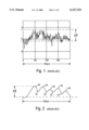
- FIG. 1 is a surface profile of an exemplary magnetic recording medium surface that has been mechanically textured in accordance with the prior art.
- FIG. 2 is a low frequency profile of the surface of the magnetic recording medium having the surface profile of FIG. 1 mechanically textured in accordance with the prior art.
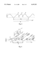
- FIG. 3 is a low frequency profile of an exemplary magnetic recording medium surface that has been textured in accordance with an embodiment of the present invention.
- FIG. 4 is a three-dimensional representation of the magnetic recording medium surface of FIG. 3.
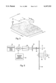
- FIG. 5 is a three dimensional microphotograph of an elongated asperity produced in accordance with an embodiment of the present invention.
- FIG. 6 is a schematic diagram of an arrangement in accordance with an embodiment of the present invention for laser texturing magnetic recording media to produce an ultra-low glide avalanche media surface.
- the present invention addresses and solves the problem of controlling the texture of a magnetic recording medium surface in such a way as to provide an ultra-low glide avalanche (e.g. less than 0.6 ⁇ "), but in a controllable and repeatable manner.
- an ultra-low glide avalanche e.g. less than 0.6 ⁇
- FIG. 1 depicts a two-dimensional representation of the prior art mechanically-textured ultra-fine surface profile of a magnetic recording medium such as a disk.
- the mechanical polishing of the substrate, leading to the surface profile of FIG. 1 displays many peaks and valleys having very high peaks and very low valleys.
- the pattern is not controlled due to the use of a slurry during the mechanical polishing procedure.
- a low frequency profile of the surface spectrum is provided in FIG. 2. This reveals, for example, five peaks 10 and five valleys 12 of varying heights and depths within a 200 ⁇ m range in the radial direction.
- the highest peak 10 within this 200 ⁇ m range is 50 ⁇ .
- a media surface with an average roughness Ra of 7.2 ⁇ and a glide avalanche of 0.55 ⁇ m may be achieved.
- the air bearing under a flying slider will be less stable as the asperity heights of the peaks 10 vary in a random manner.
- Another concern is caused by the varying depths of the valleys 12, which raises concerns regarding the lubrication of the peaks 10 of the asperities.
- the deep valleys 12 create more air turbulence for the slider.
- FIG. 3 depicts a two dimensional representation of the cross-section of a magnetic recording medium surface profile that has been laser textured in accordance with the present invention.
- the peaks 14 have a height of approximately 50 ⁇ . Over a 200 ⁇ m range, in the radial direction, a specified number of peaks and valleys are provided. In the exemplary embodiment of FIG. 3, in a 200 ⁇ m cycle (or range), there are three peaks 14 and two valleys 16. Notably, in this embodiment, the peaks 14 of are a substantially uniform height of 50 ⁇ .
- the uniform wave heights or asperity heights of the peaks 14 provide a very stable air bearing under a flying slider, as well as more even contacts between the slider and the surface when the slider is resting on the surface.
- the laser texturing of the surface of the magnetic recording media provides an ultra-low glide avalanche. For example, in the embodiment of FIG. 3, the media surface has a glide avalanche below 0.6 ⁇ m or 150 ⁇ . Prior laser texturing of surfaces were limited to about 200 ⁇ for the glide avalanche.
- an average horizontal-to-vertical ratio of 4,000:01 is achieved. This very favorably compares to the average horizontal-to-vertical ratio of approximately 100:01 achieved by current laser-textured asperities.
- FIG. 4 is a three-dimensional representation of the media surface laser-textured in accordance with the embodiments of the present invention. This surface has also been textured to reach a glide avalanche of approximately 0.55 ⁇ m.
- a cycle 18 of 200 ⁇ m. Within each cycle 18, there are three asperities having peaks 14 and valleys 16. These cycles 18 are repeated in the radial direction R.
- the cycle-interval in the circumferential direction (arrow C) is also 200 ⁇ m in the exemplary embodiment depicted in FIG. 4.
- the cycle-interval in the circumferential direction C is denoted with reference numeral 20 in FIG. 4. Unlike the cycle-intervals 18 in the radial direction R, which are regular intervals, the cycle-intervals 20 in the circumferential direction C are more randomly distributed.
- the reason that limited randomness in a circumferential direction is advantageous is that it eliminates resonance during operation.
- the randomness of the asperities in the circumferential direction C prevents resonant vibrations from affecting the slider or flying head.
- Resonance is not as critical a concern in the radial direction of the disk. This is because the head does not travel nearly as fast in the radial direction with respect to the surface of the disk as the disk rotates in a circumferential direction underneath the head.
- the cycle-intervals 18 in a radial direction R in the media surface may be made to be regular intervals.
- FIG. 5 is a microphotograph of an exemplary laser textured asperity 22 that is in the circumferential direction C.
- the single elongated asperity 22 has a height of approximately 50 ⁇ , and has a length L and a width W that is adjustable by suitable configuration of the wafer texturing arrangement.
- FIG. 6 is an exemplary embodiment of a laser-optic system configured to laser-texture a surface to provide an ultra-low glide avalanche media surface.
- the laser optics system 30 includes a continuous-wave laser 32 that produces a laser output. This output is then modulated by a modulator 34.
- the modulator 34 is an acoustic-optical modulator that operates to modulate the laser-beam output from the laser 32. The modulation may be performed in many different manners, but in preferred embodiments of the present invention, the modulation is performed randomly.
- a random signal generator 36 controls the modulation of the laser-beam through controlling the modulator 34.
- the random signal generator 36 produces a control signal at random points in time to cause the modulator 34 to pulse the laser beam produced by the continuous-wave laser 32 in a random manner.
- the randomly pulsed laser beam modulated by the modulator 34 is received by a beam expander 38 that expands and collimates the laser beam.
- the expanded, collimated laser beam is passed through an aperture 40 and focused through a focusing lens 42 onto the surface to be textured.
- the recording media to be surfaced is a magnetic recording media such as a magnetic recording disk 44.
- the disc 44 is mounted to a spindle 46 that is moved in two different manners.
- the spindle 46 is rotated as indicated by arrow B in FIG. 6.
- the spindle 46 is moved to translate the surface of the disk 44 in a vertical direction in FIG. 6, as indicated by arrow A.
- the movement of the spindle 46 and the disk 44 in the directions of arrow A may be done in a timed manner in order to provide the regular intervals in a radial direction.
- the randomness in the circimferential direction C is created by the pulsing of the laser beam through the use of the random signal generator 36 and the modulator 34.
- the laser beam energy being applied to the surface of the disk 44 as it is rotated in the direction of arrow B is applied in a randomly pulsed manner.
- the asperities will be randomly located along a single circular track on a surface of the disk 44. As stated earlier, this limited randomness avoids resonances from being created that will cause vibrations in the slider or in the flying head during operation of the disk drive.
- the wavelength of the laser beam produced by the continuous wave laser 32 should be selected to produce the randomly elongated asperities on the surface to be textured due to a thermal expansion effect.
- a 1064 nm wavelength laser is appropriate.
- a 10 mm wavelength laser is appropriate to use as the continuous-wave laser 32. If used on other types of materials, one of ordinary skill in the art would select the appropriate wavelength laser 32 to texture the substrate in accordance with the present invention.
- the present invention provides a method and apparatus for creating an ultra-low glide avalanche media surface that has a controllable, repeatable texture pattern.
Abstract
Description
Claims (19)
Priority Applications (1)
| Application Number | Priority Date | Filing Date | Title |
|---|---|---|---|
| US09/125,152 US6147322A (en) | 1997-09-02 | 1998-08-10 | Laser texturing magnetic recording medium with ultra-fine texture pattern |
Applications Claiming Priority (3)
| Application Number | Priority Date | Filing Date | Title |
|---|---|---|---|
| US5732397P | 1997-09-02 | 1997-09-02 | |
| US09/125,152 US6147322A (en) | 1997-09-02 | 1998-08-10 | Laser texturing magnetic recording medium with ultra-fine texture pattern |
| PCT/US1998/016655 WO1999011418A1 (en) | 1997-09-02 | 1998-08-10 | Laser texturing recording medium with a random signal driven modulator |
Publications (1)
| Publication Number | Publication Date |
|---|---|
| US6147322A true US6147322A (en) | 2000-11-14 |
Family
ID=22009893
Family Applications (1)
| Application Number | Title | Priority Date | Filing Date |
|---|---|---|---|
| US09/125,152 Expired - Fee Related US6147322A (en) | 1997-09-02 | 1998-08-10 | Laser texturing magnetic recording medium with ultra-fine texture pattern |
Country Status (8)
| Country | Link |
|---|---|
| US (1) | US6147322A (en) |
| JP (1) | JP2001514430A (en) |
| KR (1) | KR100584645B1 (en) |
| CN (1) | CN1125441C (en) |
| DE (1) | DE19882653T1 (en) |
| GB (1) | GB2344551B (en) |
| HK (1) | HK1028579A1 (en) |
| WO (1) | WO1999011418A1 (en) |
Cited By (6)
| Publication number | Priority date | Publication date | Assignee | Title |
|---|---|---|---|---|
| US20060189091A1 (en) * | 2004-11-11 | 2006-08-24 | Bo Gu | Method and system for laser hard marking |
| US20060188756A1 (en) * | 2001-03-27 | 2006-08-24 | Nippon Sheet Glass Co., Ltd. | Substrate for information recording media and manufacturing method thereof, information recording medium, and starting material glass plate |
| US20070297060A1 (en) * | 2006-06-22 | 2007-12-27 | Bastawros Adel F | Mastering tools and systems and methods for forming a plurality of cells on the mastering tools |
| US20070297480A1 (en) * | 2006-06-22 | 2007-12-27 | Bastawros Adel F | Mastering tools and systems and methods for forming a cell on the mastering tools |
| US20120061359A1 (en) * | 2010-09-10 | 2012-03-15 | Silvo Heinritz | Method for producing coarse surface structures |
| US20140217058A1 (en) * | 2011-09-23 | 2014-08-07 | Boegli-Gravures S.A. | Method and device for producing a structured surface on a steel embossing roller |
Families Citing this family (5)
| Publication number | Priority date | Publication date | Assignee | Title |
|---|---|---|---|---|
| CN100462180C (en) * | 2005-10-28 | 2009-02-18 | 中国科学院力学研究所 | Laser processing system and method for roller surface burr without regular deflection burr |
| CN100475412C (en) * | 2005-11-01 | 2009-04-08 | 中国科学院力学研究所 | Coarsening laser processing system and method for surface of roller with circumferential irregular coarsening dots |
| JP5830890B2 (en) * | 2011-03-24 | 2015-12-09 | 富士電機株式会社 | Magnetic disk device, magnetic disk and manufacturing method thereof |
| CN102699524B (en) * | 2012-05-25 | 2016-03-02 | 武汉华工激光工程有限责任公司 | A kind of processing method of multiple head laser disordered texturing roller surface and process equipment |
| JP6843347B2 (en) * | 2016-08-09 | 2021-03-17 | 学校法人 名古屋電気学園 | Surface microstructure formation method, structure manufacturing method |
Citations (5)
| Publication number | Priority date | Publication date | Assignee | Title |
|---|---|---|---|---|
| US5279775A (en) * | 1992-06-10 | 1994-01-18 | Iomega Corporation | Acousto-optical intensity control of laser beam during etching of optical servo information of magnetic media |
| US5283773A (en) * | 1992-06-10 | 1994-02-01 | Iomega Corporation | Steering laser beam while etching optical servo tracks for magnetic disks |
| US5416298A (en) * | 1990-11-23 | 1995-05-16 | Zed Instruments Limited | Laser engraving apparatus |
| US5760880A (en) * | 1995-05-01 | 1998-06-02 | E. I. Du Pont De Nemours And Company | Laser apparatus |
| US5910262A (en) * | 1997-02-06 | 1999-06-08 | International Business Machines Corporation | Method and tool for laser texturing of glass substrates |
Family Cites Families (3)
| Publication number | Priority date | Publication date | Assignee | Title |
|---|---|---|---|---|
| US5528922A (en) * | 1994-12-27 | 1996-06-25 | International Business Machines Corporation | Method of making disk bumps with laser pulses for calibrating PZT sliders |
| JPH08249637A (en) * | 1995-03-07 | 1996-09-27 | Hitachi Ltd | Magnetic disk, manufacture thereof and magnetic disk device |
| US6086977A (en) * | 1995-06-21 | 2000-07-11 | Ngk Insulators, Ltd. | Substrates for magnetic discs, magnetic discs and process for producing magnetic discs |
-
1998
- 1998-08-10 JP JP2000508503A patent/JP2001514430A/en active Pending
- 1998-08-10 KR KR1020007002228A patent/KR100584645B1/en not_active IP Right Cessation
- 1998-08-10 CN CN98810844A patent/CN1125441C/en not_active Expired - Fee Related
- 1998-08-10 GB GB0004967A patent/GB2344551B/en not_active Expired - Fee Related
- 1998-08-10 DE DE19882653T patent/DE19882653T1/en not_active Withdrawn
- 1998-08-10 US US09/125,152 patent/US6147322A/en not_active Expired - Fee Related
- 1998-08-10 WO PCT/US1998/016655 patent/WO1999011418A1/en active IP Right Grant
-
2000
- 2000-12-14 HK HK00108030A patent/HK1028579A1/en not_active IP Right Cessation
Patent Citations (5)
| Publication number | Priority date | Publication date | Assignee | Title |
|---|---|---|---|---|
| US5416298A (en) * | 1990-11-23 | 1995-05-16 | Zed Instruments Limited | Laser engraving apparatus |
| US5279775A (en) * | 1992-06-10 | 1994-01-18 | Iomega Corporation | Acousto-optical intensity control of laser beam during etching of optical servo information of magnetic media |
| US5283773A (en) * | 1992-06-10 | 1994-02-01 | Iomega Corporation | Steering laser beam while etching optical servo tracks for magnetic disks |
| US5760880A (en) * | 1995-05-01 | 1998-06-02 | E. I. Du Pont De Nemours And Company | Laser apparatus |
| US5910262A (en) * | 1997-02-06 | 1999-06-08 | International Business Machines Corporation | Method and tool for laser texturing of glass substrates |
Cited By (16)
| Publication number | Priority date | Publication date | Assignee | Title |
|---|---|---|---|---|
| US7604882B2 (en) * | 2001-03-27 | 2009-10-20 | Nippon Sheet Glass Co., Ltd. | Substrate for information recording media and manufacturing method thereof, information recording medium, and starting material glass plate |
| US20060188756A1 (en) * | 2001-03-27 | 2006-08-24 | Nippon Sheet Glass Co., Ltd. | Substrate for information recording media and manufacturing method thereof, information recording medium, and starting material glass plate |
| US20060199045A1 (en) * | 2001-03-27 | 2006-09-07 | Nippon Sheet Glass Co., Ltd. | Substrate for information recording media and manufacturing method thereof, information recording medium, and starting material glass plate |
| US7736770B2 (en) | 2001-03-27 | 2010-06-15 | Nippon Sheet Glass Co., Ltd. | Substrate for information recording media and manufacturing method thereof, information recording medium, and starting material glass plate |
| US20060189091A1 (en) * | 2004-11-11 | 2006-08-24 | Bo Gu | Method and system for laser hard marking |
| US20110011837A1 (en) * | 2006-06-22 | 2011-01-20 | Sabic Innovative Plastics Ip B.V. | Systems for forming a plurality of cells on the mastering tools |
| US20070297480A1 (en) * | 2006-06-22 | 2007-12-27 | Bastawros Adel F | Mastering tools and systems and methods for forming a cell on the mastering tools |
| US7807938B2 (en) * | 2006-06-22 | 2010-10-05 | Sabic Innovative Plastics Ip B.V. | Mastering tools and systems and methods for forming a plurality of cells on the mastering tools |
| US20070297060A1 (en) * | 2006-06-22 | 2007-12-27 | Bastawros Adel F | Mastering tools and systems and methods for forming a plurality of cells on the mastering tools |
| US8222562B2 (en) | 2006-06-22 | 2012-07-17 | Sabic Innovative Plastics Ip B.V. | Systems for forming a plurality of cells on the mastering tools |
| US8262381B2 (en) | 2006-06-22 | 2012-09-11 | Sabic Innovative Plastics Ip B.V. | Mastering tools and systems and methods for forming a cell on the mastering tools |
| CN101484268B (en) * | 2006-06-22 | 2013-04-24 | 沙伯基础创新塑料知识产权有限公司 | Mastering tools, systems and methods for forming a plurality of cells on the mastering tools |
| US20120061359A1 (en) * | 2010-09-10 | 2012-03-15 | Silvo Heinritz | Method for producing coarse surface structures |
| US8507829B2 (en) * | 2010-09-10 | 2013-08-13 | Acsys Lasertechnik Gmbh | Method for producing coarse surface structures |
| US20140217058A1 (en) * | 2011-09-23 | 2014-08-07 | Boegli-Gravures S.A. | Method and device for producing a structured surface on a steel embossing roller |
| US10183318B2 (en) * | 2011-09-23 | 2019-01-22 | Boegli-Gravures S.A. | Method and device for producing a structured surface on a steel embossing roller |
Also Published As
| Publication number | Publication date |
|---|---|
| CN1125441C (en) | 2003-10-22 |
| GB2344551B (en) | 2001-04-04 |
| CN1278198A (en) | 2000-12-27 |
| WO1999011418A1 (en) | 1999-03-11 |
| KR20010023580A (en) | 2001-03-26 |
| KR100584645B1 (en) | 2006-05-30 |
| GB0004967D0 (en) | 2000-04-19 |
| HK1028579A1 (en) | 2001-02-23 |
| GB2344551A (en) | 2000-06-14 |
| DE19882653T1 (en) | 2000-08-10 |
| JP2001514430A (en) | 2001-09-11 |
Similar Documents
| Publication | Publication Date | Title |
|---|---|---|
| US5981902A (en) | Texturing apparatus for magnetic recording medium and magnetic recording medium process thereby | |
| US6147322A (en) | Laser texturing magnetic recording medium with ultra-fine texture pattern | |
| US6297910B1 (en) | Laser-texturing data zone on a magnetic disk surface by using degenerative two wave mixing | |
| US5861196A (en) | Laser texturing a glass or glass-ceramic substrate | |
| US5952058A (en) | Laser texturing magnetic recording medium using fiber optics | |
| US6020045A (en) | Textured magnetic recording medium having a transition zone | |
| US6299429B1 (en) | Dual fiber optic laser texturing | |
| US5955154A (en) | Magnetic recording medium with laser textured glass or glass-ceramic substrate | |
| US5834731A (en) | Laser texturing apparatus with bernoulli holder | |
| US5965215A (en) | Method for laser texturing a landing zone and a data zone of a magnetic recording medium | |
| JP3199266B2 (en) | Laser surface treatment of magnetic recording media | |
| US6207926B1 (en) | Fiber optic laser texturing with optical probe feedback control | |
| JP3030246B2 (en) | Texture device and texture processing method | |
| JP2826087B2 (en) | Texture device and texture processing method | |
| JP2843539B2 (en) | Texture device and texture processing method | |
| US20010008715A1 (en) | Continuous texture features for a disk substrate | |
| US5968608A (en) | Laser texturing of magnetic recording medium using multiple lens focusing | |
| US6180916B1 (en) | Method of manufacturing a magnetic recording medium with a laser textured data zone | |
| US5945197A (en) | Laser texturing of magnetic recording medium using multiple lens focusing | |
| US6068728A (en) | Laser texturing with reverse lens focusing system | |
| JPH0877554A (en) | Magnetic recording medium and substrate | |
| US6320728B1 (en) | Laser textured magnetic surface micro-ridges/grooves to enhance magnetic recording performance | |
| US6093472A (en) | Magnetic recording medium with laser textured glass or glass-ceramic substrate | |
| JPH09295178A (en) | Laser texture device | |
| JPH10244382A (en) | Texture device and its method |
Legal Events
| Date | Code | Title | Description |
|---|---|---|---|
| AS | Assignment |
Owner name: SEAGATE TECHNOLOGY, INC., CALIFORNIA Free format text: ASSIGNMENT OF ASSIGNORS INTEREST;ASSIGNORS:XUAN, JIALUO J.;SHIH, CHUNG-YUANG;REEL/FRAME:010143/0576;SIGNING DATES FROM 19980624 TO 19980625 |
|
| AS | Assignment |
Owner name: SEAGATE TECHNOLOGY LLC, CALIFORNIA Free format text: ASSIGNMENT OF ASSIGNORS INTEREST;ASSIGNOR:SEAGATE TECHNOLOGY, INC.;REEL/FRAME:010983/0351 Effective date: 20000628 |
|
| AS | Assignment |
Owner name: JPMORGAN CHASE BANK, AS COLLATERAL AGENT, NEW YORK Free format text: SECURITY AGREEMENT;ASSIGNOR:SEAGATE TECHNOLOGY LLC;REEL/FRAME:013177/0001 Effective date: 20020513 Owner name: JPMORGAN CHASE BANK, AS COLLATERAL AGENT,NEW YORK Free format text: SECURITY AGREEMENT;ASSIGNOR:SEAGATE TECHNOLOGY LLC;REEL/FRAME:013177/0001 Effective date: 20020513 |
|
| FEPP | Fee payment procedure |
Free format text: PAYOR NUMBER ASSIGNED (ORIGINAL EVENT CODE: ASPN); ENTITY STATUS OF PATENT OWNER: LARGE ENTITY |
|
| FPAY | Fee payment |
Year of fee payment: 4 |
|
| AS | Assignment |
Owner name: SEAGATE TECHNOLOGY LLC, CALIFORNIA Free format text: RELEASE OF SECURITY INTERESTS IN PATENT RIGHTS;ASSIGNOR:JPMORGAN CHASE BANK, N.A., AS ADMINISTRATIVE AGENT (FORMERLY KNOWN AS THE CHASE MANHATTAN BANK);REEL/FRAME:016945/0763 Effective date: 20051130 |
|
| FPAY | Fee payment |
Year of fee payment: 8 |
|
| AS | Assignment |
Owner name: JPMORGAN CHASE BANK, N.A., AS ADMINISTRATIVE AGENT Free format text: SECURITY AGREEMENT;ASSIGNORS:MAXTOR CORPORATION;SEAGATE TECHNOLOGY LLC;SEAGATE TECHNOLOGY INTERNATIONAL;REEL/FRAME:022757/0017 Effective date: 20090507 Owner name: WELLS FARGO BANK, NATIONAL ASSOCIATION, AS COLLATE Free format text: SECURITY AGREEMENT;ASSIGNORS:MAXTOR CORPORATION;SEAGATE TECHNOLOGY LLC;SEAGATE TECHNOLOGY INTERNATIONAL;REEL/FRAME:022757/0017 Effective date: 20090507 |
|
| AS | Assignment |
Owner name: SEAGATE TECHNOLOGY LLC, CALIFORNIA Free format text: RELEASE;ASSIGNOR:JPMORGAN CHASE BANK, N.A., AS ADMINISTRATIVE AGENT;REEL/FRAME:025662/0001 Effective date: 20110114 Owner name: MAXTOR CORPORATION, CALIFORNIA Free format text: RELEASE;ASSIGNOR:JPMORGAN CHASE BANK, N.A., AS ADMINISTRATIVE AGENT;REEL/FRAME:025662/0001 Effective date: 20110114 Owner name: SEAGATE TECHNOLOGY INTERNATIONAL, CALIFORNIA Free format text: RELEASE;ASSIGNOR:JPMORGAN CHASE BANK, N.A., AS ADMINISTRATIVE AGENT;REEL/FRAME:025662/0001 Effective date: 20110114 Owner name: SEAGATE TECHNOLOGY HDD HOLDINGS, CALIFORNIA Free format text: RELEASE;ASSIGNOR:JPMORGAN CHASE BANK, N.A., AS ADMINISTRATIVE AGENT;REEL/FRAME:025662/0001 Effective date: 20110114 |
|
| AS | Assignment |
Owner name: THE BANK OF NOVA SCOTIA, AS ADMINISTRATIVE AGENT, Free format text: SECURITY AGREEMENT;ASSIGNOR:SEAGATE TECHNOLOGY LLC;REEL/FRAME:026010/0350 Effective date: 20110118 |
|
| REMI | Maintenance fee reminder mailed | ||
| LAPS | Lapse for failure to pay maintenance fees | ||
| STCH | Information on status: patent discontinuation |
Free format text: PATENT EXPIRED DUE TO NONPAYMENT OF MAINTENANCE FEES UNDER 37 CFR 1.362 |
|
| FP | Lapsed due to failure to pay maintenance fee |
Effective date: 20121114 |
|
| AS | Assignment |
Owner name: SEAGATE TECHNOLOGY US HOLDINGS, INC., CALIFORNIA Free format text: TERMINATION AND RELEASE OF SECURITY INTEREST IN PATENT RIGHTS;ASSIGNOR:WELLS FARGO BANK, NATIONAL ASSOCIATION, AS COLLATERAL AGENT AND SECOND PRIORITY REPRESENTATIVE;REEL/FRAME:030833/0001 Effective date: 20130312 Owner name: SEAGATE TECHNOLOGY INTERNATIONAL, CAYMAN ISLANDS Free format text: TERMINATION AND RELEASE OF SECURITY INTEREST IN PATENT RIGHTS;ASSIGNOR:WELLS FARGO BANK, NATIONAL ASSOCIATION, AS COLLATERAL AGENT AND SECOND PRIORITY REPRESENTATIVE;REEL/FRAME:030833/0001 Effective date: 20130312 Owner name: SEAGATE TECHNOLOGY LLC, CALIFORNIA Free format text: TERMINATION AND RELEASE OF SECURITY INTEREST IN PATENT RIGHTS;ASSIGNOR:WELLS FARGO BANK, NATIONAL ASSOCIATION, AS COLLATERAL AGENT AND SECOND PRIORITY REPRESENTATIVE;REEL/FRAME:030833/0001 Effective date: 20130312 Owner name: EVAULT INC. (F/K/A I365 INC.), CALIFORNIA Free format text: TERMINATION AND RELEASE OF SECURITY INTEREST IN PATENT RIGHTS;ASSIGNOR:WELLS FARGO BANK, NATIONAL ASSOCIATION, AS COLLATERAL AGENT AND SECOND PRIORITY REPRESENTATIVE;REEL/FRAME:030833/0001 Effective date: 20130312 |