US6134979A - Anti-saw-through spring guide and spring retainer - Google Patents
Anti-saw-through spring guide and spring retainer Download PDFInfo
- Publication number
- US6134979A US6134979A US09/335,326 US33532699A US6134979A US 6134979 A US6134979 A US 6134979A US 33532699 A US33532699 A US 33532699A US 6134979 A US6134979 A US 6134979A
- Authority
- US
- United States
- Prior art keywords
- spring
- switch mechanism
- retainer
- guides
- rolled steel
- Prior art date
- Legal status (The legal status is an assumption and is not a legal conclusion. Google has not performed a legal analysis and makes no representation as to the accuracy of the status listed.)
- Expired - Lifetime
Links
- 230000007246 mechanism Effects 0.000 claims abstract description 32
- 239000010960 cold rolled steel Substances 0.000 claims description 13
- 239000002184 metal Substances 0.000 description 3
- 230000009471 action Effects 0.000 description 1
- 230000008901 benefit Effects 0.000 description 1
- 230000003993 interaction Effects 0.000 description 1
- 238000000034 method Methods 0.000 description 1
- 238000012986 modification Methods 0.000 description 1
- 230000004048 modification Effects 0.000 description 1
Images


Classifications
-
- H—ELECTRICITY
- H01—ELECTRIC ELEMENTS
- H01H—ELECTRIC SWITCHES; RELAYS; SELECTORS; EMERGENCY PROTECTIVE DEVICES
- H01H3/00—Mechanisms for operating contacts
- H01H3/22—Power arrangements internal to the switch for operating the driving mechanism
- H01H3/30—Power arrangements internal to the switch for operating the driving mechanism using spring motor
-
- Y—GENERAL TAGGING OF NEW TECHNOLOGICAL DEVELOPMENTS; GENERAL TAGGING OF CROSS-SECTIONAL TECHNOLOGIES SPANNING OVER SEVERAL SECTIONS OF THE IPC; TECHNICAL SUBJECTS COVERED BY FORMER USPC CROSS-REFERENCE ART COLLECTIONS [XRACs] AND DIGESTS
- Y10—TECHNICAL SUBJECTS COVERED BY FORMER USPC
- Y10T—TECHNICAL SUBJECTS COVERED BY FORMER US CLASSIFICATION
- Y10T74/00—Machine element or mechanism
- Y10T74/18—Mechanical movements
- Y10T74/18856—Oscillating to oscillating
- Y10T74/18864—Snap action
Definitions
- the present invention relates to switches or toggle mechanisms and, in particular, to an improved spring guide and spring retainer.
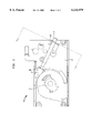
- FIG. 1 a typical switch mechanism 10 is depicted with a rotor cam 12, spring guides 14, spring cam 16, retainer 18 and mechanism housing 20.
- a switch mechanism comprising a mechanism housing, a rotor cam, a spring cam, a spring retainer having a retaining aperture comprising a first curved shape having a convex surface, and spring guides for passing through the retaining aperture in the spring retainer, the spring guides having a second curved shape.
- the spring guides and/or the spring retainer is formed from cold rolled steel.
- FIG. 1 is a schematic side view of a typical prior art switch mechanism
- FIG. 2 is an enlarged sectional view taken along line c--c and showing the detail of the interaction between the spring guides and retainer of the switch mechanism show in FIG. 1;
- FIG. 3A is a sectional view of the switch mechanism shown in FIG. 1 but with the spring guides and spring retainer of the present invention.
- FIG. 3B is an enlarged view of the present invention showing the spring guides in the retaining aperture of the spring retainer.
- FIG. 3A shows a sectional view of the switch mechanism shown in FIG. 1 but with the spring guides and spring retainer of the present invention
- FIG. 3B which is an enlarged view showing greater detail of the novel spring guides 30 of the present invention within the novel shaped retaining aperture 32 in a spring retainer 34.
- Spring guides 30 have a cross-sectional area of an arc of a circle and are stamped from metal to minimize costs of production.
- Retaining aperture 32 is similarly stamped from metal and has a shape of an oval to facilitate contact with a convex surface 30a of each spring guide 30.
- a curved shape to the stamped metal spring guides and a corresponding curved shape to the retaining aperture 32 in spring retainer 34 By providing, in accordance with the present invention, a curved shape to the stamped metal spring guides and a corresponding curved shape to the retaining aperture 32 in spring retainer 34, and depending upon the particular chosen curvature of the spring guides, either a much higher surface area of contact 36 between the convex surface of the spring guide and the edges of the retaining aperture is soon obtained as the spring guides gradually wear as the switch repeatedly functions, or the curvature of the spring guides is so chosen so that the initial contact area between the spring guides and the retaining aperture is larger than the prior art. Because of this greater surface area of contact, the surface pressure between the spring guides and the spring retainer is lower, and thus the potential for "saw-through" is reduced.
- the shape of the spring guides and the aperture in the spring retainer is such that as wear occurs, the resulting area of contact will be larger than the prior art designs, and will increase as further wear increases, resulting in a decrease in the
- the spring guides and/or the spring retainer is stamped from cold rolled steel.
Landscapes
- Driving Mechanisms And Operating Circuits Of Arc-Extinguishing High-Tension Switches (AREA)
- Mechanisms For Operating Contacts (AREA)
- Springs (AREA)
Abstract
Description
Claims (18)
Priority Applications (3)
| Application Number | Priority Date | Filing Date | Title |
|---|---|---|---|
| US09/335,326 US6134979A (en) | 1999-06-17 | 1999-06-17 | Anti-saw-through spring guide and spring retainer |
| CA002311856A CA2311856A1 (en) | 1999-06-17 | 2000-06-15 | Anti-saw-through spring guide and spring retainer |
| MXPA00005888A MXPA00005888A (en) | 1999-06-17 | 2000-06-15 | Anti-saw-through spring guide and spring retainer. |
Applications Claiming Priority (1)
| Application Number | Priority Date | Filing Date | Title |
|---|---|---|---|
| US09/335,326 US6134979A (en) | 1999-06-17 | 1999-06-17 | Anti-saw-through spring guide and spring retainer |
Publications (1)
| Publication Number | Publication Date |
|---|---|
| US6134979A true US6134979A (en) | 2000-10-24 |
Family
ID=23311303
Family Applications (1)
| Application Number | Title | Priority Date | Filing Date |
|---|---|---|---|
| US09/335,326 Expired - Lifetime US6134979A (en) | 1999-06-17 | 1999-06-17 | Anti-saw-through spring guide and spring retainer |
Country Status (3)
| Country | Link |
|---|---|
| US (1) | US6134979A (en) |
| CA (1) | CA2311856A1 (en) |
| MX (1) | MXPA00005888A (en) |
Citations (1)
| Publication number | Priority date | Publication date | Assignee | Title |
|---|---|---|---|---|
| US5944172A (en) * | 1997-10-06 | 1999-08-31 | Allen-Bradley Company, Llc | Biasing assembly for a switching device |
-
1999
- 1999-06-17 US US09/335,326 patent/US6134979A/en not_active Expired - Lifetime
-
2000
- 2000-06-15 MX MXPA00005888A patent/MXPA00005888A/en unknown
- 2000-06-15 CA CA002311856A patent/CA2311856A1/en not_active Abandoned
Patent Citations (1)
| Publication number | Priority date | Publication date | Assignee | Title |
|---|---|---|---|---|
| US5944172A (en) * | 1997-10-06 | 1999-08-31 | Allen-Bradley Company, Llc | Biasing assembly for a switching device |
Also Published As
| Publication number | Publication date |
|---|---|
| CA2311856A1 (en) | 2000-12-17 |
| MXPA00005888A (en) | 2002-06-04 |
Similar Documents
| Publication | Publication Date | Title |
|---|---|---|
| US2487803A (en) | Spring retaining ring | |
| US20170047178A1 (en) | Spring ring for an indexed rotary switch and indexed rotary switch | |
| EP0367119A2 (en) | Rack and pinion steering device | |
| RU96116129A (en) | COMBINATION OF CYLINDRICAL LOCK AND KEY, KEY AND BILL FOR MAKING KEY | |
| US10591021B2 (en) | Method for producing metal element for continuously variable transmission and metal element for continuously variable transmission | |
| CN1227781C (en) | Electric connector for card | |
| US6134979A (en) | Anti-saw-through spring guide and spring retainer | |
| CA2370481A1 (en) | A method and a die for manufacturing a v-block of a metal belt type continuously variable transmission | |
| US4612005A (en) | Transverse belt elements for a belt construction | |
| US20160281819A1 (en) | Continuously variable transmission metal element | |
| US20010050884A1 (en) | Control device with a snap function and watch fitted therewith | |
| US6110063A (en) | Tensioner lever device | |
| US5788594A (en) | Low noise belt for continuously variable transmission | |
| CA1250875A (en) | Expanded interval timer drive mechanism | |
| US4493679A (en) | Belt construction, transverse belt element therefor and method of making the same | |
| KR20020000122A (en) | Driving belt and transverse element for a driving belt | |
| KR0157356B1 (en) | Clip | |
| KR200385486Y1 (en) | Slider assembly for sliding-type mobile phone | |
| KR100950414B1 (en) | Locking member and device | |
| CN104835658A (en) | Electrical switch and automobile with electrical switch | |
| JP4999239B2 (en) | Drive belt and transverse element for drive belt | |
| JP2010038204A (en) | Transmission belt and element for transmission belt | |
| JP4683749B2 (en) | Piston part structure | |
| GB2204638A (en) | Door check assembly | |
| KR930007967B1 (en) | Door handle in refrigerator |
Legal Events
| Date | Code | Title | Description |
|---|---|---|---|
| AS | Assignment |
Owner name: SIEMENS ENERGY & AUTOMATION, INC., GEORGIA Free format text: ASSIGNMENT OF ASSIGNORS INTEREST;ASSIGNOR:THOMAS, CRAIG A.;REEL/FRAME:010157/0886 Effective date: 19990730 |
|
| STCF | Information on status: patent grant |
Free format text: PATENTED CASE |
|
| FEPP | Fee payment procedure |
Free format text: PAYOR NUMBER ASSIGNED (ORIGINAL EVENT CODE: ASPN); ENTITY STATUS OF PATENT OWNER: LARGE ENTITY |
|
| FPAY | Fee payment |
Year of fee payment: 4 |
|
| FPAY | Fee payment |
Year of fee payment: 8 |
|
| AS | Assignment |
Owner name: SIEMENS INDUSTRY, INC.,GEORGIA Free format text: MERGER;ASSIGNOR:SIEMENS ENERGY AND AUTOMATION AND SIEMENS BUILDING TECHNOLOGIES, INC.;REEL/FRAME:024411/0223 Effective date: 20090923 Owner name: SIEMENS INDUSTRY, INC., GEORGIA Free format text: MERGER;ASSIGNOR:SIEMENS ENERGY AND AUTOMATION AND SIEMENS BUILDING TECHNOLOGIES, INC.;REEL/FRAME:024411/0223 Effective date: 20090923 |
|
| FPAY | Fee payment |
Year of fee payment: 12 |