US6133963A - System for echo cancellation comprising an improved ghost cancellation reference signal - Google Patents
System for echo cancellation comprising an improved ghost cancellation reference signal Download PDFInfo
- Publication number
- US6133963A US6133963A US09/065,794 US6579498A US6133963A US 6133963 A US6133963 A US 6133963A US 6579498 A US6579498 A US 6579498A US 6133963 A US6133963 A US 6133963A
- Authority
- US
- United States
- Prior art keywords
- signal
- reference signal
- channel
- television signal
- gcr
- Prior art date
- Legal status (The legal status is an assumption and is not a legal conclusion. Google has not performed a legal analysis and makes no representation as to the accuracy of the status listed.)
- Expired - Lifetime
Links
Images


Classifications
-
- H—ELECTRICITY
- H04—ELECTRIC COMMUNICATION TECHNIQUE
- H04N—PICTORIAL COMMUNICATION, e.g. TELEVISION
- H04N7/00—Television systems
- H04N7/08—Systems for the simultaneous or sequential transmission of more than one television signal, e.g. additional information signals, the signals occupying wholly or partially the same frequency band, e.g. by time division
- H04N7/087—Systems for the simultaneous or sequential transmission of more than one television signal, e.g. additional information signals, the signals occupying wholly or partially the same frequency band, e.g. by time division with signal insertion during the vertical blanking interval only
- H04N7/088—Systems for the simultaneous or sequential transmission of more than one television signal, e.g. additional information signals, the signals occupying wholly or partially the same frequency band, e.g. by time division with signal insertion during the vertical blanking interval only the inserted signal being digital
-
- H—ELECTRICITY
- H04—ELECTRIC COMMUNICATION TECHNIQUE
- H04L—TRANSMISSION OF DIGITAL INFORMATION, e.g. TELEGRAPHIC COMMUNICATION
- H04L1/00—Arrangements for detecting or preventing errors in the information received
- H04L1/24—Testing correct operation
- H04L1/242—Testing correct operation by comparing a transmitted test signal with a locally generated replica
-
- H—ELECTRICITY
- H04—ELECTRIC COMMUNICATION TECHNIQUE
- H04L—TRANSMISSION OF DIGITAL INFORMATION, e.g. TELEGRAPHIC COMMUNICATION
- H04L25/00—Baseband systems
- H04L25/02—Details ; arrangements for supplying electrical power along data transmission lines
- H04L25/0202—Channel estimation
- H04L25/0224—Channel estimation using sounding signals
- H04L25/0226—Channel estimation using sounding signals sounding signals per se
-
- H—ELECTRICITY
- H04—ELECTRIC COMMUNICATION TECHNIQUE
- H04L—TRANSMISSION OF DIGITAL INFORMATION, e.g. TELEGRAPHIC COMMUNICATION
- H04L25/00—Baseband systems
- H04L25/02—Details ; arrangements for supplying electrical power along data transmission lines
- H04L25/0202—Channel estimation
- H04L25/024—Channel estimation channel estimation algorithms
- H04L25/0242—Channel estimation channel estimation algorithms using matrix methods
- H04L25/0244—Channel estimation channel estimation algorithms using matrix methods with inversion
-
- H—ELECTRICITY
- H04—ELECTRIC COMMUNICATION TECHNIQUE
- H04N—PICTORIAL COMMUNICATION, e.g. TELEVISION
- H04N5/00—Details of television systems
- H04N5/14—Picture signal circuitry for video frequency region
- H04N5/21—Circuitry for suppressing or minimising disturbance, e.g. moiré or halo
- H04N5/211—Ghost signal cancellation
-
- H—ELECTRICITY
- H04—ELECTRIC COMMUNICATION TECHNIQUE
- H04N—PICTORIAL COMMUNICATION, e.g. TELEVISION
- H04N7/00—Television systems
- H04N7/08—Systems for the simultaneous or sequential transmission of more than one television signal, e.g. additional information signals, the signals occupying wholly or partially the same frequency band, e.g. by time division
Definitions
- the present invention relates to an apparatus and an improved ghost cancellation reference signal, for identifying the characteristics of a communication channel.
- Signal restoration often can be achieved if the communication path is fully characterized, at least as to those parameters which contribute to the signal alteration.
- a frequently essential component of the signal restoration problem is that of identifying the characteristics of the communication path or channel.
- a straight forward approach to the channel identification problem is to transmit a ghost cancellation reference signal (GCR) having a known characteristic, over the channel, and to receive the transmitted signal after it has passed through the channel.
- GCR ghost cancellation reference signal
- the originally transmitted signal is compared with the received signal, and a model of the channel characteristics is developed based on the comparison.
- the Japanese Broadcasting Technology Association has adopted a GCR signal that is the time integral of a windowed sin x/x pulse (sinc) which is transmitted on line 18 of the vertical blanking interval (VBI) of a television signal.
- the BTA GCR signal has the necessary flat bandwidth in the frequency domain, its energy is relatively low.
- the BTA GCR signal therefore may be suboptimal since its low energy limits its performance under high noise conditions. Additional processing time is needed to compensate for the noise present in the channel which increases the time it takes for the echo cancellation system to calculate the channel characteristics when conditions in the channel change.
- the BTA GCR signal has a fixed time interval which cannot be changed without effecting its frequency spectrum characteristics. This limits the possible applications for which the BTA GCR signal can be used.
- the time interval for an NTSC television system for example, would be ⁇ 52.5 ⁇ s.
- GCR signals have been proposed which have a higher energy level than the BTA signal. These signals, are cyclic in nature however, and therefore, not effective for detecting pre and post-echoes present in the channel.
- the instant invention comprises a non-cyclic echo cancellation system which utilizes an improved, high energy non-cyclic GCR signal which provides the flat, wide frequency spectrum necessary to fully characterize the channel and which has a high energy level (amplitude) and a more even distribution of energy over a time interval. This time interval can be adjusted according to different system requirements while maintaining the necessary flat frequency response over the desired frequency range.
- the GCR signal of the invention can therefore be adapted for use in non-conventional television systems such as those providing high definition and enhanced definition television, as well as for other communication applications such as echo cancellation in telephony and microwave systems, for example.
- FIG. 1 is a block diagram of one embodiment of an echo cancellation circuit comprising the invention
- FIG. 2 is a graph of the BTA GCR signal
- FIG. 3 is a graph of the frequency spectrum of the BTA GCR signal
- FIG. 4 is a graph of a first embodiment of a GCR signal comprising the invention.
- FIG. 5 is a graph of the frequency spectrum of the GCR signal of FIG. 4;
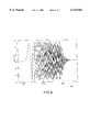
- FIG. 6 is a graph of a second embodiment of a GCR signal comprising the invention.
- FIG. 7 is a graph of the frequency spectrum of the GCR signal of FIG. 6.
- the characteristics of the communication channel (which include the echo artifacts, if any) must be determined at the receiver. From these characteristics, an inverse channel characteristic is derived in the form of a sequence of filter coefficients. These coefficients are then provided to filters which are used to implement the inverse channel processing, i.e. the echo cancellation.
- a received video signal contains echoes which are comprised of superimposed copies of the originally transmitted signal, which have different delay times and amplitudes.
- the strongest signal component represents the originally transmitted or main signal component. Looking in the time domain, any echo component occurring before the main signal component is called a "pre-echo” and any copy occurring after the main signal component is called a "post-echo”.
- FIG. 1 describes an echo cancellation circuit which can be used to cancel both types of echoes.
- a circuit can be part of a television receiver 2 which receives a television signal comprising the GCR signal. The signal is received by the tuner 6 of the receiver and converted to digital form using analog to digital converter 10.
- An IIR filter 20 is used to cancel post-echos and an FIR filter 15 is used to cancel pre-echoes. Echo cancellation circuits of this type are described in more detail in U.S. Pat. No. 5,161,017 which is specifically incorporated by reference herein.
- Video samples are received and input to A/D converter 10 and the GCR signal, which is transmitted during the vertical blanking interval of the television signal, is separated and fed to a buffer memory 30.
- the GCR signal which has been distorted according to the channel characteristics, is sometimes sampled over a number of frames, and an average of these samples is then fed to processor 25 which can be a microprocessor or a digital signal processor.
- the processor comprises a memory which contains a pre-processed and stored version of the GCR as transmitted, and the contents of buffer 30 is compared to the stored version of the GCR in processor 25 and from this comparison, the impulse response of the channel can be modeled.
- This channel model is then used to compute a sequence of coefficients for the filters which implement the inverse channel characteristic of the channel to suppress the echoes which are present.
- the parent application ('112) describes a method and apparatus for restoring a received signal wherein no assumptions are made about the communication channel characteristics other than that the signal and channel interaction is described by linear system theory. Consequently, the channel is characterized completely by its impulse response.
- the sequence of channel impulse response function samples thus obtained by processing the test signal serves to provide the correct sequence of coefficients to filters 15 and 20.
- the complete television signal is processed through these filters whereby the echo components are substantially reduced.
- the output of the IIR filter 20 is then fed to a digital-to-analog converter (D/A) 35 and presented as a video output signal to the video display of the receiver.
- D/A digital-to-analog converter
- the GCR signal is used to characterize the frequency or impulse response of the channel (including the transmitter and receiver, as well as the actual transmission path). It is therefore required that the frequency spectrum of the GCR signal used in a conventional television system must be low-pass and contained entirely in the 4.3 MHz. pass band of the NTSC signal. In addition, it must be as flat as possible in that band. If there is a null in the spectrum of the GCR signal, where the spectrum is near zero over some frequency interval, then the channel will not be adequately characterized over that interval. Even if there is a rolloff in the spectrum, where the spectrum is significantly less then the peak value, then in the presence of noise, the accuracy of the channel characterization will suffer for the frequencies where the rolloff occurs.
- FIG. 2 is a graph, in the time domain, of the BTA GCR signal. This is the signal as transmitted and as stored in ROM 10 and/or a processed version of which is stored in ROM 10. Before this signal is transmitted, it is integrated and inserted in the blanking interval of each field of the television signal.
- FIG. 3 When viewed in the frequency domain (FIG. 3) it is clear that the BTA GCR signal provides the necessary bandwidth characteristics for effective channel characterization.
- FIG. 2 When viewed in the time domain (FIG. 2) however, it can be seen that the amplitude versus time characteristic of the BTA GCR signal has relatively little energy. This results in poor performance in a noisy environment.
- the invention comprises an improved, non-cyclic GCR signal which features higher energy and improved energy distribution with respect to both time and frequency, and at the same time, the wide and flat bandwidth necessary for effective channel characterization.
- FIG. 4 is a graph of a first embodiment of the improved GCR signal. This GCR signal has a higher energy level with peaks more evenly distributed in time than the BTA GCR signal shown in FIG. 2.
- this GCR signal has a very flat spectrum in the band of interest and a higher energy level with respect to frequency (about eight times higher) than the BTA GCR signal shown in FIG. 3.
- W( ⁇ ) is a windowed window function
- a Hamming or Hanning window is used in this example however other windows can also be used.
- the parameters are in the range of from 0 to 10 12 .
- FIG. 6 is a graph of a second embodiment of the improved GCR signal. This GCR signal has a higher energy level with peaks more evenly distributed in time than the BTA GCR signal shown in FIG. 2.
- this GCR signal has a very flat spectrum in the band of interest and a higher energy level with respect to frequency (about ten times higher) than the BTA GCR signal shown in FIG. 3.
- a Hamming or Hanning window is used in this example however other windows can also be used.
- the parameters are in the range of from 0 to 10 12 .
Landscapes
- Engineering & Computer Science (AREA)
- Signal Processing (AREA)
- Multimedia (AREA)
- Computer Networks & Wireless Communication (AREA)
- Power Engineering (AREA)
- Physics & Mathematics (AREA)
- Mathematical Physics (AREA)
- Picture Signal Circuits (AREA)
- Cable Transmission Systems, Equalization Of Radio And Reduction Of Echo (AREA)
Abstract
An apparatus for receiving a television signal containing a ghost cancellation reference signal, and for using the reference signal to process the television signal so as to substantially eliminate path induced distortion.
Description
This application is a continuation of U.S. Ser. No. 08/699,277 filed on Aug. 19, 1996 which is a continuation of Ser. No. 07/949,284, Sep. 22, 1992, U.S. Pat. No. 5,568,202 which is itself a continuation of Ser. No. 07/831,600, Feb. 5, 1992, U.S. Pat. No. 5,179,444, which is a continuation of Ser. No. 07/698,521, May 10, 1991, U.S. Pat. No. 5,121,211, which is a continuation-in part of Ser. No. 07/693,737, Apr. 30, 1991, U.S. Pat. No. 5,111,298, which is a continuation-in part of Ser. No.07/595,112, Oct. 9, 1990, now abandoned.
In 1979 the IEEE published an article which has become a basic reference in the field of television echo (or "ghost") elimination. The article is entitled "A Tutorial On Ghost Cancellation in television Systems" and was written by Walter Ciciora, Gary Sgrignoli and William Thomas and it is incorporated by reference herein.
Although the Ciciora article described the fundamental principles, apparatus and algorithms applicable to ghost cancellation, the state of the art has only recently progressed to the point of providing practical ways to implement and improve these basic concepts.
There are two main steps to the echo cancellation process. First the characteristics of the communications channel (which include the echo artifacts, if any) must be determined by the receiver. Once the channel characteristics are calculated, filters are used to implement the inverse channel characteristics to substantially eliminate the echos. The present invention relates to an apparatus and an improved ghost cancellation reference signal, for identifying the characteristics of a communication channel.
Communication engineering continually must deal with the problem of restoring a signal which has been altered by the communication path over which the signal was transmitted. Signal restoration often can be achieved if the communication path is fully characterized, at least as to those parameters which contribute to the signal alteration. Thus, a frequently essential component of the signal restoration problem is that of identifying the characteristics of the communication path or channel.
A straight forward approach to the channel identification problem is to transmit a ghost cancellation reference signal (GCR) having a known characteristic, over the channel, and to receive the transmitted signal after it has passed through the channel. The originally transmitted signal is compared with the received signal, and a model of the channel characteristics is developed based on the comparison.
The Japanese Broadcasting Technology Association (BTA) has adopted a GCR signal that is the time integral of a windowed sin x/x pulse (sinc) which is transmitted on line 18 of the vertical blanking interval (VBI) of a television signal. Although the BTA GCR signal has the necessary flat bandwidth in the frequency domain, its energy is relatively low. The BTA GCR signal therefore may be suboptimal since its low energy limits its performance under high noise conditions. Additional processing time is needed to compensate for the noise present in the channel which increases the time it takes for the echo cancellation system to calculate the channel characteristics when conditions in the channel change. The BTA GCR signal has a fixed time interval which cannot be changed without effecting its frequency spectrum characteristics. This limits the possible applications for which the BTA GCR signal can be used. The time interval for an NTSC television system, for example, would be ≧52.5μs.
Other GCR signals have been proposed which have a higher energy level than the BTA signal. These signals, are cyclic in nature however, and therefore, not effective for detecting pre and post-echoes present in the channel.
The instant invention comprises a non-cyclic echo cancellation system which utilizes an improved, high energy non-cyclic GCR signal which provides the flat, wide frequency spectrum necessary to fully characterize the channel and which has a high energy level (amplitude) and a more even distribution of energy over a time interval. This time interval can be adjusted according to different system requirements while maintaining the necessary flat frequency response over the desired frequency range. The GCR signal of the invention can therefore be adapted for use in non-conventional television systems such as those providing high definition and enhanced definition television, as well as for other communication applications such as echo cancellation in telephony and microwave systems, for example.
FIG. 1 is a block diagram of one embodiment of an echo cancellation circuit comprising the invention;
FIG. 2 is a graph of the BTA GCR signal;
FIG. 3 is a graph of the frequency spectrum of the BTA GCR signal;
FIG. 4 is a graph of a first embodiment of a GCR signal comprising the invention;
FIG. 5 is a graph of the frequency spectrum of the GCR signal of FIG. 4;
FIG. 6 is a graph of a second embodiment of a GCR signal comprising the invention; and
FIG. 7 is a graph of the frequency spectrum of the GCR signal of FIG. 6.
There are normally two main steps involved in cancelling echoes which occur during the transmission of television signals. First the characteristics of the communication channel (which include the echo artifacts, if any) must be determined at the receiver. From these characteristics, an inverse channel characteristic is derived in the form of a sequence of filter coefficients. These coefficients are then provided to filters which are used to implement the inverse channel processing, i.e. the echo cancellation.
A received video signal contains echoes which are comprised of superimposed copies of the originally transmitted signal, which have different delay times and amplitudes. The strongest signal component represents the originally transmitted or main signal component. Looking in the time domain, any echo component occurring before the main signal component is called a "pre-echo" and any copy occurring after the main signal component is called a "post-echo".
FIG. 1 describes an echo cancellation circuit which can be used to cancel both types of echoes. Such a circuit can be part of a television receiver 2 which receives a television signal comprising the GCR signal. The signal is received by the tuner 6 of the receiver and converted to digital form using analog to digital converter 10. An IIR filter 20 is used to cancel post-echos and an FIR filter 15 is used to cancel pre-echoes. Echo cancellation circuits of this type are described in more detail in U.S. Pat. No. 5,161,017 which is specifically incorporated by reference herein.
Video samples are received and input to A/D converter 10 and the GCR signal, which is transmitted during the vertical blanking interval of the television signal, is separated and fed to a buffer memory 30. The GCR signal, which has been distorted according to the channel characteristics, is sometimes sampled over a number of frames, and an average of these samples is then fed to processor 25 which can be a microprocessor or a digital signal processor. The processor comprises a memory which contains a pre-processed and stored version of the GCR as transmitted, and the contents of buffer 30 is compared to the stored version of the GCR in processor 25 and from this comparison, the impulse response of the channel can be modeled. This channel model is then used to compute a sequence of coefficients for the filters which implement the inverse channel characteristic of the channel to suppress the echoes which are present.
The parent application ('112) describes a method and apparatus for restoring a received signal wherein no assumptions are made about the communication channel characteristics other than that the signal and channel interaction is described by linear system theory. Consequently, the channel is characterized completely by its impulse response.
The sequence of channel impulse response function samples thus obtained by processing the test signal, serves to provide the correct sequence of coefficients to filters 15 and 20. After the filter coefficients are fed to the filters, the complete television signal is processed through these filters whereby the echo components are substantially reduced. The output of the IIR filter 20 is then fed to a digital-to-analog converter (D/A) 35 and presented as a video output signal to the video display of the receiver.
The GCR signal is used to characterize the frequency or impulse response of the channel (including the transmitter and receiver, as well as the actual transmission path). It is therefore required that the frequency spectrum of the GCR signal used in a conventional television system must be low-pass and contained entirely in the 4.3 MHz. pass band of the NTSC signal. In addition, it must be as flat as possible in that band. If there is a null in the spectrum of the GCR signal, where the spectrum is near zero over some frequency interval, then the channel will not be adequately characterized over that interval. Even if there is a rolloff in the spectrum, where the spectrum is significantly less then the peak value, then in the presence of noise, the accuracy of the channel characterization will suffer for the frequencies where the rolloff occurs.
FIG. 2 is a graph, in the time domain, of the BTA GCR signal. This is the signal as transmitted and as stored in ROM 10 and/or a processed version of which is stored in ROM 10. Before this signal is transmitted, it is integrated and inserted in the blanking interval of each field of the television signal. When viewed in the frequency domain (FIG. 3) it is clear that the BTA GCR signal provides the necessary bandwidth characteristics for effective channel characterization. When viewed in the time domain (FIG. 2) however, it can be seen that the amplitude versus time characteristic of the BTA GCR signal has relatively little energy. This results in poor performance in a noisy environment.
The invention comprises an improved, non-cyclic GCR signal which features higher energy and improved energy distribution with respect to both time and frequency, and at the same time, the wide and flat bandwidth necessary for effective channel characterization.
FIG. 4 is a graph of a first embodiment of the improved GCR signal. This GCR signal has a higher energy level with peaks more evenly distributed in time than the BTA GCR signal shown in FIG. 2.
As shown in the frequency spectrum, FIG. 5, this GCR signal has a very flat spectrum in the band of interest and a higher energy level with respect to frequency (about eight times higher) than the BTA GCR signal shown in FIG. 3.
The equation which describes this embodiment of the GCR signal is: ##EQU1## where α, A, Cn, b and Ω are real parameters. where N is an integer parameter.
where W(ω) is a windowed window function.
A Hamming or Hanning window is used in this example however other windows can also be used.
The parameters are in the range of from 0 to 1012. For this example N=7, C1 =60, C3 =10, C5 =3, C7 =-1, Ceven =0, A=1 Ω=4.2×2×106 Rad (where Ω equals the end of the frequency band of interest, which in this case is 0 to 4.2 MHz.).
FIG. 6 is a graph of a second embodiment of the improved GCR signal. This GCR signal has a higher energy level with peaks more evenly distributed in time than the BTA GCR signal shown in FIG. 2.
As shown in the frequency spectrum, FIG. 7, this GCR signal has a very flat spectrum in the band of interest and a higher energy level with respect to frequency (about ten times higher) than the BTA GCR signal shown in FIG. 3.
The equation which describes this embodiment of the GCR signal is: ##EQU2## where A, b and Ω are real parameters; and where W(ω) is a windowed window function.
A Hamming or Hanning window is used in this example however other windows can also be used.
The parameters are in the range of from 0 to 1012. For this example A=1, b=0.0004 and Ω=4.2×2×106 Rad (where Ω equals the end of the frequency band of interest, which in this case is 0 is to 4.2 MHz.).
The foregoing disclosure and description of the invention is illustrative and explanatory thereof and various changes in the methods and apparatus indicated herein may be made within the scope of the appended claims without departing from the spirit of the invention.
Claims (3)
1. An apparatus for receiving a television signal which has been provided over a communications path and subjected to path induced distortion, said television signal comprising a reference signal, said apparatus comprising:
(a) a tuner means for receiving said television signal;
(b) an analog to digital converter for digitizing said television signal; and
(c) a processor means for separating from said digitized television signal, said reference signal as distorted by said communications path, and for generating from said distorted reference signal, a plurality of filter coefficients so as to substantially eliminate said path induced distortion from said received television signal;
wherein said reference signal at a point prior to its transmission over said communications path, is non-cyclic, has a substantially flat frequency response within the bandwidth of said communications path, and a plurality of substantially uniform amplitude peaks over a time interval.
2. The apparatus of claim 1 wherein said reference signal defined by the equation: ##EQU3## where A, b and Ω are real numbers; and where W(ω) is a windowed window function.
3. The apparatus of claim 1 wherein said reference signal defined by the equation: ##EQU4## where α, A, Cn, b and Ω are real numbers; where N is an integer; and
where W(ω) is a windowed window function.
Priority Applications (1)
| Application Number | Priority Date | Filing Date | Title |
|---|---|---|---|
| US09/065,794 US6133963A (en) | 1990-10-09 | 1998-04-23 | System for echo cancellation comprising an improved ghost cancellation reference signal |
Applications Claiming Priority (7)
| Application Number | Priority Date | Filing Date | Title |
|---|---|---|---|
| US07/595,112 US5047859A (en) | 1990-10-09 | 1990-10-09 | Method and apparatus for communication channel identification and signal restoration |
| US07/693,737 US5111298A (en) | 1990-10-09 | 1991-04-30 | Method and apparatus for communication channel identification and signal restoration |
| US07/698,521 US5121211A (en) | 1990-10-09 | 1991-05-10 | System for echo cancellation comprising an improved ghost cancellation reference signal |
| US07/831,600 US5179444A (en) | 1990-10-09 | 1992-02-05 | System for echo cancellation comprising an improved ghost cancellation reference signal |
| US07/949,284 US5568202A (en) | 1990-10-09 | 1992-09-22 | System for echo cancellation comprising an improved ghost cancellation reference signal |
| US69927796A | 1996-08-19 | 1996-08-19 | |
| US09/065,794 US6133963A (en) | 1990-10-09 | 1998-04-23 | System for echo cancellation comprising an improved ghost cancellation reference signal |
Related Parent Applications (1)
| Application Number | Title | Priority Date | Filing Date |
|---|---|---|---|
| US69927796A Continuation | 1990-10-09 | 1996-08-19 |
Publications (1)
| Publication Number | Publication Date |
|---|---|
| US6133963A true US6133963A (en) | 2000-10-17 |
Family
ID=27505025
Family Applications (3)
| Application Number | Title | Priority Date | Filing Date |
|---|---|---|---|
| US07/831,600 Expired - Lifetime US5179444A (en) | 1990-10-09 | 1992-02-05 | System for echo cancellation comprising an improved ghost cancellation reference signal |
| US07/949,284 Expired - Lifetime US5568202A (en) | 1990-10-09 | 1992-09-22 | System for echo cancellation comprising an improved ghost cancellation reference signal |
| US09/065,794 Expired - Lifetime US6133963A (en) | 1990-10-09 | 1998-04-23 | System for echo cancellation comprising an improved ghost cancellation reference signal |
Family Applications Before (2)
| Application Number | Title | Priority Date | Filing Date |
|---|---|---|---|
| US07/831,600 Expired - Lifetime US5179444A (en) | 1990-10-09 | 1992-02-05 | System for echo cancellation comprising an improved ghost cancellation reference signal |
| US07/949,284 Expired - Lifetime US5568202A (en) | 1990-10-09 | 1992-09-22 | System for echo cancellation comprising an improved ghost cancellation reference signal |
Country Status (1)
| Country | Link |
|---|---|
| US (3) | US5179444A (en) |
Families Citing this family (18)
| Publication number | Priority date | Publication date | Assignee | Title |
|---|---|---|---|---|
| US5179444A (en) * | 1990-10-09 | 1993-01-12 | North American Philips Corporation | System for echo cancellation comprising an improved ghost cancellation reference signal |
| US5278872A (en) * | 1991-05-28 | 1994-01-11 | North American Philips Corporation | System and circuit architecture for echo cancellation and a television receiver comprising same |
| US6937292B1 (en) | 1992-04-22 | 2005-08-30 | Samsung Electronics Co., Ltd. | Ghost cancellation reference signal with bessel chirps and PN sequences, and TV receiver using such signal |
| US5335009A (en) * | 1992-07-23 | 1994-08-02 | Industrial Technology Research Institute | Television broadcasting and receiving systems utilizing hybrid ghost reference signals in single field for fast ghost cancellation |
| US5285280A (en) * | 1993-03-19 | 1994-02-08 | Industrial Technology Research Institute | Division method and system for ghost cancellation |
| US5761088A (en) * | 1995-12-18 | 1998-06-02 | Philips Electronics North America Corporation | Method and apparatus for channel identification using incomplete or noisy information |
| FR2742956B1 (en) * | 1995-12-22 | 1998-01-30 | Thomson Multimedia Sa | CIRCUIT FOR PERFORMING DIGITAL NYQUIST FILTERING OF INTERMEDIATE FREQUENCY SIGNALS |
| JP3119584B2 (en) * | 1996-06-20 | 2000-12-25 | 日本電気株式会社 | Ghost removal device |
| US5886749A (en) * | 1996-12-13 | 1999-03-23 | Cable Television Laboratories, Inc. | Demodulation using a time domain guard interval with an overlapped transform |
| US6140822A (en) * | 1997-05-29 | 2000-10-31 | Williams; Thomas H. | System for signal path characterization with a reference signal using stepped-frequency increments |
| US6259891B1 (en) | 1997-09-04 | 2001-07-10 | Hughes Electronics Corporation | Adapter and method for use in a portable communication signal receiver system |
| US6507908B1 (en) * | 1999-03-04 | 2003-01-14 | Sun Microsystems, Inc. | Secure communication with mobile hosts |
| US6826279B1 (en) * | 2000-05-25 | 2004-11-30 | 3Com Corporation | Base band echo cancellation using laguerre echo estimation |
| US7184099B1 (en) | 2000-10-27 | 2007-02-27 | National Semiconductor Corporation | Controllable signal baseline and frequency emphasis circuit |
| US6911989B1 (en) | 2003-07-18 | 2005-06-28 | National Semiconductor Corporation | Halftone controller circuitry for video signal during on-screen-display (OSD) window |
| US7236203B1 (en) | 2004-04-22 | 2007-06-26 | National Semiconductor Corporation | Video circuitry for controlling signal gain and reference black level |
| TW201743570A (en) * | 2016-06-07 | 2017-12-16 | 晨星半導體股份有限公司 | Echo cancellation circuit, receiver applied in digital communication system and echo cancellation circuit method |
| US10567036B2 (en) * | 2018-06-19 | 2020-02-18 | Cisco Technology, Inc. | Echo cancellation to alleviate timing varying channels |
Citations (12)
| Publication number | Priority date | Publication date | Assignee | Title |
|---|---|---|---|---|
| US5047859A (en) * | 1990-10-09 | 1991-09-10 | North American Philips Corporation | Method and apparatus for communication channel identification and signal restoration |
| US5111298A (en) * | 1990-10-09 | 1992-05-05 | North American Philips Corporation | Method and apparatus for communication channel identification and signal restoration |
| US5121211A (en) * | 1990-10-09 | 1992-06-09 | North American Philips Corporation | System for echo cancellation comprising an improved ghost cancellation reference signal |
| US5161017A (en) * | 1990-04-04 | 1992-11-03 | U.S. Philips Corporation | Ghost cancellation circuit |
| US5179444A (en) * | 1990-10-09 | 1993-01-12 | North American Philips Corporation | System for echo cancellation comprising an improved ghost cancellation reference signal |
| US5345274A (en) * | 1993-01-25 | 1994-09-06 | Nec Corporation | Ghost canceling circuit promptly responsive to channel change |
| US5389977A (en) * | 1992-12-29 | 1995-02-14 | Samsung Electronics Co., Ltd. | Ghost canceler having a function of adaptively adjusting a signal level |
| US5396299A (en) * | 1991-05-28 | 1995-03-07 | North American Philips Corporation | System and circuit architecture for echo cancellation and a television receiver comprising same |
| US5623319A (en) * | 1995-10-05 | 1997-04-22 | Philips Electronics North American Corp. | Ghost cancellation reference signal detection and synchronization circuit |
| US5654766A (en) * | 1995-06-29 | 1997-08-05 | Philips Electronics North America Corporation | Television tuning systems and methods employing use of ghost cancellation and antenna directionality control to produce a ghost-free television signal |
| US5742356A (en) * | 1995-11-09 | 1998-04-21 | Denso Corporation | Mobile body TV receiver having optimal display frame pattern selection capability |
| US5761088A (en) * | 1995-12-18 | 1998-06-02 | Philips Electronics North America Corporation | Method and apparatus for channel identification using incomplete or noisy information |
Family Cites Families (7)
| Publication number | Priority date | Publication date | Assignee | Title |
|---|---|---|---|---|
| JPS5827475A (en) * | 1981-08-11 | 1983-02-18 | Hitachi Ltd | Ghost eliminating device |
| JPS6386968A (en) * | 1986-09-30 | 1988-04-18 | Toshiba Corp | Ghost eliminating device |
| JPS63185191A (en) * | 1987-01-27 | 1988-07-30 | Mitsubishi Electric Corp | Burst signal inserting device |
| JP2534737B2 (en) * | 1987-11-24 | 1996-09-18 | 日本電気ホームエレクトロニクス株式会社 | Filter circuit for ghost removal |
| US4864403A (en) * | 1988-02-08 | 1989-09-05 | Rca Licensing Corporation | Adaptive television ghost cancellation system including filter circuitry with non-integer sample delay |
| US4915557A (en) * | 1988-09-13 | 1990-04-10 | Rexnord Holdings Inc. | Captive screw assembly |
| US4980767A (en) * | 1989-11-30 | 1990-12-25 | At&T Bell Laboratories | Technique for determining signal dispersion characteristics in communications systems |
-
1992
- 1992-02-05 US US07/831,600 patent/US5179444A/en not_active Expired - Lifetime
- 1992-09-22 US US07/949,284 patent/US5568202A/en not_active Expired - Lifetime
-
1998
- 1998-04-23 US US09/065,794 patent/US6133963A/en not_active Expired - Lifetime
Patent Citations (13)
| Publication number | Priority date | Publication date | Assignee | Title |
|---|---|---|---|---|
| US5161017A (en) * | 1990-04-04 | 1992-11-03 | U.S. Philips Corporation | Ghost cancellation circuit |
| US5111298A (en) * | 1990-10-09 | 1992-05-05 | North American Philips Corporation | Method and apparatus for communication channel identification and signal restoration |
| US5121211A (en) * | 1990-10-09 | 1992-06-09 | North American Philips Corporation | System for echo cancellation comprising an improved ghost cancellation reference signal |
| US5179444A (en) * | 1990-10-09 | 1993-01-12 | North American Philips Corporation | System for echo cancellation comprising an improved ghost cancellation reference signal |
| US5568202A (en) * | 1990-10-09 | 1996-10-22 | North American Philips Corporation | System for echo cancellation comprising an improved ghost cancellation reference signal |
| US5047859A (en) * | 1990-10-09 | 1991-09-10 | North American Philips Corporation | Method and apparatus for communication channel identification and signal restoration |
| US5396299A (en) * | 1991-05-28 | 1995-03-07 | North American Philips Corporation | System and circuit architecture for echo cancellation and a television receiver comprising same |
| US5389977A (en) * | 1992-12-29 | 1995-02-14 | Samsung Electronics Co., Ltd. | Ghost canceler having a function of adaptively adjusting a signal level |
| US5345274A (en) * | 1993-01-25 | 1994-09-06 | Nec Corporation | Ghost canceling circuit promptly responsive to channel change |
| US5654766A (en) * | 1995-06-29 | 1997-08-05 | Philips Electronics North America Corporation | Television tuning systems and methods employing use of ghost cancellation and antenna directionality control to produce a ghost-free television signal |
| US5623319A (en) * | 1995-10-05 | 1997-04-22 | Philips Electronics North American Corp. | Ghost cancellation reference signal detection and synchronization circuit |
| US5742356A (en) * | 1995-11-09 | 1998-04-21 | Denso Corporation | Mobile body TV receiver having optimal display frame pattern selection capability |
| US5761088A (en) * | 1995-12-18 | 1998-06-02 | Philips Electronics North America Corporation | Method and apparatus for channel identification using incomplete or noisy information |
Non-Patent Citations (2)
| Title |
|---|
| "A Tutorial on Ghost Canceling in Television Systems" W. Ciciora et al, IEEE Transactions on Consumer Electronics, vol. CE-25, Feb., 1979. |
| A Tutorial on Ghost Canceling in Television Systems W. Ciciora et al, IEEE Transactions on Consumer Electronics, vol. CE 25, Feb., 1979. * |
Also Published As
| Publication number | Publication date |
|---|---|
| US5568202A (en) | 1996-10-22 |
| US5179444A (en) | 1993-01-12 |
Similar Documents
| Publication | Publication Date | Title |
|---|---|---|
| US5121211A (en) | System for echo cancellation comprising an improved ghost cancellation reference signal | |
| US6133963A (en) | System for echo cancellation comprising an improved ghost cancellation reference signal | |
| US5341177A (en) | System to cancel ghosts generated by multipath transmission of television signals | |
| EP0463781B1 (en) | Ghost cancellation technique for analog TV | |
| US5111298A (en) | Method and apparatus for communication channel identification and signal restoration | |
| KR0145307B1 (en) | A ghost cancelling circuit | |
| JPH06233156A (en) | Ghost-erasing reference signal trapping circuit used for tv receiver or video recorder | |
| KR960013223B1 (en) | Ghost Eliminator for TV Signal | |
| US5172232A (en) | Method and apparatus for communication channel identification and signal restoration | |
| JP2807628B2 (en) | Video receiver, communication system and ghost cancellation method | |
| US7304687B2 (en) | Ghost cancellation system using wavelet processed ghost cancellation reference signal | |
| HK1013388B (en) | A system for echo cancellation comprising a ghost cancellation reference signal | |
| US6462787B1 (en) | Digital ghost cancellation using teletext data lines | |
| KR0124177B1 (en) | Method for controlling quality of television using ghost canceller unit | |
| JPH0211069A (en) | Ghost removing device | |
| KR100292476B1 (en) | Circuit and method for reducing deghosting error of tv | |
| JP2525448B2 (en) | Ghost removal device | |
| JP3430087B2 (en) | Ghost removal device | |
| KR0129825B1 (en) | Ghost Eliminator | |
| KR960016564B1 (en) | Adaptive ghost cancelling apparatus | |
| KR940007159B1 (en) | Ghost erasing standard signal production and transmitter-receiver device in tv and the method of erasing ghost | |
| JPH0723256A (en) | Waveform equalizer | |
| JPH04100381A (en) | Waveform equalizer for tv receiver | |
| Gitlin et al. | GHOST CANCELLATION OF ANALOG TV SIGNALS: WITH APPLICATIONS TO IDTV, EDTV, AND HDTV |
Legal Events
| Date | Code | Title | Description |
|---|---|---|---|
| AS | Assignment |
Owner name: PHILIPS ELECTRONICS NORTH AMERICA CORPORATION, NEW Free format text: ASSIGNMENT OF ASSIGNORS INTEREST;ASSIGNOR:KOO, DAVID;REEL/FRAME:009164/0759 Effective date: 19980402 |
|
| STCF | Information on status: patent grant |
Free format text: PATENTED CASE |
|
| FPAY | Fee payment |
Year of fee payment: 4 |
|
| FPAY | Fee payment |
Year of fee payment: 8 |
|
| FPAY | Fee payment |
Year of fee payment: 12 |