US6132666A - Method for making formed fabric treatments - Google Patents
Method for making formed fabric treatments Download PDFInfo
- Publication number
- US6132666A US6132666A US08/885,745 US88574597A US6132666A US 6132666 A US6132666 A US 6132666A US 88574597 A US88574597 A US 88574597A US 6132666 A US6132666 A US 6132666A
- Authority
- US
- United States
- Prior art keywords
- lay
- treatment
- sheet
- undercut
- backing sheet
- Prior art date
- Legal status (The legal status is an assumption and is not a legal conclusion. Google has not performed a legal analysis and makes no representation as to the accuracy of the status listed.)
- Expired - Fee Related
Links
- 238000011282 treatment Methods 0.000 title claims abstract description 135
- 239000004744 fabric Substances 0.000 title claims abstract description 73
- 238000000034 method Methods 0.000 title claims description 62
- 239000000835 fiber Substances 0.000 claims abstract description 27
- 230000002093 peripheral effect Effects 0.000 claims abstract description 13
- 239000010410 layer Substances 0.000 claims description 58
- 238000000465 moulding Methods 0.000 claims description 56
- 239000000463 material Substances 0.000 claims description 24
- 239000012790 adhesive layer Substances 0.000 claims description 21
- 239000011230 binding agent Substances 0.000 claims description 8
- 239000004745 nonwoven fabric Substances 0.000 claims description 5
- 239000003063 flame retardant Substances 0.000 claims description 4
- 229920000728 polyester Polymers 0.000 abstract description 11
- 239000000853 adhesive Substances 0.000 abstract description 8
- 230000001070 adhesive effect Effects 0.000 abstract description 8
- 239000012528 membrane Substances 0.000 abstract description 6
- 239000002131 composite material Substances 0.000 abstract description 5
- 238000009434 installation Methods 0.000 description 11
- 230000003213 activating effect Effects 0.000 description 7
- 238000004519 manufacturing process Methods 0.000 description 5
- 239000004743 Polypropylene Substances 0.000 description 4
- 150000001336 alkenes Chemical class 0.000 description 4
- JRZJOMJEPLMPRA-UHFFFAOYSA-N olefin Natural products CCCCCCCC=C JRZJOMJEPLMPRA-UHFFFAOYSA-N 0.000 description 4
- -1 polypropylene Polymers 0.000 description 4
- 229920001155 polypropylene Polymers 0.000 description 4
- 239000000047 product Substances 0.000 description 4
- 230000000694 effects Effects 0.000 description 3
- 239000011094 fiberboard Substances 0.000 description 3
- 238000000926 separation method Methods 0.000 description 3
- 229910000831 Steel Inorganic materials 0.000 description 2
- 229910052782 aluminium Inorganic materials 0.000 description 2
- XAGFODPZIPBFFR-UHFFFAOYSA-N aluminium Chemical compound [Al] XAGFODPZIPBFFR-UHFFFAOYSA-N 0.000 description 2
- 230000015572 biosynthetic process Effects 0.000 description 2
- 239000012467 final product Substances 0.000 description 2
- 238000010438 heat treatment Methods 0.000 description 2
- 238000005192 partition Methods 0.000 description 2
- 239000004033 plastic Substances 0.000 description 2
- 229920003023 plastic Polymers 0.000 description 2
- 239000011347 resin Substances 0.000 description 2
- 229920005989 resin Polymers 0.000 description 2
- 239000010959 steel Substances 0.000 description 2
- 230000037303 wrinkles Effects 0.000 description 2
- 239000004820 Pressure-sensitive adhesive Substances 0.000 description 1
- 229910000639 Spring steel Inorganic materials 0.000 description 1
- 230000006978 adaptation Effects 0.000 description 1
- 230000003466 anti-cipated effect Effects 0.000 description 1
- 230000000712 assembly Effects 0.000 description 1
- 238000000429 assembly Methods 0.000 description 1
- 239000011093 chipboard Substances 0.000 description 1
- 238000001816 cooling Methods 0.000 description 1
- 238000013016 damping Methods 0.000 description 1
- 238000005034 decoration Methods 0.000 description 1
- 239000003000 extruded plastic Substances 0.000 description 1
- 239000003292 glue Substances 0.000 description 1
- 238000005286 illumination Methods 0.000 description 1
- 238000003754 machining Methods 0.000 description 1
- 238000012423 maintenance Methods 0.000 description 1
- 230000013011 mating Effects 0.000 description 1
- 239000011159 matrix material Substances 0.000 description 1
- 229910052751 metal Inorganic materials 0.000 description 1
- 239000002184 metal Substances 0.000 description 1
- 238000012986 modification Methods 0.000 description 1
- 230000004048 modification Effects 0.000 description 1
- 239000000843 powder Substances 0.000 description 1
- 238000003825 pressing Methods 0.000 description 1
- 238000003856 thermoforming Methods 0.000 description 1
- 238000009966 trimming Methods 0.000 description 1
- 125000000391 vinyl group Chemical group [H]C([*])=C([H])[H] 0.000 description 1
- 229920002554 vinyl polymer Polymers 0.000 description 1
- 230000000007 visual effect Effects 0.000 description 1
- 238000003466 welding Methods 0.000 description 1
- 239000002023 wood Substances 0.000 description 1
Images


Classifications
-
- E—FIXED CONSTRUCTIONS
- E04—BUILDING
- E04B—GENERAL BUILDING CONSTRUCTIONS; WALLS, e.g. PARTITIONS; ROOFS; FLOORS; CEILINGS; INSULATION OR OTHER PROTECTION OF BUILDINGS
- E04B9/00—Ceilings; Construction of ceilings, e.g. false ceilings; Ceiling construction with regard to insulation
- E04B9/04—Ceilings; Construction of ceilings, e.g. false ceilings; Ceiling construction with regard to insulation comprising slabs, panels, sheets or the like
- E04B9/0428—Ceilings; Construction of ceilings, e.g. false ceilings; Ceiling construction with regard to insulation comprising slabs, panels, sheets or the like having a closed frame around the periphery
-
- E—FIXED CONSTRUCTIONS
- E04—BUILDING
- E04B—GENERAL BUILDING CONSTRUCTIONS; WALLS, e.g. PARTITIONS; ROOFS; FLOORS; CEILINGS; INSULATION OR OTHER PROTECTION OF BUILDINGS
- E04B1/00—Constructions in general; Structures which are not restricted either to walls, e.g. partitions, or floors or ceilings or roofs
- E04B1/62—Insulation or other protection; Elements or use of specified material therefor
- E04B1/74—Heat, sound or noise insulation, absorption, or reflection; Other building methods affording favourable thermal or acoustical conditions, e.g. accumulating of heat within walls
- E04B1/82—Heat, sound or noise insulation, absorption, or reflection; Other building methods affording favourable thermal or acoustical conditions, e.g. accumulating of heat within walls specifically with respect to sound only
- E04B1/84—Sound-absorbing elements
- E04B1/8409—Sound-absorbing elements sheet-shaped
-
- E—FIXED CONSTRUCTIONS
- E04—BUILDING
- E04B—GENERAL BUILDING CONSTRUCTIONS; WALLS, e.g. PARTITIONS; ROOFS; FLOORS; CEILINGS; INSULATION OR OTHER PROTECTION OF BUILDINGS
- E04B2/00—Walls, e.g. partitions, for buildings; Wall construction with regard to insulation; Connections specially adapted to walls
- E04B2/74—Removable non-load-bearing partitions; Partitions with a free upper edge
- E04B2/7407—Removable non-load-bearing partitions; Partitions with a free upper edge assembled using frames with infill panels or coverings only; made-up of panels and a support structure incorporating posts
- E04B2/7416—Removable non-load-bearing partitions; Partitions with a free upper edge assembled using frames with infill panels or coverings only; made-up of panels and a support structure incorporating posts with free upper edge, e.g. for use as office space dividers
- E04B2/7422—Removable non-load-bearing partitions; Partitions with a free upper edge assembled using frames with infill panels or coverings only; made-up of panels and a support structure incorporating posts with free upper edge, e.g. for use as office space dividers with separate framed panels without intermediary support posts
-
- E—FIXED CONSTRUCTIONS
- E04—BUILDING
- E04B—GENERAL BUILDING CONSTRUCTIONS; WALLS, e.g. PARTITIONS; ROOFS; FLOORS; CEILINGS; INSULATION OR OTHER PROTECTION OF BUILDINGS
- E04B9/00—Ceilings; Construction of ceilings, e.g. false ceilings; Ceiling construction with regard to insulation
- E04B9/30—Ceilings; Construction of ceilings, e.g. false ceilings; Ceiling construction with regard to insulation characterised by edge details of the ceiling; e.g. securing to an adjacent wall
- E04B9/303—Ceilings; Construction of ceilings, e.g. false ceilings; Ceiling construction with regard to insulation characterised by edge details of the ceiling; e.g. securing to an adjacent wall for flexible tensioned membranes
-
- E—FIXED CONSTRUCTIONS
- E04—BUILDING
- E04B—GENERAL BUILDING CONSTRUCTIONS; WALLS, e.g. PARTITIONS; ROOFS; FLOORS; CEILINGS; INSULATION OR OTHER PROTECTION OF BUILDINGS
- E04B1/00—Constructions in general; Structures which are not restricted either to walls, e.g. partitions, or floors or ceilings or roofs
- E04B1/62—Insulation or other protection; Elements or use of specified material therefor
- E04B1/74—Heat, sound or noise insulation, absorption, or reflection; Other building methods affording favourable thermal or acoustical conditions, e.g. accumulating of heat within walls
- E04B1/82—Heat, sound or noise insulation, absorption, or reflection; Other building methods affording favourable thermal or acoustical conditions, e.g. accumulating of heat within walls specifically with respect to sound only
- E04B2001/8263—Mounting of acoustical elements on supporting structure, e.g. framework or wall surface
-
- E—FIXED CONSTRUCTIONS
- E04—BUILDING
- E04B—GENERAL BUILDING CONSTRUCTIONS; WALLS, e.g. PARTITIONS; ROOFS; FLOORS; CEILINGS; INSULATION OR OTHER PROTECTION OF BUILDINGS
- E04B1/00—Constructions in general; Structures which are not restricted either to walls, e.g. partitions, or floors or ceilings or roofs
- E04B1/62—Insulation or other protection; Elements or use of specified material therefor
- E04B1/74—Heat, sound or noise insulation, absorption, or reflection; Other building methods affording favourable thermal or acoustical conditions, e.g. accumulating of heat within walls
- E04B1/82—Heat, sound or noise insulation, absorption, or reflection; Other building methods affording favourable thermal or acoustical conditions, e.g. accumulating of heat within walls specifically with respect to sound only
- E04B1/84—Sound-absorbing elements
- E04B2001/8457—Solid slabs or blocks
- E04B2001/8461—Solid slabs or blocks layered
-
- E—FIXED CONSTRUCTIONS
- E04—BUILDING
- E04B—GENERAL BUILDING CONSTRUCTIONS; WALLS, e.g. PARTITIONS; ROOFS; FLOORS; CEILINGS; INSULATION OR OTHER PROTECTION OF BUILDINGS
- E04B2/00—Walls, e.g. partitions, for buildings; Wall construction with regard to insulation; Connections specially adapted to walls
- E04B2/74—Removable non-load-bearing partitions; Partitions with a free upper edge
- E04B2002/7479—Details of connection of flexible sheets to frame or posts
-
- E—FIXED CONSTRUCTIONS
- E04—BUILDING
- E04B—GENERAL BUILDING CONSTRUCTIONS; WALLS, e.g. PARTITIONS; ROOFS; FLOORS; CEILINGS; INSULATION OR OTHER PROTECTION OF BUILDINGS
- E04B2/00—Walls, e.g. partitions, for buildings; Wall construction with regard to insulation; Connections specially adapted to walls
- E04B2/74—Removable non-load-bearing partitions; Partitions with a free upper edge
- E04B2002/7488—Details of wiring
-
- E—FIXED CONSTRUCTIONS
- E04—BUILDING
- E04B—GENERAL BUILDING CONSTRUCTIONS; WALLS, e.g. PARTITIONS; ROOFS; FLOORS; CEILINGS; INSULATION OR OTHER PROTECTION OF BUILDINGS
- E04B2/00—Walls, e.g. partitions, for buildings; Wall construction with regard to insulation; Connections specially adapted to walls
- E04B2/74—Removable non-load-bearing partitions; Partitions with a free upper edge
- E04B2002/749—Partitions with screw-type jacks
-
- E—FIXED CONSTRUCTIONS
- E04—BUILDING
- E04B—GENERAL BUILDING CONSTRUCTIONS; WALLS, e.g. PARTITIONS; ROOFS; FLOORS; CEILINGS; INSULATION OR OTHER PROTECTION OF BUILDINGS
- E04B9/00—Ceilings; Construction of ceilings, e.g. false ceilings; Ceiling construction with regard to insulation
- E04B9/04—Ceilings; Construction of ceilings, e.g. false ceilings; Ceiling construction with regard to insulation comprising slabs, panels, sheets or the like
- E04B2009/0492—Ceilings; Construction of ceilings, e.g. false ceilings; Ceiling construction with regard to insulation comprising slabs, panels, sheets or the like with fabrics tensioned on frames
-
- Y—GENERAL TAGGING OF NEW TECHNOLOGICAL DEVELOPMENTS; GENERAL TAGGING OF CROSS-SECTIONAL TECHNOLOGIES SPANNING OVER SEVERAL SECTIONS OF THE IPC; TECHNICAL SUBJECTS COVERED BY FORMER USPC CROSS-REFERENCE ART COLLECTIONS [XRACs] AND DIGESTS
- Y10—TECHNICAL SUBJECTS COVERED BY FORMER USPC
- Y10T—TECHNICAL SUBJECTS COVERED BY FORMER US CLASSIFICATION
- Y10T156/00—Adhesive bonding and miscellaneous chemical manufacture
- Y10T156/10—Methods of surface bonding and/or assembly therefor
- Y10T156/1002—Methods of surface bonding and/or assembly therefor with permanent bending or reshaping or surface deformation of self sustaining lamina
- Y10T156/1043—Subsequent to assembly
- Y10T156/1044—Subsequent to assembly of parallel stacked sheets only
Definitions
- the outer layer of fabric applied to the structure i.e., the layer visible when the structure is in use
- a decorative or otherwise visible weave pattern which is directional in nature.
- the directional patterns are oriented precisely and consistently from structure to structure. If the structures are not carefully matched, any difference between the orientation of the pattern between two adjacent structures may be glaringly apparent and highly unattractive. Treatments typically are applied by stapling or otherwise affixing the fabric to the structure. As a result, it is difficult to precisely align the fabric on the structure in a consistent manner.
- step-like flanges are captured between the frame and top and bottom frame caps. This process creates a panel that is sufficiently rigid to be used without a pressed fiberboard backing and sufficiently light to allow easy manipulation and installation. Moreover, because the fabric is formed with the backing sheet, it is more easily and precisely aligned, thus reducing the likelihood of misaligned and unsightly installations.
- the fabric lay-up is made up of a layer of conventional, decorative, woven polyester fabric (of the type currently used in conventional fabric treatments), or fabrics comprising other synthetic or natural fibers, and a relatively stiff non-woven polyester fiber backing.
- the backing comprises non-woven fibers in a binder matrix.
- the non-woven fibers may include some proportion of an activating or heat-fusible fiber which works with the binder to allow the backing to be molded.
- the activating fiber is hardened by heat applied during the molding process, thus stiffening the formed lay-up and allowing it to hold a desired shape.
- Adjacent layers are not bonded prior to molding to allow slippage between the layers. This slippage allows the final product to attain its desired shape without wrinkling or pleating of the outer fabric at corners. The slippage also allows the proper formation of the undercut flanges and smooth corners.
- a heat- or pressure-activated adhesive layer is applied to the surface of one or both of the fabric layers so that layers are bonded together once the lay-up is conform
- the molding process creates a relatively stiff fabric and backing composite having a flange about the periphery of a central region. The edge of the flange forms an undercut lip. The process also creates smooth corners with no flap or pleat required to gather excess fabric.
- the structure to which such a treatment will be affixed is provided with a mounting lip about the area to be covered. The treatment is attached by pushing the undercut flange of the treatment over the mounting lip so that it "snaps" into place.
- the mounting lip may be formed with a spring-like structure that provides additional force to hold the treatment in place.
- Fabric treatments of the invention have many desirable characteristics. For instance, modular office dividers using the treatments are lighter than conventional office wall divider systems and permit substantial on-site assembly of the systems. Divider frames are simply bolted together or otherwise assembled from components on site. The cover panels are then "snapped" into position on the frames. The system is economical and facilitates easy removal and replacement of damaged fabric panels. Furthermore, it is unnecessary to use Tee-molding or other clamping arrangements, which may be expensive and time consuming to install, to hold fabric edges in place. Likewise, wall and window treatments, speaker grilles and lampshades are lighter, less complex and easier to install and replace.
- An additional object of the present invention is to provide molded fabric treatments which have relatively smooth corners with no flaps or noticeable folds.
- a further object of the present invention is to provide a means for affixing molded fabric treatments to the structure being treated without the need for fasteners.
- Another object of the present invention is to provide molded fabric treatment which may be "snapped" onto the structure being treated.
- Yet another object of the present invention is to provide modular office dividers which are easily assembled.
- An additional object of the present invention to provide modular office divider screens which are lightweight.
- Another object of the present invention to provide panels for modular office divider screens which are easily manufactured.
- Yet another object of the present invention to provide panels modular office divider screens which have a facing fabric which may be precisely aligned.
- An additional object of the present invention is to provide panels for modular office divider screens which may be manufactured with a minimum of selvage.
- FIG. 1 is a partial cross-sectional view of the fabric treatment in accordance with the present invention.
- FIG. 2 is a perspective of the treatment of FIG. 1 being installed on a structure.
- FIG. 3 is a cross-sectional view of a bladder press for forming the treatment of FIG. 1.
- FIG. 5 is a cross-sectional view of the bladder press of FIG. 3 with the bladder deflated.
- FIG. 6 is a cross-sectional view of the lay-up of the present invention.
- FIG. 8 is a top view of a tool for use with the bladder press of FIG. 3.
- FIG. 9 is an end view of the tool of FIG. 8.
- FIG. 10 is a top view of a tool for use with the bladder press of FIG. 3.
- FIG. 11 is an end view of the tool of FIG. 10.
- FIG. 12 is a partial cross-section of the tool of FIG. 7.
- FIG. 13 is a perspective view of the tool of FIG. 12 with a lay-up partially in place for molding.
- FIG. 14 is a perspective view of the tool of FIG. 12 showing the fabric treatment of the invention molded thereto.
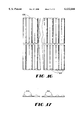
- FIG. 15 is a partial perspective view of the tool of FIG. 12 showing the corner portion with the fabric treatment molded thereto.
- FIG. 17 is a side view of the mold of FIG. 16.
- FIG. 19 is a perspective view of a modular office divider assembly in accordance with the present invention.
- FIG. 20 is an exploded perspective view of two sections of the assembly of FIG. 19.
- FIG. 21 is a perspective view of a portion of the rail of the frame of FIG. 20.
- FIG. 22 is a partial cross-sectional view of the frame of FIG. 19
- FIG. 23 is a partial cross-sectional view of an alternate embodiment of the lip of the rail of FIG. 19.
- FIG. 27 is a partial side view of the assembly of FIG. 19.
- FIG. 28 is a partial cross-sectional view of the assembly of FIG. 19.
- FIG. 29 is a perspective view of an alternative embodiment of a modular office divider assembly in accordance with the present invention.
- FIG. 30 is a partial cross-sectional view of the assembly of FIG. 28.
- structure 22 which may be an office divider, speaker cabinet, lampshade, window or wall treatment, or any other structure to which it may be desirable to affix a fabric treatment, includes mounting lip 24 which is complimentary in shape and size to the combination of flange 18 and lip 20. Flange 18 and lip 20 are "snapped" over mounting lip 24, thereby affixing treatment 10 to structure 22.
- Facing layer 26 is a conventional, decorative, woven polyester fabric, or another synthetic or natural fiber fabric.
- backing layer 28 extends over the entirety of treatment 10. This is desirable if treatment 10 is to have decorative or structural features in central portion 12, or if it is desired that all of treatment 10 be stiff and/or relatively rigid. In some applications, such as speaker grilles, such structural or decorative aspects may not be desired. In such cases, backing layer 28 need only be present about the periphery of treatment 10 to allow the formation of flange 18 and lip 20, and protruding into central portion 12 only enough to allow affixing portion 14 to work properly.
- FIGS. 3-5 show the molding process for forming fabric treatments.
- a conventional bladder mold 42 of the type typically used to bond vinyl coverings on to cabinet doors, tabletops and moldings is provided.
- Lay-up 40 is placed in bladder mold 42.
- bladder 46 is deflated and bed 44 is moved out of mold 42 and allowed to cool. Typically the process applies about 5.5 bars of pressure at 180 degrees Celsius for one hundred and twenty to one hundred and sixty seconds. Of course, these parameters may be varied depending on the materials selected and the desired results. Excess material, or "selvage" may then be trimmed to produce the final formed fabric treatment 10. Selvage may then be recycled for use in forming new sheets or other products.
- the interior space between two treatments 10 may be filled with batting 136 in order to provide certain characteristics which may be desired, such as sound attenuation or flame retardance.
Abstract
Description
Claims (41)
Priority Applications (11)
| Application Number | Priority Date | Filing Date | Title |
|---|---|---|---|
| US08/885,745 US6132666A (en) | 1997-06-30 | 1997-06-30 | Method for making formed fabric treatments |
| DE69837260T DE69837260T2 (en) | 1997-06-30 | 1998-06-18 | Method for forming fabric coverings and fabric coverings |
| CN98808632.8A CN1268988A (en) | 1997-06-30 | 1998-06-18 | Moulded fabric cover |
| CA002294157A CA2294157A1 (en) | 1997-06-30 | 1998-06-18 | Formed fabric treatments |
| ES98931388T ES2284208T3 (en) | 1997-06-30 | 1998-06-18 | TEXTILE MATERIAL AND METHOD TREATMENT TO OBTAIN THE SAME. |
| AU81533/98A AU8153398A (en) | 1997-06-30 | 1998-06-18 | Moulded fabric covers |
| AT98931388T ATE356262T1 (en) | 1997-06-30 | 1998-06-18 | FABRIC LINING AND METHOD FOR PRODUCING SAME |
| JP11505607A JP2000515451A (en) | 1997-06-30 | 1998-06-18 | Molded fabric cover |
| BR9810494-2A BR9810494A (en) | 1997-06-30 | 1998-06-18 | Molded fabric covers. |
| PCT/US1998/012756 WO1999000562A1 (en) | 1997-06-30 | 1998-06-18 | Moulded fabric covers |
| EP98931388A EP0993531B1 (en) | 1997-06-30 | 1998-06-18 | Fabric treatment and method for making the same |
Applications Claiming Priority (1)
| Application Number | Priority Date | Filing Date | Title |
|---|---|---|---|
| US08/885,745 US6132666A (en) | 1997-06-30 | 1997-06-30 | Method for making formed fabric treatments |
Publications (1)
| Publication Number | Publication Date |
|---|---|
| US6132666A true US6132666A (en) | 2000-10-17 |
Family
ID=25387599
Family Applications (1)
| Application Number | Title | Priority Date | Filing Date |
|---|---|---|---|
| US08/885,745 Expired - Fee Related US6132666A (en) | 1997-06-30 | 1997-06-30 | Method for making formed fabric treatments |
Country Status (11)
| Country | Link |
|---|---|
| US (1) | US6132666A (en) |
| EP (1) | EP0993531B1 (en) |
| JP (1) | JP2000515451A (en) |
| CN (1) | CN1268988A (en) |
| AT (1) | ATE356262T1 (en) |
| AU (1) | AU8153398A (en) |
| BR (1) | BR9810494A (en) |
| CA (1) | CA2294157A1 (en) |
| DE (1) | DE69837260T2 (en) |
| ES (1) | ES2284208T3 (en) |
| WO (1) | WO1999000562A1 (en) |
Cited By (24)
| Publication number | Priority date | Publication date | Assignee | Title |
|---|---|---|---|---|
| US6619003B2 (en) | 2002-01-23 | 2003-09-16 | Quanex Corporation | Method of assembling a frame assembly for a partition system |
| US20030233810A1 (en) * | 2002-06-21 | 2003-12-25 | Martin Wildeman | Office panel and fabric covering therefor |
| US6722096B2 (en) | 2002-01-23 | 2004-04-20 | Quanex Corporation | Frame assembly and frame component for tensioning fabric about a panel of a partition system |
| US6821367B1 (en) | 2003-03-31 | 2004-11-23 | Steelcase Development Corporation | Ultrasonic tool and method for securing a covering to a frame |
| US20050012234A1 (en) * | 2003-06-18 | 2005-01-20 | Kindig Alan L. | Method for making cushioned products with an integral cover |
| US20060080919A1 (en) * | 2004-10-14 | 2006-04-20 | Dykstra Thomas L | Fabric/rail attachment process |
| FR2881205A1 (en) * | 2005-01-26 | 2006-07-28 | Abel Lallemand | Edging and connection units assembly for obtaining panel, has connection units each connected to two edging units after assembling edging units with flexible part, while being tensioned to exert force for spacing edging units` adjacent ends |
| US20060213916A1 (en) * | 2005-03-22 | 2006-09-28 | Brown Eric R | Molded fiber lid for a container |
| EP1724532A1 (en) * | 2005-05-12 | 2006-11-22 | ETS Dienstleistungs- und Handels GmbH | Facing for cornered three-dimensional room elements for interiors |
| US20080168723A1 (en) * | 2006-12-24 | 2008-07-17 | Bilge Henry H | System for mounting wall panels to a wall structure |
| US20080283177A1 (en) * | 2006-12-04 | 2008-11-20 | Glain Michael L | Tensioning device for composite structures |
| US20080302490A1 (en) * | 2007-06-06 | 2008-12-11 | Wilson Eric P | Screen frame and assembly |
| US20090065963A1 (en) * | 2007-09-11 | 2009-03-12 | Spirit Aerosystems, Inc. | Method and apparatus for tensioning composite material |
| US20100190431A1 (en) * | 2009-01-23 | 2010-07-29 | Darius Kurniawan | Hvac system including a noise-reducing feature |
| US7934494B1 (en) * | 2003-10-10 | 2011-05-03 | Donna Gail Schneider | Collapsible heating apparatus |
| US8534752B2 (en) | 2010-06-02 | 2013-09-17 | Steelcase Inc. | Reconfigurable table assemblies |
| CN104775585A (en) * | 2015-04-30 | 2015-07-15 | 孙高雷 | Method for producing flexible building decorative board |
| US9140017B1 (en) | 2014-04-11 | 2015-09-22 | Sportsfield Intellectual, Llc | Reversible resilient wall padding apparatus and methods for releasably attaching same to a wall |
| US9670673B2 (en) * | 2015-11-09 | 2017-06-06 | Awi Licensing Llc | Ceiling system |
| US10039374B2 (en) | 2016-05-13 | 2018-08-07 | Steelcase Inc. | Multi-tiered workstation assembly |
| US20180297816A1 (en) * | 2015-10-08 | 2018-10-18 | Otis Elevator Company | Renewable panel assembly for an elevator car |
| US10517392B2 (en) | 2016-05-13 | 2019-12-31 | Steelcase Inc. | Multi-tiered workstation assembly |
| US10681980B2 (en) | 2010-06-02 | 2020-06-16 | Steelcase Inc. | Frame type workstation configurations |
| US20220167744A1 (en) * | 2020-12-02 | 2022-06-02 | Steelcase Inc. | Privacy barrier with window |
Families Citing this family (17)
| Publication number | Priority date | Publication date | Assignee | Title |
|---|---|---|---|---|
| FR2793504B1 (en) * | 1999-05-11 | 2001-11-09 | Jean Marc Scherrer | CEILING SLAB |
| DE10234317B4 (en) * | 2002-07-26 | 2006-02-09 | Rentex Wand- Und Deckensysteme Gmbh | Ceiling or wall system and profile for foil covering |
| ITUD20040111A1 (en) * | 2004-05-26 | 2004-08-26 | Studioart Srl | COATING ELEMENT |
| DE102007001376B4 (en) | 2007-01-09 | 2009-04-16 | Greiner, Switbert, Dr. | Membrane element and method for covering surfaces |
| DE102008045487A1 (en) * | 2008-09-03 | 2010-03-25 | Erich Diel | Frame of a sound absorber and sound absorber |
| CN101929202B (en) * | 2009-06-19 | 2012-06-27 | 詹德威 | Heat-preservation cold-resistance sound-insulation device and hollow bearing wall construction method using same |
| ITCN20090007A1 (en) * | 2009-07-24 | 2011-01-25 | Mabel S R L | ORNAMENTAL SYSTEM FOR THE ELEMENTS AND COMPLEMENTS OF FURNISHING IN GENERAL THAT ALLOWS THE SUBSTITUTION OR INTERCHANGEABILITY OF THE DECORATIVE MATERIAL IN A SIMPLE AND EFFECTIVE MANNER WITHOUT ANY SCREW, GLUE OR OTHER TYPE OF WELDING |
| IT1399419B1 (en) * | 2010-04-08 | 2013-04-16 | Valcucine Spa | "MODULAR DOOR" |
| CN102547495B (en) * | 2010-12-21 | 2016-07-20 | 北京爱德发科技有限公司 | A kind of have the audio amplifier and assembling jig thereof and method that weave veil |
| CN102423916B (en) * | 2011-11-22 | 2013-09-11 | 天津工业大学 | Preparation method and product of single polylactic acid composite material |
| CN104039200B (en) * | 2011-12-08 | 2017-09-22 | 赫尔曼米勒有限公司 | Compound body-support component and its method for manufacture |
| CN102729488B (en) * | 2012-07-05 | 2013-05-08 | 中联重科股份有限公司 | Carbon fiber composite arm rest, method for manufacturing same and concrete pump truck including same |
| FR2996239B1 (en) * | 2012-09-28 | 2015-03-13 | Normalu | MIRROR-FORMED WALL SLAB AND METHOD OF MAKING SAME |
| CN105852535A (en) * | 2016-06-14 | 2016-08-17 | 江苏佰家丽新材料科技有限公司 | Surface treatment method for polyester fiber sound-absorbing screen connector |
| EP3543417A1 (en) | 2018-03-23 | 2019-09-25 | Kvadrat Soft Cells A/S | Fabric mounting system and method of mounting and tensioning fabric |
| BE1027085B1 (en) * | 2019-03-01 | 2020-09-28 | Casalis Bvpa | DETACHABLE FIXABLE COVER FOR ACOUSTIC PANEL |
| CN109822955A (en) * | 2019-03-21 | 2019-05-31 | 东莞市佳栓实业有限公司 | A kind of bob-weight dynamic balance massage type buffering convection current air bag cushion and its production technology |
Citations (54)
| Publication number | Priority date | Publication date | Assignee | Title |
|---|---|---|---|---|
| US1209308A (en) * | 1913-03-27 | 1916-12-19 | Edmond Lanhoffer | Apparatus for molding objects by pressure. |
| US1438966A (en) * | 1918-08-26 | 1922-12-19 | Barrett Co | Construction material |
| US2363323A (en) * | 1941-12-17 | 1944-11-21 | Westinghouse Electric & Mfg Co | High-pressure laminated material |
| US2385083A (en) * | 1942-11-17 | 1945-09-18 | Kemerer Don Charles | Forming method |
| US2406628A (en) * | 1944-01-20 | 1946-08-27 | Local Ind Inc | Apparatus for forming skis, etc. |
| US2418438A (en) * | 1944-11-17 | 1947-04-01 | Vilas E Watts | Method for producing curved laminated structures |
| US2458864A (en) * | 1945-01-01 | 1949-01-11 | John D Lindsay | Method of making integral molded structures |
| US2524932A (en) * | 1946-09-12 | 1950-10-10 | Westinghouse Electric Corp | Process for producing bonded mica |
| US2532442A (en) * | 1942-03-09 | 1950-12-05 | Daly Le Grand | Molded article |
| US3307990A (en) * | 1962-12-03 | 1967-03-07 | West Point Pepperell Inc | Method of making a composite product |
| US3328927A (en) * | 1964-10-29 | 1967-07-04 | Watson Mfg Company Inc | Paneling for elevator cabs |
| US3408239A (en) * | 1965-06-11 | 1968-10-29 | Coast Mfg & Supply Company | Method for manufacturing glass fiber reinforced resin impregnated mats |
| US3428506A (en) * | 1965-01-11 | 1969-02-18 | Hercules Inc | Method of producing a needled,nonwoven fibrous structure |
| US3608264A (en) * | 1969-09-04 | 1971-09-28 | Owens Corning Fiberglass Corp | Molded fibrous surfacing unit |
| US3706171A (en) * | 1971-04-02 | 1972-12-19 | Harry I Shayman | Decorative acoustical ceiling panel |
| US3831330A (en) * | 1972-03-14 | 1974-08-27 | Steelcase Inc | Panel system |
| US3993828A (en) * | 1973-02-16 | 1976-11-23 | Akzona Incorporated | Polyester, fiberglass-reinforced composite laminate |
| US4123879A (en) * | 1977-06-27 | 1978-11-07 | American Seating Company | Panel wall systems with modular component build-up |
| US4135341A (en) * | 1977-06-20 | 1979-01-23 | Armstrong Cork Company | Roll-on ceiling for manufactured homes |
| US4144924A (en) * | 1978-03-31 | 1979-03-20 | Steelcase Inc. | Panel connector system |
| US4169176A (en) * | 1978-08-05 | 1979-09-25 | Firma Carl Freudenberg | Process for the manufacture of heat shaped automobile carpet |
| US4199635A (en) * | 1979-04-20 | 1980-04-22 | Albany International Corp. | Fabric faced laminate panel and method of manufacture |
| US4214646A (en) * | 1978-06-19 | 1980-07-29 | Conwed Corporation | Space divider and acoustic panel |
| US4219598A (en) * | 1974-08-06 | 1980-08-26 | Sanyo Electric Co., Ltd. | Molded article, the method for manufacturing the same and the dies therefor |
| US4251104A (en) * | 1979-02-19 | 1981-02-17 | Britax Weathershields Limited | Mounting ring for sunshine roof assembly |
| US4258093A (en) * | 1979-04-26 | 1981-03-24 | Brunswick Corporation | Molding nonwoven, needle punched fabrics into three dimensional shapes |
| US4277531A (en) * | 1979-08-06 | 1981-07-07 | Ppg Industries, Inc. | High strength fiber glass reinforced thermoplastic sheets and method of manufacturing same involving a reverse barb needling procedure |
| US4282283A (en) * | 1979-10-29 | 1981-08-04 | Textured Products, Inc. | Laminated fiberglass fabric |
| US4302499A (en) * | 1978-06-01 | 1981-11-24 | Armco Inc. | Moldable composite |
| US4307145A (en) * | 1981-02-11 | 1981-12-22 | Goldman Daniel S | Decorative fabric and method of making the same |
| US4359132A (en) * | 1981-05-14 | 1982-11-16 | Albany International Corp. | High performance speaker diaphragm |
| US4373001A (en) * | 1982-04-05 | 1983-02-08 | Albany International Corp. | Molded textile air conditioning and heat duct |
| US4391865A (en) * | 1981-10-05 | 1983-07-05 | Constance Lillie B | Thermal drapery construction |
| US4424250A (en) * | 1982-04-21 | 1984-01-03 | Albany International Corp. | Carpet faced textile panel |
| US4428454A (en) * | 1981-09-24 | 1984-01-31 | Capaul Raymond W | Acoustical panel construction |
| DE3229884A1 (en) * | 1982-08-11 | 1984-02-16 | Dr. Alois Stankiewicz Schallschluck GmbH & Co KG, 3101 Adelheidsdorf | Process and device for forming and/or joining films |
| US4432822A (en) * | 1982-04-08 | 1984-02-21 | Albany International Corp. | Method of manufacturing upholstery panels |
| US4445954A (en) * | 1983-02-09 | 1984-05-01 | Albany International Corp. | Method of manufacturing molded upholstery panels |
| US4474840A (en) * | 1981-08-27 | 1984-10-02 | The Gates Corporation | Method of selective bonding of textile materials |
| US4491617A (en) * | 1982-11-24 | 1985-01-01 | Bay Mills Limited | Reinforcing composite for roofing membranes and process for making such composites |
| US4515848A (en) * | 1983-09-23 | 1985-05-07 | Gates Formed Fibre Products Inc. | Materials and methods for making resin-rigidified articles |
| US4581272A (en) * | 1985-01-11 | 1986-04-08 | Gates Formed-Fibre Products, Inc. | Automotive vehicle door kick panel and method of manufacture |
| US4581453A (en) * | 1982-05-28 | 1986-04-08 | Bayer Aktiengesellschaft | Guanidinothiazole derivatives containing alkylene bridges, and their use for influencing lipid metabolism |
| US4635410A (en) * | 1985-04-17 | 1987-01-13 | Chumbley James F | Decorative fabric wall system |
| EP0234473A2 (en) * | 1986-02-28 | 1987-09-02 | Metzeler Schaum Gmbh | Method of positioning a flat article in a mould for in situ foaming |
| US4726987A (en) * | 1987-04-03 | 1988-02-23 | Gates Formed-Fibre Products, Inc. | Fire retardant structural textile panel |
| US4744189A (en) * | 1986-08-14 | 1988-05-17 | Snap-Wall, Inc. | Removable wall panel |
| US4838380A (en) * | 1986-09-10 | 1989-06-13 | Burlington Industries, Inc. | Nylon impression fabric-acoustical application |
| CA2018516A1 (en) * | 1989-12-14 | 1991-06-14 | Carl W. Andersen | Formed partition panel and method |
| US5086606A (en) * | 1991-02-20 | 1992-02-11 | Krueger International, Inc. | Office panel partition and frame therefore |
| US5121578A (en) * | 1991-01-28 | 1992-06-16 | Holz Plastics, Inc. | Slat wall decorating system |
| US5238515A (en) * | 1991-11-07 | 1993-08-24 | Haworth, Inc. | Fabric securement method |
| US5265333A (en) * | 1989-08-25 | 1993-11-30 | Hunter Douglas International N.V. | Method of forming a self sustained cladding panel |
| US5298694A (en) * | 1993-01-21 | 1994-03-29 | Minnesota Mining And Manufacturing Company | Acoustical insulating web |
-
1997
- 1997-06-30 US US08/885,745 patent/US6132666A/en not_active Expired - Fee Related
-
1998
- 1998-06-18 ES ES98931388T patent/ES2284208T3/en not_active Expired - Lifetime
- 1998-06-18 AU AU81533/98A patent/AU8153398A/en not_active Abandoned
- 1998-06-18 JP JP11505607A patent/JP2000515451A/en active Pending
- 1998-06-18 EP EP98931388A patent/EP0993531B1/en not_active Expired - Lifetime
- 1998-06-18 CN CN98808632.8A patent/CN1268988A/en active Pending
- 1998-06-18 AT AT98931388T patent/ATE356262T1/en not_active IP Right Cessation
- 1998-06-18 CA CA002294157A patent/CA2294157A1/en not_active Abandoned
- 1998-06-18 BR BR9810494-2A patent/BR9810494A/en not_active Application Discontinuation
- 1998-06-18 WO PCT/US1998/012756 patent/WO1999000562A1/en active IP Right Grant
- 1998-06-18 DE DE69837260T patent/DE69837260T2/en not_active Expired - Fee Related
Patent Citations (55)
| Publication number | Priority date | Publication date | Assignee | Title |
|---|---|---|---|---|
| US1209308A (en) * | 1913-03-27 | 1916-12-19 | Edmond Lanhoffer | Apparatus for molding objects by pressure. |
| US1438966A (en) * | 1918-08-26 | 1922-12-19 | Barrett Co | Construction material |
| US2363323A (en) * | 1941-12-17 | 1944-11-21 | Westinghouse Electric & Mfg Co | High-pressure laminated material |
| US2532442A (en) * | 1942-03-09 | 1950-12-05 | Daly Le Grand | Molded article |
| US2385083A (en) * | 1942-11-17 | 1945-09-18 | Kemerer Don Charles | Forming method |
| US2406628A (en) * | 1944-01-20 | 1946-08-27 | Local Ind Inc | Apparatus for forming skis, etc. |
| US2418438A (en) * | 1944-11-17 | 1947-04-01 | Vilas E Watts | Method for producing curved laminated structures |
| US2458864A (en) * | 1945-01-01 | 1949-01-11 | John D Lindsay | Method of making integral molded structures |
| US2524932A (en) * | 1946-09-12 | 1950-10-10 | Westinghouse Electric Corp | Process for producing bonded mica |
| US3307990A (en) * | 1962-12-03 | 1967-03-07 | West Point Pepperell Inc | Method of making a composite product |
| US3328927A (en) * | 1964-10-29 | 1967-07-04 | Watson Mfg Company Inc | Paneling for elevator cabs |
| US3428506A (en) * | 1965-01-11 | 1969-02-18 | Hercules Inc | Method of producing a needled,nonwoven fibrous structure |
| US3408239A (en) * | 1965-06-11 | 1968-10-29 | Coast Mfg & Supply Company | Method for manufacturing glass fiber reinforced resin impregnated mats |
| US3608264A (en) * | 1969-09-04 | 1971-09-28 | Owens Corning Fiberglass Corp | Molded fibrous surfacing unit |
| US3706171A (en) * | 1971-04-02 | 1972-12-19 | Harry I Shayman | Decorative acoustical ceiling panel |
| US3831330A (en) * | 1972-03-14 | 1974-08-27 | Steelcase Inc | Panel system |
| US3993828A (en) * | 1973-02-16 | 1976-11-23 | Akzona Incorporated | Polyester, fiberglass-reinforced composite laminate |
| US4219598A (en) * | 1974-08-06 | 1980-08-26 | Sanyo Electric Co., Ltd. | Molded article, the method for manufacturing the same and the dies therefor |
| US4135341A (en) * | 1977-06-20 | 1979-01-23 | Armstrong Cork Company | Roll-on ceiling for manufactured homes |
| US4123879A (en) * | 1977-06-27 | 1978-11-07 | American Seating Company | Panel wall systems with modular component build-up |
| US4144924A (en) * | 1978-03-31 | 1979-03-20 | Steelcase Inc. | Panel connector system |
| US4302499A (en) * | 1978-06-01 | 1981-11-24 | Armco Inc. | Moldable composite |
| US4214646A (en) * | 1978-06-19 | 1980-07-29 | Conwed Corporation | Space divider and acoustic panel |
| US4169176A (en) * | 1978-08-05 | 1979-09-25 | Firma Carl Freudenberg | Process for the manufacture of heat shaped automobile carpet |
| US4251104A (en) * | 1979-02-19 | 1981-02-17 | Britax Weathershields Limited | Mounting ring for sunshine roof assembly |
| US4199635A (en) * | 1979-04-20 | 1980-04-22 | Albany International Corp. | Fabric faced laminate panel and method of manufacture |
| US4258093A (en) * | 1979-04-26 | 1981-03-24 | Brunswick Corporation | Molding nonwoven, needle punched fabrics into three dimensional shapes |
| US4277531A (en) * | 1979-08-06 | 1981-07-07 | Ppg Industries, Inc. | High strength fiber glass reinforced thermoplastic sheets and method of manufacturing same involving a reverse barb needling procedure |
| US4282283A (en) * | 1979-10-29 | 1981-08-04 | Textured Products, Inc. | Laminated fiberglass fabric |
| US4307145A (en) * | 1981-02-11 | 1981-12-22 | Goldman Daniel S | Decorative fabric and method of making the same |
| US4359132A (en) * | 1981-05-14 | 1982-11-16 | Albany International Corp. | High performance speaker diaphragm |
| US4474840A (en) * | 1981-08-27 | 1984-10-02 | The Gates Corporation | Method of selective bonding of textile materials |
| US4428454A (en) * | 1981-09-24 | 1984-01-31 | Capaul Raymond W | Acoustical panel construction |
| US4391865A (en) * | 1981-10-05 | 1983-07-05 | Constance Lillie B | Thermal drapery construction |
| US4373001A (en) * | 1982-04-05 | 1983-02-08 | Albany International Corp. | Molded textile air conditioning and heat duct |
| US4432822A (en) * | 1982-04-08 | 1984-02-21 | Albany International Corp. | Method of manufacturing upholstery panels |
| US4424250A (en) * | 1982-04-21 | 1984-01-03 | Albany International Corp. | Carpet faced textile panel |
| US4581453A (en) * | 1982-05-28 | 1986-04-08 | Bayer Aktiengesellschaft | Guanidinothiazole derivatives containing alkylene bridges, and their use for influencing lipid metabolism |
| DE3229884A1 (en) * | 1982-08-11 | 1984-02-16 | Dr. Alois Stankiewicz Schallschluck GmbH & Co KG, 3101 Adelheidsdorf | Process and device for forming and/or joining films |
| US4491617A (en) * | 1982-11-24 | 1985-01-01 | Bay Mills Limited | Reinforcing composite for roofing membranes and process for making such composites |
| US4445954A (en) * | 1983-02-09 | 1984-05-01 | Albany International Corp. | Method of manufacturing molded upholstery panels |
| US4515848A (en) * | 1983-09-23 | 1985-05-07 | Gates Formed Fibre Products Inc. | Materials and methods for making resin-rigidified articles |
| US4581272A (en) * | 1985-01-11 | 1986-04-08 | Gates Formed-Fibre Products, Inc. | Automotive vehicle door kick panel and method of manufacture |
| US4635410A (en) * | 1985-04-17 | 1987-01-13 | Chumbley James F | Decorative fabric wall system |
| EP0234473A2 (en) * | 1986-02-28 | 1987-09-02 | Metzeler Schaum Gmbh | Method of positioning a flat article in a mould for in situ foaming |
| US4744189A (en) * | 1986-08-14 | 1988-05-17 | Snap-Wall, Inc. | Removable wall panel |
| US4838380A (en) * | 1986-09-10 | 1989-06-13 | Burlington Industries, Inc. | Nylon impression fabric-acoustical application |
| US4726987A (en) * | 1987-04-03 | 1988-02-23 | Gates Formed-Fibre Products, Inc. | Fire retardant structural textile panel |
| US5265333A (en) * | 1989-08-25 | 1993-11-30 | Hunter Douglas International N.V. | Method of forming a self sustained cladding panel |
| CA2018516A1 (en) * | 1989-12-14 | 1991-06-14 | Carl W. Andersen | Formed partition panel and method |
| US5111579A (en) * | 1989-12-14 | 1992-05-12 | Steelcase Inc. | Method for making a frameless acoustic cover panel |
| US5121578A (en) * | 1991-01-28 | 1992-06-16 | Holz Plastics, Inc. | Slat wall decorating system |
| US5086606A (en) * | 1991-02-20 | 1992-02-11 | Krueger International, Inc. | Office panel partition and frame therefore |
| US5238515A (en) * | 1991-11-07 | 1993-08-24 | Haworth, Inc. | Fabric securement method |
| US5298694A (en) * | 1993-01-21 | 1994-03-29 | Minnesota Mining And Manufacturing Company | Acoustical insulating web |
Non-Patent Citations (1)
| Title |
|---|
| International Search Report of PCT/US98/12756 (Aug. 28, 1998). * |
Cited By (45)
| Publication number | Priority date | Publication date | Assignee | Title |
|---|---|---|---|---|
| US6619003B2 (en) | 2002-01-23 | 2003-09-16 | Quanex Corporation | Method of assembling a frame assembly for a partition system |
| US6722096B2 (en) | 2002-01-23 | 2004-04-20 | Quanex Corporation | Frame assembly and frame component for tensioning fabric about a panel of a partition system |
| US20030233810A1 (en) * | 2002-06-21 | 2003-12-25 | Martin Wildeman | Office panel and fabric covering therefor |
| US6821367B1 (en) | 2003-03-31 | 2004-11-23 | Steelcase Development Corporation | Ultrasonic tool and method for securing a covering to a frame |
| US20050012234A1 (en) * | 2003-06-18 | 2005-01-20 | Kindig Alan L. | Method for making cushioned products with an integral cover |
| US7934494B1 (en) * | 2003-10-10 | 2011-05-03 | Donna Gail Schneider | Collapsible heating apparatus |
| US20060080919A1 (en) * | 2004-10-14 | 2006-04-20 | Dykstra Thomas L | Fabric/rail attachment process |
| FR2881205A1 (en) * | 2005-01-26 | 2006-07-28 | Abel Lallemand | Edging and connection units assembly for obtaining panel, has connection units each connected to two edging units after assembling edging units with flexible part, while being tensioned to exert force for spacing edging units` adjacent ends |
| WO2006079705A1 (en) * | 2005-01-26 | 2006-08-03 | Abel Lallemand | Arrangement of elements for producing a panel |
| US7810287B2 (en) | 2005-01-26 | 2010-10-12 | Abel Lallemand | Arrangement of elements for producing a panel |
| US20080110583A1 (en) * | 2005-01-26 | 2008-05-15 | Abel Lallemand | Arrangement of Elements for Producing a Panel |
| US20060213916A1 (en) * | 2005-03-22 | 2006-09-28 | Brown Eric R | Molded fiber lid for a container |
| US20100019413A1 (en) * | 2005-03-22 | 2010-01-28 | Brown Eric R | Molded fiber lid for a container |
| EP1724532A1 (en) * | 2005-05-12 | 2006-11-22 | ETS Dienstleistungs- und Handels GmbH | Facing for cornered three-dimensional room elements for interiors |
| US20080283177A1 (en) * | 2006-12-04 | 2008-11-20 | Glain Michael L | Tensioning device for composite structures |
| US8944128B2 (en) | 2006-12-04 | 2015-02-03 | The Boeing Company | Device for tensioning a preform |
| US8303757B2 (en) | 2006-12-04 | 2012-11-06 | The Boeing Company | Tensioning device for composite structures |
| US20080168723A1 (en) * | 2006-12-24 | 2008-07-17 | Bilge Henry H | System for mounting wall panels to a wall structure |
| US7621084B2 (en) * | 2006-12-24 | 2009-11-24 | Bilge Henry H | System for mounting wall panels to a wall structure |
| US7740048B2 (en) * | 2007-06-06 | 2010-06-22 | Wilson Eric P | Screen frame and assembly |
| US20080302490A1 (en) * | 2007-06-06 | 2008-12-11 | Wilson Eric P | Screen frame and assembly |
| US7717694B2 (en) | 2007-09-11 | 2010-05-18 | Spirit Aerosystems, Inc. | Method and apparatus for tensioning composite material |
| US20090065963A1 (en) * | 2007-09-11 | 2009-03-12 | Spirit Aerosystems, Inc. | Method and apparatus for tensioning composite material |
| US9581353B2 (en) * | 2009-01-23 | 2017-02-28 | Valeo Climate Control Corporation | HVAC system including a noise-reducing feature |
| US20100190431A1 (en) * | 2009-01-23 | 2010-07-29 | Darius Kurniawan | Hvac system including a noise-reducing feature |
| US11930926B2 (en) | 2010-06-02 | 2024-03-19 | Steelcase Inc. | Frame type workstation configurations |
| US10681980B2 (en) | 2010-06-02 | 2020-06-16 | Steelcase Inc. | Frame type workstation configurations |
| US11317716B2 (en) | 2010-06-02 | 2022-05-03 | Steelcase Inc. | Frame type workstation configurations |
| US11882934B2 (en) | 2010-06-02 | 2024-01-30 | Steelcase Inc. | Frame type workstation configurations |
| US11944194B2 (en) | 2010-06-02 | 2024-04-02 | Steelcase Inc. | Frame type workstation configurations |
| US8534752B2 (en) | 2010-06-02 | 2013-09-17 | Steelcase Inc. | Reconfigurable table assemblies |
| US9140017B1 (en) | 2014-04-11 | 2015-09-22 | Sportsfield Intellectual, Llc | Reversible resilient wall padding apparatus and methods for releasably attaching same to a wall |
| US9909321B2 (en) | 2014-04-11 | 2018-03-06 | Sportsfield Intellectual, Llc | Reversible resilient wall padding apparatus and methods for releasably attaching same to a wall |
| CN104775585A (en) * | 2015-04-30 | 2015-07-15 | 孙高雷 | Method for producing flexible building decorative board |
| CN106193494B (en) * | 2015-04-30 | 2018-09-11 | 宁波高新区起兴机电有限公司 | A kind of production method of soft decorative panel for building |
| CN106193496B (en) * | 2015-04-30 | 2018-09-11 | 宁波高新区起兴机电有限公司 | A kind of production method of soft decorative panel for building |
| CN104775585B (en) * | 2015-04-30 | 2018-01-26 | 陶健 | A kind of production method of soft decorative panel for building |
| CN106193494A (en) * | 2015-04-30 | 2016-12-07 | 孙高雷 | A kind of production method of soft decorative panel for building |
| CN106193496A (en) * | 2015-04-30 | 2016-12-07 | 孙高雷 | A kind of production method of soft decorative panel for building |
| US20180297816A1 (en) * | 2015-10-08 | 2018-10-18 | Otis Elevator Company | Renewable panel assembly for an elevator car |
| US10196816B2 (en) | 2015-11-09 | 2019-02-05 | Awi Licensing Llc | Ceiling system |
| US9670673B2 (en) * | 2015-11-09 | 2017-06-06 | Awi Licensing Llc | Ceiling system |
| US10517392B2 (en) | 2016-05-13 | 2019-12-31 | Steelcase Inc. | Multi-tiered workstation assembly |
| US10039374B2 (en) | 2016-05-13 | 2018-08-07 | Steelcase Inc. | Multi-tiered workstation assembly |
| US20220167744A1 (en) * | 2020-12-02 | 2022-06-02 | Steelcase Inc. | Privacy barrier with window |
Also Published As
| Publication number | Publication date |
|---|---|
| EP0993531A1 (en) | 2000-04-19 |
| EP0993531B1 (en) | 2007-03-07 |
| CA2294157A1 (en) | 1999-01-07 |
| ES2284208T3 (en) | 2007-11-01 |
| DE69837260T2 (en) | 2007-11-15 |
| DE69837260D1 (en) | 2007-04-19 |
| WO1999000562A1 (en) | 1999-01-07 |
| ATE356262T1 (en) | 2007-03-15 |
| BR9810494A (en) | 2000-09-12 |
| JP2000515451A (en) | 2000-11-21 |
| AU8153398A (en) | 1999-01-19 |
| CN1268988A (en) | 2000-10-04 |
Similar Documents
| Publication | Publication Date | Title |
|---|---|---|
| US6132666A (en) | Method for making formed fabric treatments | |
| DE60120678T2 (en) | SUCCESSIVE STRUCTURAL PANEL | |
| US5715638A (en) | Fabric wall panel system | |
| US5111579A (en) | Method for making a frameless acoustic cover panel | |
| US6722096B2 (en) | Frame assembly and frame component for tensioning fabric about a panel of a partition system | |
| CA1041268A (en) | Fabric wall coverings | |
| US7370454B2 (en) | Door skin, method of manufacturing a door produced therewith, and door produced therefrom | |
| CA2520654C (en) | Reverse molded plant-on panel component, method of manufacture, and method of decorating a door therewith | |
| KR20170005081A (en) | Panel systems and methods | |
| JPH04128018A (en) | Method for forming formed plastic panel with insert | |
| US6619003B2 (en) | Method of assembling a frame assembly for a partition system | |
| US20050081467A1 (en) | Elements of stretched false ceiling, use of same for producing false walls and false ceilings | |
| US6385939B1 (en) | Bullnose cladding system | |
| TW288086B (en) | ||
| US6951592B2 (en) | Method of forming a fabric covered pad for wall panel | |
| US7329456B2 (en) | Method of fabrication of an acoustical substrate into a three dimensional product | |
| EP1541375A3 (en) | Flooring system with a plurality of different decorative upper surfaces | |
| MXPA99011943A (en) | Moulded fabric covers | |
| US20020011380A1 (en) | Projection screen and projection screen system | |
| JP4698060B2 (en) | Ceiling membrane material mounting structure | |
| CN211846789U (en) | Concatenation formula furred ceiling | |
| US5601896A (en) | Fabric-covered board structure and process of manufacture | |
| KR100597001B1 (en) | Stretch sheet establish construction for the ceiling panel | |
| GB2271960A (en) | Mouldable self-supporting reinforced material | |
| DE10246413A1 (en) | Folding wall or room divider comprises a sandwich structure with core and facing skins produced in a single molding operation |
Legal Events
| Date | Code | Title | Description |
|---|---|---|---|
| AS | Assignment |
Owner name: INTERFACE, INC., GEORGIA Free format text: ASSIGNMENT OF ASSIGNORS INTEREST;ASSIGNORS:FOLEY, WILLIAM H.;NEWHOUSE, THOMAS J.;REEL/FRAME:008671/0027 Effective date: 19970627 |
|
| AS | Assignment |
Owner name: WACHOVIA BANK, NATIONAL ASSOCIATION, GEORGIA Free format text: SECURITY INTEREST;ASSIGNOR:INTERFACE, INC.;REEL/FRAME:014910/0414 Effective date: 20031218 Owner name: WACHOVIA BANK, NATIONAL ASSOCIATION,GEORGIA Free format text: SECURITY INTEREST;ASSIGNOR:INTERFACE, INC.;REEL/FRAME:014910/0414 Effective date: 20031218 |
|
| FPAY | Fee payment |
Year of fee payment: 4 |
|
| AS | Assignment |
Owner name: WACHOVIA BANK, NATIONAL ASSOCIATION, GEORGIA Free format text: RELEASE OF PATENT SECURITY INTEREST;ASSIGNOR:INTERFACE, INC.;REEL/FRAME:019658/0418 Effective date: 20070716 |
|
| AS | Assignment |
Owner name: INTERFACEFABRIC INC., DELAWARE Free format text: ASSIGNMENT OF ASSIGNORS INTEREST;ASSIGNOR:INTERFACE, INC.;REEL/FRAME:019679/0484 Effective date: 20070627 |
|
| AS | Assignment |
Owner name: WACHOVIA CAPITAL FINANCE CORPORATION (NEW ENGLAND) Free format text: SECURITY AGREEMENT;ASSIGNOR:INTERFACEFABRIC, INC.;REEL/FRAME:019843/0108 Effective date: 20070831 |
|
| AS | Assignment |
Owner name: LBC CREDIT PARTNERS, L.P., PENNSYLVANIA Free format text: SECURITY AGREEMENT;ASSIGNOR:INTERFACEFABRIC, INC.;REEL/FRAME:020166/0328 Effective date: 20070831 |
|
| REMI | Maintenance fee reminder mailed | ||
| LAPS | Lapse for failure to pay maintenance fees | ||
| STCH | Information on status: patent discontinuation |
Free format text: PATENT EXPIRED DUE TO NONPAYMENT OF MAINTENANCE FEES UNDER 37 CFR 1.362 |
|
| FP | Lapsed due to failure to pay maintenance fee |
Effective date: 20081017 |
|
| AS | Assignment |
Owner name: TRUE TEXTILES, INC., F/K/A INTERFACEFABRIC, INC., Free format text: RELEASE BY SECURED PARTY;ASSIGNOR:WELLS FARGO CAPITAL FINANCE, LLC, SUCCESSOR BY MERGER TO WACHOVIA CAPITAL FINANCE CORPORATION (NEW ENGLAND), AS AGENT;REEL/FRAME:027669/0861 Effective date: 20120207 |