US6131885A - Plastic, T-shaped fence post - Google Patents
Plastic, T-shaped fence post Download PDFInfo
- Publication number
- US6131885A US6131885A US08/909,286 US90928697A US6131885A US 6131885 A US6131885 A US 6131885A US 90928697 A US90928697 A US 90928697A US 6131885 A US6131885 A US 6131885A
- Authority
- US
- United States
- Prior art keywords
- post
- shaped
- tongue
- plastic
- assembly according
- Prior art date
- Legal status (The legal status is an assumption and is not a legal conclusion. Google has not performed a legal analysis and makes no representation as to the accuracy of the status listed.)
- Expired - Fee Related
Links
Images


Classifications
-
- E—FIXED CONSTRUCTIONS
- E04—BUILDING
- E04H—BUILDINGS OR LIKE STRUCTURES FOR PARTICULAR PURPOSES; SWIMMING OR SPLASH BATHS OR POOLS; MASTS; FENCING; TENTS OR CANOPIES, IN GENERAL
- E04H17/00—Fencing, e.g. fences, enclosures, corrals
- E04H17/02—Wire fencing, e.g. made of wire mesh
- E04H17/06—Parts for wire fences
-
- E—FIXED CONSTRUCTIONS
- E01—CONSTRUCTION OF ROADS, RAILWAYS, OR BRIDGES
- E01F—ADDITIONAL WORK, SUCH AS EQUIPPING ROADS OR THE CONSTRUCTION OF PLATFORMS, HELICOPTER LANDING STAGES, SIGNS, SNOW FENCES, OR THE LIKE
- E01F13/00—Arrangements for obstructing or restricting traffic, e.g. gates, barricades ; Preventing passage of vehicles of selected category or dimensions
- E01F13/02—Arrangements for obstructing or restricting traffic, e.g. gates, barricades ; Preventing passage of vehicles of selected category or dimensions free-standing; portable, e.g. for guarding open manholes ; Portable signs or signals specially adapted for fitting to portable barriers
- E01F13/028—Flexible barrier members, e.g. cords; Means for rendering same conspicuous; Adapted supports, e.g. with storage reel
-
- E—FIXED CONSTRUCTIONS
- E01—CONSTRUCTION OF ROADS, RAILWAYS, OR BRIDGES
- E01F—ADDITIONAL WORK, SUCH AS EQUIPPING ROADS OR THE CONSTRUCTION OF PLATFORMS, HELICOPTER LANDING STAGES, SIGNS, SNOW FENCES, OR THE LIKE
- E01F9/00—Arrangement of road signs or traffic signals; Arrangements for enforcing caution
- E01F9/60—Upright bodies, e.g. marker posts or bollards; Supports for road signs
- E01F9/658—Upright bodies, e.g. marker posts or bollards; Supports for road signs characterised by means for fixing
- E01F9/673—Upright bodies, e.g. marker posts or bollards; Supports for road signs characterised by means for fixing for holding sign posts or the like
- E01F9/685—Subsoil means, e.g. foundations
-
- E—FIXED CONSTRUCTIONS
- E04—BUILDING
- E04H—BUILDINGS OR LIKE STRUCTURES FOR PARTICULAR PURPOSES; SWIMMING OR SPLASH BATHS OR POOLS; MASTS; FENCING; TENTS OR CANOPIES, IN GENERAL
- E04H12/00—Towers; Masts or poles; Chimney stacks; Water-towers; Methods of erecting such structures
- E04H12/22—Sockets or holders for poles or posts
- E04H12/2207—Sockets or holders for poles or posts not used
- E04H12/2215—Sockets or holders for poles or posts not used driven into the ground
-
- E—FIXED CONSTRUCTIONS
- E04—BUILDING
- E04H—BUILDINGS OR LIKE STRUCTURES FOR PARTICULAR PURPOSES; SWIMMING OR SPLASH BATHS OR POOLS; MASTS; FENCING; TENTS OR CANOPIES, IN GENERAL
- E04H17/00—Fencing, e.g. fences, enclosures, corrals
- E04H17/02—Wire fencing, e.g. made of wire mesh
- E04H17/10—Wire fencing, e.g. made of wire mesh characterised by the way of connecting wire to posts; Droppers
- E04H17/12—Wire fencing, e.g. made of wire mesh characterised by the way of connecting wire to posts; Droppers the wire being placed in slots, grooves, or the like
Definitions
- the present invention relates to fence posts, in particular a plastic fence post for use in electric fencing systems.
- Non-metallic fence posts for use in electric fencing systems are generally known from U.S. Pat. Nos. 4,046,356, 4,070,007, 3,977,653, 3,464,671, 2,861,122, and 2,821,365.
- These conventional fence posts suffer from a major disadvantage because no provision is made for adjusting the height of the fence posts so as to permit adjustment in the height of fence. Being able to adjust the height of a new or existing fence is a desirable feature as it allows the fence to be altered to the changing needs of a user.
- any height adjustable fence post should be easy to assemble and use, permitting fast and easy alterations in the fence height.
- U.S. Pat. No. 5,395,093 to Chrisman provides an extender for use in extending the height of metallic fence posts.
- the use of the Chrisman extender involves a complicated deformation procedure of the extender before it can be used.
- further securement of the extender to the fence posts is generally required after the posts are inserted into the extender.
- the fence posts and extender of Chrisman are relatively heavy and prone to rusting. To change the height of an existing post, the extender of Chrisman must be first installed over the end of the post before another post can be added thereto.
- fence posts generally utilize systems for securing fencing members or strands, e.g. electric wire or tape, barbed wire, etc., thereto at spaced locations along the posts.
- systems for securing however are generally designed with a single type of fencing member in mind and do not allow for a wide range of fencing materials to be secured to the posts.
- the general purpose of the present invention is to provide a non-metallic fence post, for use in electric fences, which can be quickly and easily adjusted in height to permit changes in the height of the fence, and which can be used with different types of fencing materials.
- a preferred embodiment of a fence post assembly in accordance with the principles of the present invention includes an elongated, T-shaped plastic lower post member having one end adapted for insertion into the ground and an opposite end having a T-shaped slot formed therein.
- a plastic upper member includes a tongue extending therefrom which is secured within the T-shaped slot so as to secure the upper member to the lower post member.
- the tongue is T-shaped, and a pin extends through aligned holes in the end of the lower post member and the T-shaped tongue in order to fasten the upper and lower members together.
- the upper member is a fence post that is secured to the lower post member. Therefore the height of the fence can be increased by disposing the tongue of the upper post within the T-shaped slot, and using the pin to secure the posts together.
- the upper member is a fence post cap having a T-shape tongue that is disposed within the T-shaped slot and secured by the pin.
- the cap thus closes off the slot, preventing material from building up in the slot, and provides a flat top surface to facilitate insertion of the post into the ground.
- a chain support member having a hook at each end is secured by the cap to the lower post member to enable a chain or the like to be hung between adjacent fence posts.
- the T-shaped slot, T-shaped tongue, and pin provide a fast and easy way to permit adjustments to the height of the fence.
- each holder clip includes a first portion rigidly attached to the post member and a second, moveable portion disposed over the first portion and in selective engagement therewith.
- the first and second portions define a loop therebetween at one end of the holder clip for holding a slender strand member, such as wire or rope.
- the first and second portions further define an elongated area therebetween for holding a relatively wide strand member, such as tape, therein.
- the second, moveable portion includes a finger extending therefrom toward the first portion, and the first portion includes a notch that receives the finger when the second portion is engaged with the first portion.
- the finger separates the loop from the elongated area, to prevent movement of the strand member from its area.
- the first portion includes a tapered locking shoulder at one end and the second portion includes a tapered locking tab at an end that corresponds to the one end, so as to form a selectively releasable connection between the first portion and the second portion.
- a finger actuated tab is connected to the tapered locking tab for releasing the connection between the locking tab and the locking shoulder.
- FIG. 1 is a perspective view of the lower post member showing how the post cap and chain support member connect thereto.
- FIG. 2 is a perspective view of the lower post member and upper post member, and how they connect together.
- FIG. 3 is a perspective view of the lower post member and upper post member connected together.
- FIG. 4 is a view of one side of the lower post member.
- FIG. 5 is a view of another side of the lower post member.
- FIG. 6 is a view of one side of the upper post member.
- FIG. 7 is a view of another side of the upper post member.
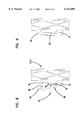
- FIG. 8 is a detailed view of a rail holder clip in an open position.
- FIG. 9 is a view similar to FIG. 8, but showing the clip in a closed position.
- a fence post system or assembly including a lower post member 10, and either an upper post member 12 or a post cap 14.
- the lower post member 10 is elongated, and includes a head portion 16 and a stem portion 18 intersecting the head portion perpendicular thereto, thus forming generally a "T" shape.
- the member 10 is formed from a generally rigid plastic or composite material so that it is non-conducting, and can have any desirable length, such as about 25 inches (63.5 cm).
- the stem portion 18 is a latticed structure between the ends of the post member. It should be noted that in the illustrated embodiment, web portions are provided between the ribs of the latticed structure, that is the lattice structure is not open. This provides added strength to the post member.
- the head portion 16 includes a stiffening rib 17 extending therealong for stiffening the member 10.
- the lower end of the member 10 includes a beveled section 20 with a pointed tip 22 and a foot platform 24 extending from the head portion 16 and located at the end of the beveled section, in order to facilitate insertion of the post member into the ground.
- the user simply uses his foot to apply pressure to the foot platform 24 in order to drive the post member into the ground.
- the platform 24 is integrally formed with the post member 10 and is suitably stiffened relative thereto to prevent deformation of the platform.
- the opposite, upper end 26 of the member 10 is generally thickened or enlarged, as best seen in FIGS. 4-5, with the lattice structure thereof filled in, so as to increase the strength of the upper end.
- a T-shaped slot 28 is formed through the thickened end 26 extending downward toward the lower end for a pre-determined length, such that the head of the slot is formed in the head portion 16 of the end 26 and the stem of the slot is formed in the stem portion 18 of the end.
- the slot 28 is thus able to receive the upper post member 12 or the cap 14 therein for either extending the length of the post or closing off the slot.
- the end 26 also includes an aperture 30 extending through the thickened stem portion 18 and intersecting the stem portion of the slot 28. Also formed in the end 26 is a notch 32 that extends across the thickened stem portion 18 adjacent the head portion 16, the purpose of which will be later described.
- the upper post member 12 is secured to the lower post member 10.
- the upper post member 12 is similar to the member 10 in that it is elongated and includes a head portion 34 and a stem portion 36 giving the member 12 an overall "T" shape.
- the member 12 is formed from a generally rigid plastic or composite material so that it is non-conducting, and has a length such that when attached to the lower member, a fence post of desired size, for instance about 48 inches (121.92 cm), is obtained.
- the stem portion 36 is also latticed between the ends of the post member, in the same manner as post member 10, in order to reduce weight, while the head portion 34 includes a stiffening rib 38 extending therealong for stiffening the member 12.
- the lower end of the member 12 is formed as a non-latticed T-shaped tongue 40 which is sized and shaped for insertion into the T-shaped slot 28.
- the stem of the tongue 40 includes an aperture 42 therethrough that aligns with the aperture 30 when the tongue is inserted.
- a plastic locking pin 44 is inserted into the aligned apertures in order to retain the tongue with the slot.
- the pin 44 is preferably bifurcated and flanged at one end to permit removal of the pin once inserted, and is headed at the opposite end.
- the tongue 40 also includes a tab 45 extending from each side of the stem portion thereof, which is adpated to fit within the notch 32 on the end 26 of the member 10 to provide additional securement of the upper member 12 to the lower member.
- the upper end of the member 12 is closed by a post cap 46 forming a flat top surface of the member 12.
- the post cap 14 is secured to the end 26 of the lower member 10.
- the post cap 14, as best shown in FIG. 1, is also formed from plastic or composite material, and includes a flat top portion 48 and a T-shaped tongue 50 extending from the bottom of the portion 48 that is sized and shaped for insertion into the T-shaped slot 28.
- the head of the tongue 50 is separated from the stem of the tongue by a notch 52 which aligns with the notch 32.
- the stem of the tongue 50 further includes an aperture 54 therethrough which aligns with the aperture 30. The pin 44 is then inserted into the apertures 30,54 to secure the tongue 50 within the slot.
- a chain support member 56 is disposed within the aligned notches 32,52 in order to enable a chain, or the like, to be hung between adjacent fence posts.
- the member 56 includes an intermediate portion 58 sized and shaped to snugly fit within the notches, and a pair of hook members 60,62 extending from opposite ends of the portion 58 in a general direction towards an adjacent post. A loop of the chain can thus be hung on one of the hooks 60,62, and a loop hung on a hook on an adjacent post, in order to hang the chain between the posts.
- the posts 10,12 include strand holder clips 64 at spaced locations along the length of each post member. As illustrated, there are two clips on each post member, although a smaller or larger number of clips could be used.
- the holder clips 64 are generally made of the same material as the post members 10,12, such as plastic, in order to be able to support electric strand members without conducting electricity.
- the holder clips can be integrally formed with the posts during formation of the posts, or secured to the posts after formation thereof.
- the holder clips are disposed on the head portions 16,34 of the T-shaped posts, on the same side 10 of the posts as the foot platform 24.
- each holder clip 64 includes a first portion 66 rigidly secured to the head portion of the post members and a second, moveable portion 68 generally doubled back over the first portion so as to form a loop 70 at one end of the holder clip for holding a slender strand member, such as electric wire, barbed wire, or rope.
- a slender strand member such as electric wire, barbed wire, or rope.
- An elongated area 72 is also formed between the overlapping portions 66,68 for holding a broader strand member, such as electric tape, therein.
- the portion 68 includes a finger 74 extending therefrom toward the portion 66, and the portion 66 includes a notch 76 therein that receives the finger when the second portion is engaged with the first portion, as is seen in FIG. 9.
- the finger is located between the loop 70 and the elongated area 72 in order to prevent a slender strand member within the loop from moving up into the area 72, and vice-versa.
- the two portions 66,68 are selectively releasably engaged with each other to secure the strand members within the clips 64.
- the portion 66 includes a tapered locking shoulder 78 at one end thereof, while the second portion 68 includes a tapered locking tab 80 at the end thereof corresponding to shoulder 78.
- the tapered locking tab 80 and the tapered locking shoulder 78 thus form a selectively releasable connection between the first portion and the second portion, with a finger release tab 82 connected to the tapered locking tab 80 for releasing the connection between the locking tab and the locking shoulder.
- the tab 82 can be pressed using a thumb or finger from the position shown in FIG. 9, so as to release engagement between the tab and shoulder, and permit the first portion to be swung to the position shown in FIG. 8.
- the tapered portions on the tab and shoulder permit the portion 68 to be moved to the locked position shown in FIG. 9, with the tab and shoulder securely locking the clip once in the locked position.
- the upper post member 12 has been described as being added to the lower post member 10 in order to increase the fence post height, it should be realized that the upper post member can also be removed from the lower post member so as to decrease the fence post height. In addition, in the situations where the upper post member is not used, it should be realized that the post cap is secured within the slot, and vice versa.
Landscapes
- Engineering & Computer Science (AREA)
- Architecture (AREA)
- Civil Engineering (AREA)
- Structural Engineering (AREA)
- Fencing (AREA)
Abstract
Description
Claims (30)
Priority Applications (2)
| Application Number | Priority Date | Filing Date | Title |
|---|---|---|---|
| US08/909,286 US6131885A (en) | 1997-08-11 | 1997-08-11 | Plastic, T-shaped fence post |
| CA002242138A CA2242138A1 (en) | 1997-08-11 | 1998-08-10 | Plastic, t-shaped fence post |
Applications Claiming Priority (1)
| Application Number | Priority Date | Filing Date | Title |
|---|---|---|---|
| US08/909,286 US6131885A (en) | 1997-08-11 | 1997-08-11 | Plastic, T-shaped fence post |
Publications (1)
| Publication Number | Publication Date |
|---|---|
| US6131885A true US6131885A (en) | 2000-10-17 |
Family
ID=25426964
Family Applications (1)
| Application Number | Title | Priority Date | Filing Date |
|---|---|---|---|
| US08/909,286 Expired - Fee Related US6131885A (en) | 1997-08-11 | 1997-08-11 | Plastic, T-shaped fence post |
Country Status (2)
| Country | Link |
|---|---|
| US (1) | US6131885A (en) |
| CA (1) | CA2242138A1 (en) |
Cited By (23)
| Publication number | Priority date | Publication date | Assignee | Title |
|---|---|---|---|---|
| US6296233B1 (en) * | 1997-09-08 | 2001-10-02 | North Central Plastics | Fence strand retainer clip for fence posts |
| US20030155565A1 (en) * | 2002-02-20 | 2003-08-21 | Cantley Richard W. | Plastic fencing simulative of wrought iron |
| US20030222255A1 (en) * | 2002-02-20 | 2003-12-04 | Cantley Richard W. | Plastic fencing simulative of wrought iron |
| US20030234334A1 (en) * | 2002-06-24 | 2003-12-25 | Kenney Gregory M. | Portable apparatus for demarcating a region with respect to the ground |
| USD486586S1 (en) | 2003-02-06 | 2004-02-10 | Richard W. Cantley | Plastic fence gate |
| USD486584S1 (en) | 2003-02-06 | 2004-02-10 | Richard W. Cantley | Plastic fence section |
| US20040025426A1 (en) * | 2000-08-22 | 2004-02-12 | Stefanutti Ricardo Michele | Vine wire support post |
| US20040119060A1 (en) * | 2002-02-20 | 2004-06-24 | Cantley Richard W | Plastic fencing simulative of wrought iron |
| USD495068S1 (en) | 2003-02-05 | 2004-08-24 | Richard W. Cantley | Plastic fence component |
| USD496111S1 (en) | 2003-02-06 | 2004-09-14 | Richard W. Cantley | Picket for plastic fence |
| AU2001285569B2 (en) * | 2000-08-22 | 2005-07-07 | Vineyard Infrastructure & New Engineering Technologies Pty Ltd | Vine wire support post |
| WO2007138475A3 (en) * | 2006-05-29 | 2008-03-27 | Romano Pizzigoni | Modular structure for the construction of fences or for supporting climbing plants or the like |
| RU2350725C1 (en) * | 2007-07-11 | 2009-03-27 | Открытое акционерное общество "Институт пластмасс имени Г.С. Петрова" | Pin for fixing slightly loaded enclosure system in soil |
| US20100187491A1 (en) * | 2009-01-28 | 2010-07-29 | Benjamin Anson | Kit for a barrier system |
| US20100308292A1 (en) * | 2009-06-03 | 2010-12-09 | Rawls Julie W | Fencepost sleeve and retainer clip for providing electrical conduit support |
| US8041505B2 (en) | 2001-02-02 | 2011-10-18 | Trueposition, Inc. | Navigation services based on position location using broadcast digital television signals |
| US20170051528A1 (en) * | 2014-02-13 | 2017-02-23 | Styx Solutions Limited | Fence spreader |
| WO2017075637A1 (en) * | 2015-10-28 | 2017-05-04 | BRADFIELD, Johannes Petrus | Electric fence |
| US10170221B2 (en) | 2012-03-30 | 2019-01-01 | Gallagher Group Limited | Fence standard |
| US10244733B1 (en) * | 2016-03-07 | 2019-04-02 | John G. Lillich | Adaptable fence extension assembly |
| WO2023158322A1 (en) | 2022-02-18 | 2023-08-24 | Gallagher Group Limited | A fence post |
| USD1001224S1 (en) * | 2021-11-19 | 2023-10-10 | Eagles Nest Outfitters, Inc. | Ground stake |
| US20250137284A1 (en) * | 2023-10-26 | 2025-05-01 | Joseph Berto | Metal fence post topper |
Families Citing this family (1)
| Publication number | Priority date | Publication date | Assignee | Title |
|---|---|---|---|---|
| WO2017142426A1 (en) * | 2016-02-19 | 2017-08-24 | Gallagher Group Limited | A fence post |
Citations (40)
| Publication number | Priority date | Publication date | Assignee | Title |
|---|---|---|---|---|
| US229385A (en) * | 1880-06-29 | Combined fence-post and gate-hinge | ||
| US294493A (en) * | 1884-03-04 | Territoey | ||
| US390951A (en) * | 1888-10-09 | Hitching-post | ||
| US1041848A (en) * | 1912-03-14 | 1912-10-22 | Charles H Myers | Fence-post. |
| US1517119A (en) * | 1921-05-24 | 1924-11-25 | Luhring Henry | Fencepost |
| US2123329A (en) * | 1938-01-21 | 1938-07-12 | William J Combs | Support |
| US2821365A (en) * | 1955-06-23 | 1958-01-28 | Lach John | Electrical wire fence with plastic posts |
| US2861122A (en) * | 1953-07-16 | 1958-11-18 | Archibald T Flower | Electric conductor wire spacer and method of applying same |
| US3081848A (en) * | 1961-10-09 | 1963-03-19 | Nordeng Adolph | Separable section post of culvert marker |
| US3091997A (en) * | 1960-01-19 | 1963-06-04 | Ray H Byrd | Highway picket and reflective marker |
| US3385565A (en) * | 1966-09-16 | 1968-05-28 | Cuthbert Fred | Roadway divider fence construction |
| US3464671A (en) * | 1968-04-16 | 1969-09-02 | Lewis C Thomas | Electric fence wire holder |
| US3579908A (en) * | 1969-05-12 | 1971-05-25 | John Robert Morgan | Support for growing plants |
| US3654383A (en) * | 1970-06-04 | 1972-04-04 | Dare Products Inc | Self-supporting electric fence post insulator |
| US3788336A (en) * | 1971-07-28 | 1974-01-29 | Coleman Co | Tent stake |
| US3977653A (en) * | 1974-06-27 | 1976-08-31 | Afc, Inc. | Post and clip construction for the wire fences |
| USD243614S (en) | 1975-11-03 | 1977-03-08 | Russo Michael T | Stake |
| US4032248A (en) * | 1976-11-18 | 1977-06-28 | Parduhn Alfred D | Articulated highway delineator post |
| US4046356A (en) * | 1975-10-17 | 1977-09-06 | United States Steel Corporation | Plastic fence posts and enclosures |
| US4070007A (en) * | 1975-10-30 | 1978-01-24 | United States Steel Corporation | Plastic fence posts and enclosures |
| US4099585A (en) * | 1977-01-19 | 1978-07-11 | Fansteel Inc. | Roof drilling system |
| US4105350A (en) * | 1977-02-17 | 1978-08-08 | Donnell John Francis O | Safety flexure for articulated channel-shaped roadway posts |
| US4185424A (en) * | 1978-03-13 | 1980-01-29 | Phone-Ducs, Inc. | Molded plastic stake |
| FR2455854A1 (en) * | 1979-05-07 | 1980-12-05 | Mermet Jules | Stake for electric fencing wire - comprises insulating shaft with split rings to carry wire, and foot rest for use in pushing stake into ground |
| US4290712A (en) * | 1979-04-02 | 1981-09-22 | Hayes Norman J | Plastic post apparatus and methods |
| US4357001A (en) * | 1976-03-23 | 1982-11-02 | Schmanski Donald W | Method and apparatus for making fences |
| US4358090A (en) * | 1979-01-23 | 1982-11-09 | Arbed S.A. | Sound barrier for highway and other traffic |
| US4470579A (en) * | 1981-03-04 | 1984-09-11 | Exel Oy | Post for an electric fence and method for the manufacture thereof |
| SU1343486A1 (en) * | 1985-10-11 | 1987-10-07 | Всесоюзный научно-исследовательский институт электрификации сельского хозяйства | Suspension for wires of electric fence |
| US4779955A (en) * | 1987-11-09 | 1988-10-25 | Ametek | 360 Degree reflector device |
| US4787601A (en) * | 1987-02-04 | 1988-11-29 | Markers, Inc. | Decorative border fence system |
| US5032693A (en) * | 1989-08-25 | 1991-07-16 | North Central Plastics, Incorporated | Electric fence insulator with latching capability |
| US5063274A (en) * | 1989-09-29 | 1991-11-05 | Itw Plastiglide | Electric fence insulator |
| US5085409A (en) * | 1991-02-11 | 1992-02-04 | Teixeira Franklin W | Wire holding cap for post |
| US5205236A (en) * | 1991-07-26 | 1993-04-27 | Flexstake, Inc. | Stiffener core for a highway marker |
| US5255897A (en) * | 1991-03-11 | 1993-10-26 | Bemis Manufacturing Company | Modular fence |
| US5395093A (en) * | 1993-07-06 | 1995-03-07 | Chrisman; Lawrence C. | T-post extender |
| US5452965A (en) * | 1994-05-09 | 1995-09-26 | Flexstake, Inc. | Replaceable flexible marker |
| US5577710A (en) * | 1995-06-08 | 1996-11-26 | Kirby; George T. | Fence extension assembly |
| US5975501A (en) * | 1997-09-08 | 1999-11-02 | North Central Plastics | Fence strand retainer clip for fence posts |
-
1997
- 1997-08-11 US US08/909,286 patent/US6131885A/en not_active Expired - Fee Related
-
1998
- 1998-08-10 CA CA002242138A patent/CA2242138A1/en not_active Abandoned
Patent Citations (40)
| Publication number | Priority date | Publication date | Assignee | Title |
|---|---|---|---|---|
| US229385A (en) * | 1880-06-29 | Combined fence-post and gate-hinge | ||
| US294493A (en) * | 1884-03-04 | Territoey | ||
| US390951A (en) * | 1888-10-09 | Hitching-post | ||
| US1041848A (en) * | 1912-03-14 | 1912-10-22 | Charles H Myers | Fence-post. |
| US1517119A (en) * | 1921-05-24 | 1924-11-25 | Luhring Henry | Fencepost |
| US2123329A (en) * | 1938-01-21 | 1938-07-12 | William J Combs | Support |
| US2861122A (en) * | 1953-07-16 | 1958-11-18 | Archibald T Flower | Electric conductor wire spacer and method of applying same |
| US2821365A (en) * | 1955-06-23 | 1958-01-28 | Lach John | Electrical wire fence with plastic posts |
| US3091997A (en) * | 1960-01-19 | 1963-06-04 | Ray H Byrd | Highway picket and reflective marker |
| US3081848A (en) * | 1961-10-09 | 1963-03-19 | Nordeng Adolph | Separable section post of culvert marker |
| US3385565A (en) * | 1966-09-16 | 1968-05-28 | Cuthbert Fred | Roadway divider fence construction |
| US3464671A (en) * | 1968-04-16 | 1969-09-02 | Lewis C Thomas | Electric fence wire holder |
| US3579908A (en) * | 1969-05-12 | 1971-05-25 | John Robert Morgan | Support for growing plants |
| US3654383A (en) * | 1970-06-04 | 1972-04-04 | Dare Products Inc | Self-supporting electric fence post insulator |
| US3788336A (en) * | 1971-07-28 | 1974-01-29 | Coleman Co | Tent stake |
| US3977653A (en) * | 1974-06-27 | 1976-08-31 | Afc, Inc. | Post and clip construction for the wire fences |
| US4046356A (en) * | 1975-10-17 | 1977-09-06 | United States Steel Corporation | Plastic fence posts and enclosures |
| US4070007A (en) * | 1975-10-30 | 1978-01-24 | United States Steel Corporation | Plastic fence posts and enclosures |
| USD243614S (en) | 1975-11-03 | 1977-03-08 | Russo Michael T | Stake |
| US4357001A (en) * | 1976-03-23 | 1982-11-02 | Schmanski Donald W | Method and apparatus for making fences |
| US4032248A (en) * | 1976-11-18 | 1977-06-28 | Parduhn Alfred D | Articulated highway delineator post |
| US4099585A (en) * | 1977-01-19 | 1978-07-11 | Fansteel Inc. | Roof drilling system |
| US4105350A (en) * | 1977-02-17 | 1978-08-08 | Donnell John Francis O | Safety flexure for articulated channel-shaped roadway posts |
| US4185424A (en) * | 1978-03-13 | 1980-01-29 | Phone-Ducs, Inc. | Molded plastic stake |
| US4358090A (en) * | 1979-01-23 | 1982-11-09 | Arbed S.A. | Sound barrier for highway and other traffic |
| US4290712A (en) * | 1979-04-02 | 1981-09-22 | Hayes Norman J | Plastic post apparatus and methods |
| FR2455854A1 (en) * | 1979-05-07 | 1980-12-05 | Mermet Jules | Stake for electric fencing wire - comprises insulating shaft with split rings to carry wire, and foot rest for use in pushing stake into ground |
| US4470579A (en) * | 1981-03-04 | 1984-09-11 | Exel Oy | Post for an electric fence and method for the manufacture thereof |
| SU1343486A1 (en) * | 1985-10-11 | 1987-10-07 | Всесоюзный научно-исследовательский институт электрификации сельского хозяйства | Suspension for wires of electric fence |
| US4787601A (en) * | 1987-02-04 | 1988-11-29 | Markers, Inc. | Decorative border fence system |
| US4779955A (en) * | 1987-11-09 | 1988-10-25 | Ametek | 360 Degree reflector device |
| US5032693A (en) * | 1989-08-25 | 1991-07-16 | North Central Plastics, Incorporated | Electric fence insulator with latching capability |
| US5063274A (en) * | 1989-09-29 | 1991-11-05 | Itw Plastiglide | Electric fence insulator |
| US5085409A (en) * | 1991-02-11 | 1992-02-04 | Teixeira Franklin W | Wire holding cap for post |
| US5255897A (en) * | 1991-03-11 | 1993-10-26 | Bemis Manufacturing Company | Modular fence |
| US5205236A (en) * | 1991-07-26 | 1993-04-27 | Flexstake, Inc. | Stiffener core for a highway marker |
| US5395093A (en) * | 1993-07-06 | 1995-03-07 | Chrisman; Lawrence C. | T-post extender |
| US5452965A (en) * | 1994-05-09 | 1995-09-26 | Flexstake, Inc. | Replaceable flexible marker |
| US5577710A (en) * | 1995-06-08 | 1996-11-26 | Kirby; George T. | Fence extension assembly |
| US5975501A (en) * | 1997-09-08 | 1999-11-02 | North Central Plastics | Fence strand retainer clip for fence posts |
Non-Patent Citations (1)
| Title |
|---|
| Information Sheet entitled POSTS, Polycarb QuikPost III, 1997 Premier Sheep Supplies, Ltd. * |
Cited By (31)
| Publication number | Priority date | Publication date | Assignee | Title |
|---|---|---|---|---|
| US6296233B1 (en) * | 1997-09-08 | 2001-10-02 | North Central Plastics | Fence strand retainer clip for fence posts |
| US20040025426A1 (en) * | 2000-08-22 | 2004-02-12 | Stefanutti Ricardo Michele | Vine wire support post |
| US6922942B2 (en) * | 2000-08-22 | 2005-08-02 | Vineyard Infrastracture & New Engineering Technologies Pty, Ltd. | Vine wire support post |
| AU2001285569B2 (en) * | 2000-08-22 | 2005-07-07 | Vineyard Infrastructure & New Engineering Technologies Pty Ltd | Vine wire support post |
| US8041505B2 (en) | 2001-02-02 | 2011-10-18 | Trueposition, Inc. | Navigation services based on position location using broadcast digital television signals |
| US6877722B2 (en) | 2002-02-20 | 2005-04-12 | Richard W. Cantley | Plastic fencing simulative of wrought iron |
| US20030155565A1 (en) * | 2002-02-20 | 2003-08-21 | Cantley Richard W. | Plastic fencing simulative of wrought iron |
| US20030222255A1 (en) * | 2002-02-20 | 2003-12-04 | Cantley Richard W. | Plastic fencing simulative of wrought iron |
| US7445196B2 (en) | 2002-02-20 | 2008-11-04 | Universal Consumer Products, Inc. | Plastic fencing simulative of wrought iron |
| US20040119060A1 (en) * | 2002-02-20 | 2004-06-24 | Cantley Richard W | Plastic fencing simulative of wrought iron |
| US6848677B2 (en) | 2002-02-20 | 2005-02-01 | Richard W. Cantley | Plastic fencing simulative of wrought iron |
| US6948689B2 (en) * | 2002-06-24 | 2005-09-27 | Kenney Gregory M | Portable apparatus for demarcating a region with respect to the ground |
| US20030234334A1 (en) * | 2002-06-24 | 2003-12-25 | Kenney Gregory M. | Portable apparatus for demarcating a region with respect to the ground |
| USD495068S1 (en) | 2003-02-05 | 2004-08-24 | Richard W. Cantley | Plastic fence component |
| USD486586S1 (en) | 2003-02-06 | 2004-02-10 | Richard W. Cantley | Plastic fence gate |
| USD496111S1 (en) | 2003-02-06 | 2004-09-14 | Richard W. Cantley | Picket for plastic fence |
| USD486584S1 (en) | 2003-02-06 | 2004-02-10 | Richard W. Cantley | Plastic fence section |
| WO2007138475A3 (en) * | 2006-05-29 | 2008-03-27 | Romano Pizzigoni | Modular structure for the construction of fences or for supporting climbing plants or the like |
| RU2350725C1 (en) * | 2007-07-11 | 2009-03-27 | Открытое акционерное общество "Институт пластмасс имени Г.С. Петрова" | Pin for fixing slightly loaded enclosure system in soil |
| US20100187491A1 (en) * | 2009-01-28 | 2010-07-29 | Benjamin Anson | Kit for a barrier system |
| US8424852B2 (en) * | 2009-01-28 | 2013-04-23 | Benjamin Anson | Kit for a barrier system |
| US20100308292A1 (en) * | 2009-06-03 | 2010-12-09 | Rawls Julie W | Fencepost sleeve and retainer clip for providing electrical conduit support |
| US8770552B2 (en) * | 2009-06-03 | 2014-07-08 | Julie W. Rawls | Fencepost sleeve and retainer clip for providing electrical conduit support |
| US10170221B2 (en) | 2012-03-30 | 2019-01-01 | Gallagher Group Limited | Fence standard |
| US20170051528A1 (en) * | 2014-02-13 | 2017-02-23 | Styx Solutions Limited | Fence spreader |
| WO2017075637A1 (en) * | 2015-10-28 | 2017-05-04 | BRADFIELD, Johannes Petrus | Electric fence |
| US10244733B1 (en) * | 2016-03-07 | 2019-04-02 | John G. Lillich | Adaptable fence extension assembly |
| USD1001224S1 (en) * | 2021-11-19 | 2023-10-10 | Eagles Nest Outfitters, Inc. | Ground stake |
| WO2023158322A1 (en) | 2022-02-18 | 2023-08-24 | Gallagher Group Limited | A fence post |
| EP4479611A4 (en) * | 2022-02-18 | 2025-08-13 | Gallagher Group Ltd | FENCE POST |
| US20250137284A1 (en) * | 2023-10-26 | 2025-05-01 | Joseph Berto | Metal fence post topper |
Also Published As
| Publication number | Publication date |
|---|---|
| CA2242138A1 (en) | 1999-02-11 |
Similar Documents
| Publication | Publication Date | Title |
|---|---|---|
| US6131885A (en) | Plastic, T-shaped fence post | |
| US6296233B1 (en) | Fence strand retainer clip for fence posts | |
| US4073298A (en) | Wound clip | |
| US4827578A (en) | Harness | |
| US4821994A (en) | Molding for the retention of a tie in the concreting of a precast concrete part | |
| US5772371A (en) | Cargo nets and fittings therefor | |
| US5827441A (en) | Casting mould arrangement for the embedding of pipes | |
| US4924557A (en) | Harness | |
| US5771912A (en) | Attachment device for erecting a tent | |
| US4619440A (en) | Fencing device, a stake, a fastener and an assembly part for such a device | |
| EP0510669A2 (en) | Cable tie | |
| US4656672A (en) | Zipper necktie | |
| CA1278669C (en) | Plastic fasteners | |
| US20220177206A1 (en) | Releasable Bundling Tie | |
| US4270737A (en) | Securing fencing material to posts | |
| US4480357A (en) | Button securing device | |
| US5758392A (en) | Snap hook | |
| US4288170A (en) | File binding system | |
| CA2177652C (en) | Swimming pool cover loop-loc fastener | |
| US4492364A (en) | Chain link fence system | |
| US4819304A (en) | Snap hook, especially for mountain climbers | |
| US6948689B2 (en) | Portable apparatus for demarcating a region with respect to the ground | |
| NZ216999A (en) | Coiled wire clip for holding fence wire to post | |
| US5120025A (en) | Picket fence joint | |
| US5857542A (en) | Removable step member and method |
Legal Events
| Date | Code | Title | Description |
|---|---|---|---|
| AS | Assignment |
Owner name: NORTH CENTRAL PLASTICS, INC., MINNESOTA Free format text: ASSIGNMENT OF ASSIGNORS INTEREST;ASSIGNORS:BERG, JON A.;LANGLIE, RONALD H.;BUELOW, DAVID F.;REEL/FRAME:008926/0044 Effective date: 19970926 |
|
| AS | Assignment |
Owner name: WATERS INSTRUMENTS, INC., MINNESOTA Free format text: MERGER;ASSIGNOR:NORTH CENTRAL PLASTICS, INCORPORATED;REEL/FRAME:012110/0163 Effective date: 20010806 |
|
| AS | Assignment |
Owner name: WATERS INSTRUMENTS, INC., MINNESOTA Free format text: ASSIGNMENT OF ASSIGNORS INTEREST;ASSIGNOR:NORTH CENTRAL PLASTICS, INCORPORTED;REEL/FRAME:014146/0693 Effective date: 20010709 |
|
| REMI | Maintenance fee reminder mailed | ||
| LAPS | Lapse for failure to pay maintenance fees | ||
| STCH | Information on status: patent discontinuation |
Free format text: PATENT EXPIRED DUE TO NONPAYMENT OF MAINTENANCE FEES UNDER 37 CFR 1.362 |
|
| FP | Lapsed due to failure to pay maintenance fee |
Effective date: 20041017 |