US6102633A - Feed system for a drill press - Google Patents
Feed system for a drill press Download PDFInfo
- Publication number
- US6102633A US6102633A US09/480,277 US48027700A US6102633A US 6102633 A US6102633 A US 6102633A US 48027700 A US48027700 A US 48027700A US 6102633 A US6102633 A US 6102633A
- Authority
- US
- United States
- Prior art keywords
- spindle
- housing
- collar
- sprocket
- flexible member
- Prior art date
- Legal status (The legal status is an assumption and is not a legal conclusion. Google has not performed a legal analysis and makes no representation as to the accuracy of the status listed.)
- Expired - Lifetime
Links
- 230000004888 barrier function Effects 0.000 claims abstract description 31
- 230000007246 mechanism Effects 0.000 claims description 15
- 230000000717 retained effect Effects 0.000 claims 3
- 230000020347 spindle assembly Effects 0.000 abstract description 23
- 238000010276 construction Methods 0.000 description 5
- 230000008859 change Effects 0.000 description 4
- 230000008901 benefit Effects 0.000 description 3
- 230000004048 modification Effects 0.000 description 2
- 238000012986 modification Methods 0.000 description 2
- 238000006073 displacement reaction Methods 0.000 description 1
- 230000005294 ferromagnetic effect Effects 0.000 description 1
- 230000009467 reduction Effects 0.000 description 1
Images
Classifications
-
- B—PERFORMING OPERATIONS; TRANSPORTING
- B23—MACHINE TOOLS; METAL-WORKING NOT OTHERWISE PROVIDED FOR
- B23Q—DETAILS, COMPONENTS, OR ACCESSORIES FOR MACHINE TOOLS, e.g. ARRANGEMENTS FOR COPYING OR CONTROLLING; MACHINE TOOLS IN GENERAL CHARACTERISED BY THE CONSTRUCTION OF PARTICULAR DETAILS OR COMPONENTS; COMBINATIONS OR ASSOCIATIONS OF METAL-WORKING MACHINES, NOT DIRECTED TO A PARTICULAR RESULT
- B23Q11/00—Accessories fitted to machine tools for keeping tools or parts of the machine in good working condition or for cooling work; Safety devices specially combined with or arranged in, or specially adapted for use in connection with, machine tools
- B23Q11/08—Protective coverings for parts of machine tools; Splash guards
- B23Q11/0816—Foldable coverings, e.g. bellows
-
- B—PERFORMING OPERATIONS; TRANSPORTING
- B23—MACHINE TOOLS; METAL-WORKING NOT OTHERWISE PROVIDED FOR
- B23Q—DETAILS, COMPONENTS, OR ACCESSORIES FOR MACHINE TOOLS, e.g. ARRANGEMENTS FOR COPYING OR CONTROLLING; MACHINE TOOLS IN GENERAL CHARACTERISED BY THE CONSTRUCTION OF PARTICULAR DETAILS OR COMPONENTS; COMBINATIONS OR ASSOCIATIONS OF METAL-WORKING MACHINES, NOT DIRECTED TO A PARTICULAR RESULT
- B23Q5/00—Driving or feeding mechanisms; Control arrangements therefor
- B23Q5/22—Feeding members carrying tools or work
- B23Q5/32—Feeding working-spindles
-
- B—PERFORMING OPERATIONS; TRANSPORTING
- B23—MACHINE TOOLS; METAL-WORKING NOT OTHERWISE PROVIDED FOR
- B23Q—DETAILS, COMPONENTS, OR ACCESSORIES FOR MACHINE TOOLS, e.g. ARRANGEMENTS FOR COPYING OR CONTROLLING; MACHINE TOOLS IN GENERAL CHARACTERISED BY THE CONSTRUCTION OF PARTICULAR DETAILS OR COMPONENTS; COMBINATIONS OR ASSOCIATIONS OF METAL-WORKING MACHINES, NOT DIRECTED TO A PARTICULAR RESULT
- B23Q5/00—Driving or feeding mechanisms; Control arrangements therefor
- B23Q5/22—Feeding members carrying tools or work
- B23Q5/34—Feeding other members supporting tools or work, e.g. saddles, tool-slides, through mechanical transmission
-
- B—PERFORMING OPERATIONS; TRANSPORTING
- B25—HAND TOOLS; PORTABLE POWER-DRIVEN TOOLS; MANIPULATORS
- B25H—WORKSHOP EQUIPMENT, e.g. FOR MARKING-OUT WORK; STORAGE MEANS FOR WORKSHOPS
- B25H1/00—Work benches; Portable stands or supports for positioning portable tools or work to be operated on thereby
- B25H1/0021—Stands, supports or guiding devices for positioning portable tools or for securing them to the work
- B25H1/0057—Devices for securing hand tools to the work
- B25H1/0064—Stands attached to the workpiece
- B25H1/0071—Stands attached to the workpiece by magnetic means
-
- Y—GENERAL TAGGING OF NEW TECHNOLOGICAL DEVELOPMENTS; GENERAL TAGGING OF CROSS-SECTIONAL TECHNOLOGIES SPANNING OVER SEVERAL SECTIONS OF THE IPC; TECHNICAL SUBJECTS COVERED BY FORMER USPC CROSS-REFERENCE ART COLLECTIONS [XRACs] AND DIGESTS
- Y10—TECHNICAL SUBJECTS COVERED BY FORMER USPC
- Y10T—TECHNICAL SUBJECTS COVERED BY FORMER US CLASSIFICATION
- Y10T408/00—Cutting by use of rotating axially moving tool
- Y10T408/55—Cutting by use of rotating axially moving tool with work-engaging structure other than Tool or tool-support
- Y10T408/554—Magnetic or suction means
-
- Y—GENERAL TAGGING OF NEW TECHNOLOGICAL DEVELOPMENTS; GENERAL TAGGING OF CROSS-SECTIONAL TECHNOLOGIES SPANNING OVER SEVERAL SECTIONS OF THE IPC; TECHNICAL SUBJECTS COVERED BY FORMER USPC CROSS-REFERENCE ART COLLECTIONS [XRACs] AND DIGESTS
- Y10—TECHNICAL SUBJECTS COVERED BY FORMER USPC
- Y10T—TECHNICAL SUBJECTS COVERED BY FORMER US CLASSIFICATION
- Y10T408/00—Cutting by use of rotating axially moving tool
- Y10T408/65—Means to drive tool
- Y10T408/675—Means to drive tool including means to move Tool along tool-axis
- Y10T408/6786—Manually moved lever
-
- Y—GENERAL TAGGING OF NEW TECHNOLOGICAL DEVELOPMENTS; GENERAL TAGGING OF CROSS-SECTIONAL TECHNOLOGIES SPANNING OVER SEVERAL SECTIONS OF THE IPC; TECHNICAL SUBJECTS COVERED BY FORMER USPC CROSS-REFERENCE ART COLLECTIONS [XRACs] AND DIGESTS
- Y10—TECHNICAL SUBJECTS COVERED BY FORMER USPC
- Y10T—TECHNICAL SUBJECTS COVERED BY FORMER US CLASSIFICATION
- Y10T408/00—Cutting by use of rotating axially moving tool
- Y10T408/73—Tool or tool-support with torque-applying spline
-
- Y—GENERAL TAGGING OF NEW TECHNOLOGICAL DEVELOPMENTS; GENERAL TAGGING OF CROSS-SECTIONAL TECHNOLOGIES SPANNING OVER SEVERAL SECTIONS OF THE IPC; TECHNICAL SUBJECTS COVERED BY FORMER USPC CROSS-REFERENCE ART COLLECTIONS [XRACs] AND DIGESTS
- Y10—TECHNICAL SUBJECTS COVERED BY FORMER USPC
- Y10T—TECHNICAL SUBJECTS COVERED BY FORMER US CLASSIFICATION
- Y10T408/00—Cutting by use of rotating axially moving tool
- Y10T408/96—Miscellaneous
- Y10T408/98—Drill guide
Definitions
- the present invention generally relates to drill presses and, more particularly to a feed system for a drill press.
- a conventional drill press generally includes a housing that is supported by a base, and a motor assembly that drives a rotating spindle.
- the spindle supports a drill bit.
- the motor assembly and the spindle are supported on the housing by a feed system, such as a rack and pinion assembly, so that the motor assembly and the spindle are movable relative to the housing. In this manner, the drill bit is movable into and out of engagement with a workpiece.
- the rack and pinion assembly for a drill press described above has several problems. For example, in order to accommodate displacement of the rack relative to the pinion, increased overhead space is required for the drill press to be operated. Further, in a typical drill press, the motor assembly is movable with the drill bit and spindle, also increasing the required overhead space. However, the rack and pinion assembly would interfere with a motor assembly positioned on the stationary housing making such a stationary motor assembly unfeasible. Additionally, in a portable drill press, with the drill bit in the "up" or out-of-engagement position, the raised motor assembly and spindle make the drill press unwieldy.
- the present invention provides a feed system for a power tool, such as a drill press, that attempts to alleviate the problems relating to existing feed systems for drill presses.
- a drill press that includes a flexible member feed system to produce vertical travel of the drill bit within a limited space.
- the belt feed system utilizes a flexible member which is wrapped around a pair of sprockets.
- the present invention provides a drill press comprising a base for supporting the drill press on a surface, a housing supported by the base, a spindle positioned for movement relative to the housing along an axis and for rotation about the axis, and a motor supported by the housing and operable to rotatably drive the spindle.
- the spindle has an end adapted to support an output element, such as a drill bit.
- the spindle is movable along the axis between a lowered position, in which the output element is engageable with a workpiece, and a raised position, in which the output element is out of engagement with the workpiece.
- the drill press also comprises a feed system for moving the spindle between the raised position and the lowered position.
- the feed system includes a flexible member interconnected with the spindle such that the spindle moves with the flexible member, and a feed mechanism movably supported by the housing and movably supporting the flexible member. Movement of the feed mechanism moves the flexible member so that the spindle is moved between the lowered position and the raised position.
- the flexible member is an endless loop belt.
- the feed mechanism preferably includes a sprocket rotatably supported by the housing, and the sprocket is engaged by the flexible member such that rotation of the sprocket causes movement of the flexible member.
- the feed mechanism preferably further includes a handle interconnected with the sprocket to rotate the sprocket.
- the feed mechanism preferably includes a second sprocket engaging the flexible member. The second sprocket is spaced from the first sprocket such that the flexible member is substantially tensioned between the first and second sprockets.
- the drill press further comprises a collar housing an end of the spindle so that the spindle is rotatable relative to the collar.
- the collar is movable relative to the housing and is connected to the flexible member so that movement of the feed mechanism moves the collar with the spindle.
- the drill press further comprises a track extending parallel to the axis, and a portion of the collar extends into the track to limit movement of the collar relative to the housing.
- the spindle preferably includes a first spindle member axially fixed relative to the housing and a second spindle member supported for axial movement relative to the first spindle member and relative to the housing.
- the second spindle member is connectable to the flexible member such that the second spindle member telescopes out of the first spindle member to move to the lowered position and such that the second spindle member telescopes into the first spindle member to move to the raised position.
- the invention provides a base, a housing defining an opening, a spindle positioned for movement relative to the housing, a motor to drive the spindle, and a feed system to move the spindle between the lowered position and the raised position.
- the feed system is supported by the housing such that a portion of the feed system is exposed through the opening.
- the drill press further comprises a flexible barrier member supported by the housing to cover the exposed portion of the feed system.
- the barrier member has an expanded condition when the spindle is in the raised position. Further, movement of the spindle from the raised position to the lowered position compresses the barrier member, and subsequent movement of the spindle from the lowered position to the raised position causes the barrier member to return to the expanded condition.
- the barrier member preferably has a corrugated configuration.
- the feed system preferably includes a sprocket and a flexible member, and the barrier member covers a portion of the flexible member.
- the drill press preferably further comprises a collar and a retaining member, and the barrier member is positioned between the collar and the housing.
- the housing preferably defines a recess extending parallel to the axis, and a portion of the barrier member extends into the recess.
- One advantage of the present invention is that the flexible member feed system reduces the overhead vertical space required for the operation of the drill press.
- Another advantage of the present invention is that the flexible member feed system does not interfere with the drive system connecting the motor positioned on the stationary housing to the movable spindle.
- FIG. 1 is a perspective view of a drill press embodying the invention.
- FIG. 2 is a cross-sectional side view of the drill press shown in FIG. 1 and illustrating the spindle in the raised position.
- FIG. 3 is a cross-sectional side view similar to that shown in FIG. 2 and illustrating the spindle in the lowered position.
- FIG. 4 is a cross-sectional view taken generally along line 4--4 in FIG. 3.
- FIG. 1 A power tool, such as a drill press 10, embodying the present invention is illustrated in FIG. 1.
- the drill press 10 generally includes a housing 14 supported by a base 18.
- the base 18 includes a force applying member (not shown) for connecting the base 18 to the surface of a workpiece W, and an actuating handle 22 for operating the force applying member.
- the force applying member is a permanent magnet assembly (not shown) for attaching the drill press 10 to a ferro-magnetic workpiece W.
- the force applying member may be an electromagnet, a vacuum pad, or a clamp mechanism.
- the drill press 10 is a portable drill press, and the housing 14 includes a carrying handle 26 to assist the operator in moving the drill press 10 from workpiece to workpiece.
- the power tool could be a non-portable drill press (not shown) in which the base is supported on the floor of a work area and which includes a support surface for supporting the workpiece.
- the drill press 10 includes (see FIG. 2) an electric motor 30 supported by the housing 14 and operable to rotatably drive a telescoping spindle assembly 34 about an axis 38.
- the motor 30 is powered by a suitable power source (not shown).
- An on/off lever 42 energizes the motor 30 to drive the spindle assembly 34.
- the drill press 10 also includes a drive assembly for connecting the motor 30 to the spindle assembly 34.
- the drive assembly includes a gear assembly 46 to provide speed reduction of the motor 30.
- a timing belt 50 connects the gear assembly 46 to the spindle assembly 34.
- the belt 50 serves as a final drive for the drive assembly and is easily replaceable in case of wear.
- the spindle assembly 34 includes a first spindle member 54 supported by roller bearings 58 mounted on the housing 14.
- the first spindle member 54 is rotatable about the axis 38 but is fixed against movement along the axis 38 relative to the housing 14.
- the first spindle member 54 includes a drive end 62 engaged by the belt 50.
- the first spindle member 54 has (see FIG. 3) a hollow inner portion 66, and grooves 70 are defined therein.
- the spindle assembly 34 also includes (see FIG. 2) an intermediate spindle member 74 supported by the first spindle member 54. As shown by the change of position between FIGS. 2 and 3, the intermediate spindle member 74 telescopes into and out of the inner portion 66 of the first spindle member 54 along the axis 38. As shown in FIG. 3, splines 78 formed on the outer surface of the intermediate spindle member 74 engage the grooves 70 defined by the first spindle member 54 so that the intermediate spindle member 74 rotates with the first spindle member 54.
- the intermediate spindle member 74 also has a hollow inner portion 82, and grooves 86 are defined therein.
- the spindle assembly 34 also includes (see FIG. 2) a second spindle member 90 supported by the intermediate spindle member 74. As shown by the change of position between FIGS. 2 and 3, the second spindle member 90 telescopes into and out of the inner portion 82 of the intermediate spindle member 74. As shown in FIG. 3, splines 94 formed on the outer surface of the second spindle member 90 engage the grooves 86 defined by the intermediate spindle member 74 so that the second spindle member 90 rotates with the intermediate spindle member 74 and the first spindle member 54.
- a tool holder or chuck 98 (see FIG. 2) is supported on the lower end of the second spindle member 90.
- the chuck 98 supports an output element or drill bit 102 so that the drill bit 102 rotates with the spindle assembly 34.
- the drill bit 102 moves with the second spindle member 90 along the axis 38 so that the drill bit 102 is movable into engagement with the workpiece W (as shown in FIG. 3) and out of engagement with the workpiece W (as shown in FIGS. 1 and 2).
- the drill press 10 also includes (see FIG. 2) a collar 106 supported by the housing 14 for movement along the axis 38.
- Roller bearings 110 mounted in the collar 106 support the second spindle member 90 so that the second spindle member 90 is rotatable relative to the collar 106.
- the roller bearings 110 prevent axial movement of the second spindle member 90 relative to the collar 106.
- the second spindle member 90 is movable with the collar 106 along the axis 38 relative to the housing 14.
- a pair of tracks 114 are defined by the housing 14 and extend parallel to the axis 38.
- a portion 118 of the collar 106 extends into each track 114 to guide movement of the collar 106 relative to the housing 14. Engagement of the portions 118 and the tracks 114 prevents movement of the collar 106 and the second spindle member 90 transverse to the axis 38.
- a flexible sleeve 116 is positioned between the housing 14 and the collar 106 to cover the intermediate spindle member 74 and the second spindle member 90 as these components telescope out of the first spindle member 54. As shown in FIGS. 1 and 2, the flexible sleeve 116 is compressed as the second spindle member 90 and the intermediate spindle member 74 telescope into the first spindle member 58. The flexible sleeve 116 inhibits debris from affecting the operation of the telescoping spindle assembly 34.
- the drill press 10 also includes (see FIG. 2) a feed system 122 for moving the spindle assembly 34 between a raised position (shown in FIGS. 1 and 2), in which the drill bit 102 is out of engagement with the workpiece W, and a lowered position (shown in FIG. 3), in which the drill bit 102 is engaged with the workpiece W.
- the feed system 122 is positioned in an opening 126 defined by the housing 14 so that a portion of the feed system 122 is exposed through the opening 126.
- the feed system 122 includes a flexible member in the form of an endless loop belt 130 movably supported by a feed mechanism.
- the belt 130 is connected to the collar 106 so that the second spindle member 90 and the collar 106 are movable with the belt 130.
- the flexible member can comprise other elements, such as a chain, cable, or other suitable element.
- the feed mechanism includes first and second sprockets 134 and 138 rotatably supported by the housing 14.
- the belt 130 engages the first and second sprockets 134 and 138 so that the belt 130 is substantially tensioned between the first and second sprockets 134 and 138.
- Teeth 142 formed on the first and second sprockets 134 and 138 engage openings 146 formed on the belt 130 so that rotation of the first and second sprockets 134 and 138 causes movement of the belt 130.
- the feed mechanism also includes (see FIG. 1) a feed handle 150 connected to the first sprocket 134 to rotate the first sprocket 134 and thereby move of the belt 130.
- a belt retaining assembly connects the belt 130 to the collar 106 and the spindle assembly 34.
- the belt retaining assembly includes a belt retaining plate 154 removably connected to the collar 106 so that the belt 130 is captured between the collar 106 and the belt retaining plate 154.
- a flexible barrier member 158 is positioned to cover the exposed portion of the feed system 122.
- the lateral edges of the barrier member 158 engage respective recesses 162 formed in the housing 14 so that the barrier member 158 covers the opening 126.
- the barrier member 158 inhibits debris from entering the opening 126 and affecting the operation of the feed system 122.
- the barrier member 158 With the spindle assembly 34 in the raised position (shown in FIGS. 1 and 2), the barrier member 158 is in an expanded condition. As the spindle assembly 34 is moved to the lowered position (shown in FIG. 3), the collar 106 engages the upper portion of the barrier member 158 and compresses the barrier member 158. As the spindle assembly 34 returns to the raised position (shown in FIGS. 1 and 2), the barrier member 158 returns to the expanded condition. In the illustrated construction, the barrier member 158 has a corrugated configuration to enable the barrier member 158 to compress and expand.
- the drill press 10 In operation, the drill press 10 is positioned on the surface of the workpiece W.
- the force applying member in the base 18 is actuated to connect the base 18 to the workpiece W.
- the spindle assembly 34 When the drill press 10 is attached to the workpiece W, the spindle assembly 34 is in the raised position so that the drill bit 102 is out of engagement with the workpiece W.
- the operator activates the motor 30 to rotatably drive the spindle assembly 34.
- the operator then rotates the feed handle 150 in the counterclockwise direction (as shown in FIG. 1), causing the first sprocket 134 to rotate the belt 130.
- the belt 130 moves the collar 106 in a downward direction (as shown in the change in position between FIG. 2 and FIG. 3), and the intermediate spindle member 74 and the second spindle member 90 telescope out of the first spindle member 54.
- the feed handle 150 is rotated in the clockwise direction (as shown in FIG. 3), causing the first sprocket 134 to rotate the belt 130.
- the belt 130 moves the collar 106 in an upward direction (as shown in the change of positions between FIG. 3 and FIG. 2), and the intermediate spindle member 74 and the second spindle member 90 telescope into the first spindle member 58.
- the spindle assembly 34 is moved to the raised position, and the drill bit 102 is moved out of engagement with the workpiece W.
- drill press 10 While a drill press 10 is shown in the illustrated construction, it should be understood that the present invention is applicable to other power tools including a feed system to move an output element relative to the power tool housing and thereby engage an output element with a workpiece.
Landscapes
- Engineering & Computer Science (AREA)
- Mechanical Engineering (AREA)
- Drilling And Boring (AREA)
- Drilling Tools (AREA)
Abstract
A feed system for a drill press. The drill press comprises a base for supporting the drill press on a surface, a housing supported on the base and defining an opening, a telescoping spindle assembly positioned for movement relative to the housing along an axis and for rotation about the axis, a motor operable to rotatably drive the spindle assembly, a drive system connected between the motor and the spindle assembly, and a feed system for moving the spindle assembly between a lowered position and a raised position. The feed system is supported by the housing so that a portion of the feed system is exposed through the opening. The drill press also comprises a flexible barrier member to cover the exposed portion of the feed system. The feed system includes a sprocket rotatably supported by the housing and a flexible member movably engaging the sprocket and connected to the spindle assembly such that rotation of the sprocket moves the spindle assembly between the lowered position and the raised position.
Description
This application is a continuation of prior filed, formal U.S. patent application Ser. No. 09/054,120, filed on Apr. 2, 1998, now abandoned.
The present invention generally relates to drill presses and, more particularly to a feed system for a drill press.
A conventional drill press generally includes a housing that is supported by a base, and a motor assembly that drives a rotating spindle. The spindle supports a drill bit. Generally, the motor assembly and the spindle are supported on the housing by a feed system, such as a rack and pinion assembly, so that the motor assembly and the spindle are movable relative to the housing. In this manner, the drill bit is movable into and out of engagement with a workpiece.
The rack and pinion assembly for a drill press described above has several problems. For example, in order to accommodate displacement of the rack relative to the pinion, increased overhead space is required for the drill press to be operated. Further, in a typical drill press, the motor assembly is movable with the drill bit and spindle, also increasing the required overhead space. However, the rack and pinion assembly would interfere with a motor assembly positioned on the stationary housing making such a stationary motor assembly unfeasible. Additionally, in a portable drill press, with the drill bit in the "up" or out-of-engagement position, the raised motor assembly and spindle make the drill press unwieldy.
The present invention provides a feed system for a power tool, such as a drill press, that attempts to alleviate the problems relating to existing feed systems for drill presses. In one aspect, the invention provides a drill press that includes a flexible member feed system to produce vertical travel of the drill bit within a limited space. To replace the rack and pinion assembly, the belt feed system utilizes a flexible member which is wrapped around a pair of sprockets.
Specifically, the present invention provides a drill press comprising a base for supporting the drill press on a surface, a housing supported by the base, a spindle positioned for movement relative to the housing along an axis and for rotation about the axis, and a motor supported by the housing and operable to rotatably drive the spindle. The spindle has an end adapted to support an output element, such as a drill bit. The spindle is movable along the axis between a lowered position, in which the output element is engageable with a workpiece, and a raised position, in which the output element is out of engagement with the workpiece.
The drill press also comprises a feed system for moving the spindle between the raised position and the lowered position. The feed system includes a flexible member interconnected with the spindle such that the spindle moves with the flexible member, and a feed mechanism movably supported by the housing and movably supporting the flexible member. Movement of the feed mechanism moves the flexible member so that the spindle is moved between the lowered position and the raised position.
Preferably, the flexible member is an endless loop belt. Also, the feed mechanism preferably includes a sprocket rotatably supported by the housing, and the sprocket is engaged by the flexible member such that rotation of the sprocket causes movement of the flexible member. In addition, the feed mechanism preferably further includes a handle interconnected with the sprocket to rotate the sprocket. Further, the feed mechanism preferably includes a second sprocket engaging the flexible member. The second sprocket is spaced from the first sprocket such that the flexible member is substantially tensioned between the first and second sprockets.
Preferably, the drill press further comprises a collar housing an end of the spindle so that the spindle is rotatable relative to the collar. The collar is movable relative to the housing and is connected to the flexible member so that movement of the feed mechanism moves the collar with the spindle. Additionally, the drill press further comprises a track extending parallel to the axis, and a portion of the collar extends into the track to limit movement of the collar relative to the housing.
Further, the spindle preferably includes a first spindle member axially fixed relative to the housing and a second spindle member supported for axial movement relative to the first spindle member and relative to the housing. The second spindle member is connectable to the flexible member such that the second spindle member telescopes out of the first spindle member to move to the lowered position and such that the second spindle member telescopes into the first spindle member to move to the raised position.
In another aspect, the invention provides a base, a housing defining an opening, a spindle positioned for movement relative to the housing, a motor to drive the spindle, and a feed system to move the spindle between the lowered position and the raised position. The feed system is supported by the housing such that a portion of the feed system is exposed through the opening. The drill press further comprises a flexible barrier member supported by the housing to cover the exposed portion of the feed system.
Preferably, the barrier member has an expanded condition when the spindle is in the raised position. Further, movement of the spindle from the raised position to the lowered position compresses the barrier member, and subsequent movement of the spindle from the lowered position to the raised position causes the barrier member to return to the expanded condition. The barrier member preferably has a corrugated configuration.
Also, the feed system preferably includes a sprocket and a flexible member, and the barrier member covers a portion of the flexible member. In addition, the drill press preferably further comprises a collar and a retaining member, and the barrier member is positioned between the collar and the housing. Also, the housing preferably defines a recess extending parallel to the axis, and a portion of the barrier member extends into the recess.
One advantage of the present invention is that the flexible member feed system reduces the overhead vertical space required for the operation of the drill press.
Another advantage of the present invention is that the flexible member feed system does not interfere with the drive system connecting the motor positioned on the stationary housing to the movable spindle.
Yet another advantage is that, in a portable drill press with the spindle is in the "up" or out-of-engagement position, the drill press is not unwieldy.
Other features of the invention will become apparent to those skilled in the art upon review of the following detailed description, claims and drawings.
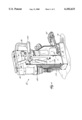
FIG. 1 is a perspective view of a drill press embodying the invention.
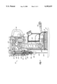
FIG. 2 is a cross-sectional side view of the drill press shown in FIG. 1 and illustrating the spindle in the raised position.
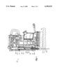
FIG. 3 is a cross-sectional side view similar to that shown in FIG. 2 and illustrating the spindle in the lowered position.
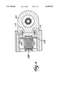
FIG. 4 is a cross-sectional view taken generally along line 4--4 in FIG. 3.
A power tool, such as a drill press 10, embodying the present invention is illustrated in FIG. 1. The drill press 10 generally includes a housing 14 supported by a base 18. The base 18 includes a force applying member (not shown) for connecting the base 18 to the surface of a workpiece W, and an actuating handle 22 for operating the force applying member. In the illustrated construction, the force applying member is a permanent magnet assembly (not shown) for attaching the drill press 10 to a ferro-magnetic workpiece W. In other constructions (not shown), the force applying member may be an electromagnet, a vacuum pad, or a clamp mechanism.
In the illustrated construction, the drill press 10 is a portable drill press, and the housing 14 includes a carrying handle 26 to assist the operator in moving the drill press 10 from workpiece to workpiece. However, it should be understood that the power tool could be a non-portable drill press (not shown) in which the base is supported on the floor of a work area and which includes a support surface for supporting the workpiece.
The drill press 10 includes (see FIG. 2) an electric motor 30 supported by the housing 14 and operable to rotatably drive a telescoping spindle assembly 34 about an axis 38. The motor 30 is powered by a suitable power source (not shown). An on/off lever 42 energizes the motor 30 to drive the spindle assembly 34.
The drill press 10 also includes a drive assembly for connecting the motor 30 to the spindle assembly 34. The drive assembly includes a gear assembly 46 to provide speed reduction of the motor 30. A timing belt 50 connects the gear assembly 46 to the spindle assembly 34. The belt 50 serves as a final drive for the drive assembly and is easily replaceable in case of wear.
The spindle assembly 34 includes a first spindle member 54 supported by roller bearings 58 mounted on the housing 14. The first spindle member 54 is rotatable about the axis 38 but is fixed against movement along the axis 38 relative to the housing 14. The first spindle member 54 includes a drive end 62 engaged by the belt 50. The first spindle member 54 has (see FIG. 3) a hollow inner portion 66, and grooves 70 are defined therein.
The spindle assembly 34 also includes (see FIG. 2) an intermediate spindle member 74 supported by the first spindle member 54. As shown by the change of position between FIGS. 2 and 3, the intermediate spindle member 74 telescopes into and out of the inner portion 66 of the first spindle member 54 along the axis 38. As shown in FIG. 3, splines 78 formed on the outer surface of the intermediate spindle member 74 engage the grooves 70 defined by the first spindle member 54 so that the intermediate spindle member 74 rotates with the first spindle member 54. The intermediate spindle member 74 also has a hollow inner portion 82, and grooves 86 are defined therein.
The spindle assembly 34 also includes (see FIG. 2) a second spindle member 90 supported by the intermediate spindle member 74. As shown by the change of position between FIGS. 2 and 3, the second spindle member 90 telescopes into and out of the inner portion 82 of the intermediate spindle member 74. As shown in FIG. 3, splines 94 formed on the outer surface of the second spindle member 90 engage the grooves 86 defined by the intermediate spindle member 74 so that the second spindle member 90 rotates with the intermediate spindle member 74 and the first spindle member 54.
A tool holder or chuck 98 (see FIG. 2) is supported on the lower end of the second spindle member 90. The chuck 98 supports an output element or drill bit 102 so that the drill bit 102 rotates with the spindle assembly 34. The drill bit 102 moves with the second spindle member 90 along the axis 38 so that the drill bit 102 is movable into engagement with the workpiece W (as shown in FIG. 3) and out of engagement with the workpiece W (as shown in FIGS. 1 and 2).
The drill press 10 also includes (see FIG. 2) a collar 106 supported by the housing 14 for movement along the axis 38. Roller bearings 110 mounted in the collar 106 support the second spindle member 90 so that the second spindle member 90 is rotatable relative to the collar 106. The roller bearings 110 prevent axial movement of the second spindle member 90 relative to the collar 106. The second spindle member 90 is movable with the collar 106 along the axis 38 relative to the housing 14.
As shown in FIG. 4, a pair of tracks 114 are defined by the housing 14 and extend parallel to the axis 38. A portion 118 of the collar 106 extends into each track 114 to guide movement of the collar 106 relative to the housing 14. Engagement of the portions 118 and the tracks 114 prevents movement of the collar 106 and the second spindle member 90 transverse to the axis 38.
As shown in FIG. 3, a flexible sleeve 116 is positioned between the housing 14 and the collar 106 to cover the intermediate spindle member 74 and the second spindle member 90 as these components telescope out of the first spindle member 54. As shown in FIGS. 1 and 2, the flexible sleeve 116 is compressed as the second spindle member 90 and the intermediate spindle member 74 telescope into the first spindle member 58. The flexible sleeve 116 inhibits debris from affecting the operation of the telescoping spindle assembly 34.
The drill press 10 also includes (see FIG. 2) a feed system 122 for moving the spindle assembly 34 between a raised position (shown in FIGS. 1 and 2), in which the drill bit 102 is out of engagement with the workpiece W, and a lowered position (shown in FIG. 3), in which the drill bit 102 is engaged with the workpiece W. As shown in FIG. 2, the feed system 122 is positioned in an opening 126 defined by the housing 14 so that a portion of the feed system 122 is exposed through the opening 126.
The feed system 122 includes a flexible member in the form of an endless loop belt 130 movably supported by a feed mechanism. The belt 130 is connected to the collar 106 so that the second spindle member 90 and the collar 106 are movable with the belt 130. It should be appreciated that the flexible member can comprise other elements, such as a chain, cable, or other suitable element.
The feed mechanism includes first and second sprockets 134 and 138 rotatably supported by the housing 14. The belt 130 engages the first and second sprockets 134 and 138 so that the belt 130 is substantially tensioned between the first and second sprockets 134 and 138. Teeth 142 formed on the first and second sprockets 134 and 138 engage openings 146 formed on the belt 130 so that rotation of the first and second sprockets 134 and 138 causes movement of the belt 130. The feed mechanism also includes (see FIG. 1) a feed handle 150 connected to the first sprocket 134 to rotate the first sprocket 134 and thereby move of the belt 130.
As shown in FIG. 2, a belt retaining assembly connects the belt 130 to the collar 106 and the spindle assembly 34. The belt retaining assembly includes a belt retaining plate 154 removably connected to the collar 106 so that the belt 130 is captured between the collar 106 and the belt retaining plate 154.
A flexible barrier member 158 is positioned to cover the exposed portion of the feed system 122. The lateral edges of the barrier member 158 engage respective recesses 162 formed in the housing 14 so that the barrier member 158 covers the opening 126. The barrier member 158 inhibits debris from entering the opening 126 and affecting the operation of the feed system 122.
With the spindle assembly 34 in the raised position (shown in FIGS. 1 and 2), the barrier member 158 is in an expanded condition. As the spindle assembly 34 is moved to the lowered position (shown in FIG. 3), the collar 106 engages the upper portion of the barrier member 158 and compresses the barrier member 158. As the spindle assembly 34 returns to the raised position (shown in FIGS. 1 and 2), the barrier member 158 returns to the expanded condition. In the illustrated construction, the barrier member 158 has a corrugated configuration to enable the barrier member 158 to compress and expand.
In operation, the drill press 10 is positioned on the surface of the workpiece W. The force applying member in the base 18 is actuated to connect the base 18 to the workpiece W. When the drill press 10 is attached to the workpiece W, the spindle assembly 34 is in the raised position so that the drill bit 102 is out of engagement with the workpiece W.
Once the drill press 10 is attached to the workpiece W, the operator activates the motor 30 to rotatably drive the spindle assembly 34. To engage the drill bit 102 with the workpiece W, the operator then rotates the feed handle 150 in the counterclockwise direction (as shown in FIG. 1), causing the first sprocket 134 to rotate the belt 130. The belt 130 moves the collar 106 in a downward direction (as shown in the change in position between FIG. 2 and FIG. 3), and the intermediate spindle member 74 and the second spindle member 90 telescope out of the first spindle member 54.
Once the operator has finished a desired operation, the feed handle 150 is rotated in the clockwise direction (as shown in FIG. 3), causing the first sprocket 134 to rotate the belt 130. The belt 130 moves the collar 106 in an upward direction (as shown in the change of positions between FIG. 3 and FIG. 2), and the intermediate spindle member 74 and the second spindle member 90 telescope into the first spindle member 58. The spindle assembly 34 is moved to the raised position, and the drill bit 102 is moved out of engagement with the workpiece W.
While a drill press 10 is shown in the illustrated construction, it should be understood that the present invention is applicable to other power tools including a feed system to move an output element relative to the power tool housing and thereby engage an output element with a workpiece.
The foregoing description of the present invention has been presented for purposes of illustration and description. Furthermore, the description is not intended to limit the invention to the form disclosed herein. Consequently, variations and modifications commensurate with the above teachings, and the skill or knowledge of the relative art are within the scope of the present invention. The embodiments described herein are further intended to explain best modes known for practicing the invention and to enable others skilled in the art to utilize the invention in such, or other, embodiments and with various modifications required by the particular applications or uses of the present invention. It is intended that the appended claims be construed to include alternative embodiments to the extent permitted by the prior art.
Claims (17)
1. A power tool comprising:
a base for supporting said power tool on a surface;
a housing supported on said base;
a spindle positioned for movement relative to said housing along an axis and for rotation about said axis, said spindle having an end adapted to support an output element, said spindle being movable along said axis between a lowered position, in which the output element is engageable with a workpiece, and a raised position, in which said output element is out of engagement with the workpiece;
a motor supported by said housing and operable to rotatably drive said spindle; and
a movable flexible member interconnected with said spindle such that said spindle moves with said flexible member.
2. The power tool as set forth in claim 1 and further comprising a collar housing an end of said spindle so that said spindle is rotatable within said collar, said collar being movable relative to said housing and being connected with said flexible member so that movement of said flexible member moves said collar with said spindle.
3. The power tool as set forth in claim 2 and further comprising a retaining member connectable with said flexible member to connect said spindle to said flexible member, said retaining member including a retaining plate removably connected to said collar so that said flexible member is retained between said collar and said retaining plate.
4. The power tool as set forth in claim 2 and further comprising a track extending parallel to said axis, and wherein a portion of said collar extends into said track to prevent movement of said collar relative to said housing in a direction transverse to said axis.
5. The power tool as set forth in claim 1 wherein said flexible member is an endless belt.
6. The power tool as set forth in claim 1 and further comprising a feed mechanism including a sprocket rotatably supported by said housing, said sprocket being engaged with said flexible member such that rotation of said sprocket causes movement of said flexible member.
7. The power tool as set forth in claim 6 wherein said feed mechanism further includes a handle rotatably supported by said housing and connected to said sprocket such that rotation of said handle causes rotation of said sprocket.
8. The power tool as set forth in claim 6 wherein said feed mechanism further includes a second sprocket rotatably supported by said housing and engaged with said flexible member, said second sprocket being spaced from said first-mentioned sprocket such that said flexible member is substantially tensioned between said first-mentioned sprocket and said second sprocket.
9. The power tool as set forth in claim 1 wherein said flexible member comprises an endless loop member.
10. The power tool as set forth in claim 1 wherein said spindle includes
a first spindle member axially fixed relative to said housing, and
a second spindle member supported for axial movement relative to said first spindle member and relative to said housing, said second spindle member being connectable to said flexible member such that said second spindle member telescopes out of said first spindle member to move to the lowered position and such that said second spindle member telescopes into said first spindle member to move to the raised position.
11. A drill press comprising:
a base for supporting said drill press on a surface;
a housing supported on said base, said housing defining an opening;
a spindle positioned for movement relative to said housing along an axis and for rotation about said axis, said spindle having an end adapted to support an output element, said spindle being movable along said axis between a lowered position, in which the output element is engageable with a workpiece, and a raised position, in which said output element is out of engagement with the workpiece;
a motor supported by said housing and operable to rotatably drive said spindle;
a feed system for moving said spindle between the lowered position and the raised position, said feed system being supported by said housing such that a portion of said feed system is exposed through said opening; and
a flexible barrier member supported by said housing to cover said exposed portion of said feed system.
12. The drill press as set forth in claim 11, wherein said barrier member has an expanded condition when said spindle is in the raised position, wherein movement of said spindle from the raised position to the lowered position compresses said barrier member, and wherein subsequent movement of said spindle from the lowered position to the raised position causes said barrier member to return to the expanded condition.
13. The drill press as set forth in claim 11 wherein said barrier member has a corrugated configuration.
14. The drill press as set forth in claim 11 wherein said feed system includes
a sprocket rotatably supported by said housing, and
a flexible member movably engaging said sprocket and connected to said spindle such that rotation of said sprocket moves said spindle between the lowered position and the raised position, wherein said barrier member covers a portion of said flexible member.
15. The drill press as set forth in claim 14 and further comprising:
a collar housing an end of said spindle so that said spindle is rotatable within said collar, said collar being movable relative to said housing; and
a retaining member connectable with said flexible member to connect said spindle to said flexible member, said retaining member including a retaining plate removably connected to said collar so that said flexible member is retained between said collar and said retaining plate so that movement of said feed mechanism moves said collar with said spindle, wherein said barrier member is positioned between said collar and said housing.
16. The drill press as set forth in claim 11 and further comprising a recess extending parallel to said axis, and wherein a portion of said barrier member extends into said recess.
17. A drill press comprising:
a base for supporting said drill press on a surface;
a housing supported on said base, said housing defining an opening;
a spindle positioned for movement relative to said housing along an axis and for rotation about said axis, said spindle including
a first spindle member fixed axially relative to said housing, and
a second spindle member axially movable relative to said first spindle member and relative to said housing, said second spindle member having an end adapted to support an output element, said second spindle member being movable along said axis between a lowered position, in which the output element is engageable with a workpiece, and a raised position, in which said output element is out of engagement with the workpiece;
a motor supported by said housing and operable to rotatably drive said spindle;
a drive system supported by said housing and connected between said motor and said first spindle member;
a feed system for moving said second spindle member between the lowered position and the raised position, said feed system being supported by said housing so that a portion of said feed system is exposed through said opening, said feed system including
a sprocket rotatably supported by said housing,
an endless flexible member movably engaging said sprocket and connected to said spindle such that rotation of said sprocket moves said spindle between the lowered position and the raised position,
a collar housing a portion of said second spindle member so that said second spindle member is rotatable relative to said collar, said collar being movable relative to said housing, and
a retaining member connectable with said flexible member to connect said spindle to said flexible member, said retaining member including a retaining plate removably connected to said collar so that said flexible member is retained between said collar and said retaining plate so that movement of said feed mechanism moves said collar with said second spindle member; and
a flexible barrier member supported by said housing to cover said exposed portion of said feed system, said barrier member having an expanded condition when said spindle is in the raised position, wherein movement of said spindle from the raised position to the lowered position compresses said barrier member, and wherein subsequent movement of said spindle from the lowered position to the raised position causes said barrier member to return to the expanded condition.
Priority Applications (1)
| Application Number | Priority Date | Filing Date | Title |
|---|---|---|---|
| US09/480,277 US6102633A (en) | 1998-04-02 | 2000-01-10 | Feed system for a drill press |
Applications Claiming Priority (2)
| Application Number | Priority Date | Filing Date | Title |
|---|---|---|---|
| US5412098A | 1998-04-02 | 1998-04-02 | |
| US09/480,277 US6102633A (en) | 1998-04-02 | 2000-01-10 | Feed system for a drill press |
Related Parent Applications (1)
| Application Number | Title | Priority Date | Filing Date |
|---|---|---|---|
| US5412098A Continuation | 1998-04-02 | 1998-04-02 |
Publications (1)
| Publication Number | Publication Date |
|---|---|
| US6102633A true US6102633A (en) | 2000-08-15 |
Family
ID=21988922
Family Applications (1)
| Application Number | Title | Priority Date | Filing Date |
|---|---|---|---|
| US09/480,277 Expired - Lifetime US6102633A (en) | 1998-04-02 | 2000-01-10 | Feed system for a drill press |
Country Status (5)
| Country | Link |
|---|---|
| US (1) | US6102633A (en) |
| JP (1) | JP2000052117A (en) |
| DE (1) | DE19915043B4 (en) |
| GB (1) | GB2335871B (en) |
| IT (1) | IT1312242B1 (en) |
Cited By (26)
| Publication number | Priority date | Publication date | Assignee | Title |
|---|---|---|---|---|
| USD439915S1 (en) | 2000-04-06 | 2001-04-03 | Palmgren Industrial Corp. Ltd. | Drill |
| USD447494S1 (en) | 2000-11-08 | 2001-09-04 | Hougen Manufacturing, Inc. | Self-adhering magnetic drill |
| USD470867S1 (en) | 2002-05-31 | 2003-02-25 | Black & Decker Inc. | Magnetic drill press |
| USD470868S1 (en) | 2002-05-31 | 2003-02-25 | Black & Decker Inc. | Magnetic drill press |
| USD472251S1 (en) | 2002-04-30 | 2003-03-25 | Nitto Kohki Co., Ltd. | Drill stand |
| US20040191018A1 (en) * | 2003-03-28 | 2004-09-30 | Nitto Kohki Co., Ltd. | Rotary cutting apparatus |
| US20050025586A1 (en) * | 2003-08-01 | 2005-02-03 | Toshio Mikiya | Electric drill apparatus |
| US20060013663A1 (en) * | 2004-07-02 | 2006-01-19 | Juergen Wiehler | Drilling machine |
| US20060175095A1 (en) * | 2005-02-07 | 2006-08-10 | Tabuchi Co., Ltd. | Boring machine |
| CN1329152C (en) * | 2003-03-28 | 2007-08-01 | 日东工器株式会社 | Rotary cutting apparatus |
| CN100436048C (en) * | 2004-07-16 | 2008-11-26 | 日东工器株式会社 | rotary cutting machine |
| US20090028653A1 (en) * | 2007-07-27 | 2009-01-29 | Wilbert Edward D | Ac/dc magnetic drill press |
| EP2045037A1 (en) * | 2004-07-16 | 2009-04-08 | Nitto Kohki Co., Ltd. | Rotary cutting machine |
| USD681080S1 (en) * | 2012-12-18 | 2013-04-30 | Ting Fong Electric & Machinery Co., Ltd. | Hole drilling machine with magnetic holder |
| US20150027022A1 (en) * | 2013-07-26 | 2015-01-29 | Small Arms Manufacturing Co., Inc. | Machine to manufacture gun barrels and method of using |
| EP2828041A4 (en) * | 2012-03-23 | 2016-04-06 | Claude Ernest Nowland | PORTABLE COLUMN DRILL |
| US9434039B2 (en) | 2012-05-16 | 2016-09-06 | C. & E. Fein Gmbh | Drill press with an adjustable gib |
| US9561568B2 (en) | 2014-04-25 | 2017-02-07 | Black & Decker Inc. | Magnetic drill press with alternate power source |
| US9873156B2 (en) | 2013-11-01 | 2018-01-23 | Milwaukee Electric Tool Corporation | Pilot pin for drill press |
| US10583539B2 (en) | 2012-04-25 | 2020-03-10 | Milwaukee Electric Tool Corporation | Magnetic drill press |
| US20210008677A1 (en) * | 2019-07-12 | 2021-01-14 | C. & E. Fein Gmbh | Magnetic base |
| US20210178571A1 (en) * | 2019-12-12 | 2021-06-17 | C. & E. Fein Gmbh | Magnetic base |
| EP3943226A1 (en) * | 2020-07-20 | 2022-01-26 | C. & E. Fein GmbH | Drilling machine |
| US11279019B2 (en) * | 2019-05-16 | 2022-03-22 | C. & E. Fein Gmbh | Magnetic base |
| US20250041981A1 (en) * | 2022-04-22 | 2025-02-06 | Chiron Group Se | Machine tool with protective bellows |
| DE102024126509A1 (en) * | 2024-09-13 | 2026-03-19 | Itp Gmbh | Device and method for machining a workpiece with a tool |
Families Citing this family (2)
| Publication number | Priority date | Publication date | Assignee | Title |
|---|---|---|---|---|
| DE102010013300A1 (en) * | 2010-03-29 | 2011-09-29 | Daniel Sanwald | Motor-operated press for reshaping food i.e. noodles, in kitchen, has push plate moved into container, container bottom including apertures, and threaded sleeve arranged at push plate and counter shaft |
| US12128485B2 (en) | 2021-11-10 | 2024-10-29 | Hougen Manufacturing, Inc. | Portable electrical drilling assembly with reversibly coupled splined shaft |
Citations (21)
| Publication number | Priority date | Publication date | Assignee | Title |
|---|---|---|---|---|
| US2167153A (en) * | 1936-10-01 | 1939-07-25 | Hirsch Abraham | Electrician's drill |
| US2385712A (en) * | 1944-03-06 | 1945-09-25 | Jess Cohen | Machine for cutting skins |
| US2550012A (en) * | 1949-04-15 | 1951-04-24 | Krafka Stefan | Drill press speed reducing assembly |
| US2578995A (en) * | 1948-06-05 | 1951-12-18 | Melvin H Emrick | Tapping machine |
| US2647407A (en) * | 1950-10-07 | 1953-08-04 | Leland Gifford Co | Machine tool spindle construction |
| US2651975A (en) * | 1949-05-11 | 1953-09-15 | Soloff Milton | Internal carving machine |
| US2664756A (en) * | 1952-03-07 | 1954-01-05 | William L Fismer | Drill press |
| US2669135A (en) * | 1953-05-13 | 1954-02-16 | Jack K Moore | Machine tool construction |
| US2814216A (en) * | 1953-12-28 | 1957-11-26 | J & F Mfg Company | Multiple spindle machine for drilling, tapping and similar operations |
| US3131584A (en) * | 1961-05-01 | 1964-05-05 | Giddings & Lewis | Horizontal boring machine |
| US3158044A (en) * | 1961-04-24 | 1964-11-24 | Northrop Corp | Precision maching apparatus |
| US3314312A (en) * | 1964-07-07 | 1967-04-18 | Rockwell Mfg Co | Variable speed power feed mechanism for drill presses and like power tools |
| US3803927A (en) * | 1972-07-10 | 1974-04-16 | Bridgeport Machines | Coaxial force and movement mechanism for a machine tool |
| US3894809A (en) * | 1973-07-16 | 1975-07-15 | Hollins J R | Drill press arrangement |
| GB1574343A (en) * | 1978-05-26 | 1980-09-03 | Smit & Sons Diamond Tools | Hydraulic drive arrangement |
| US4507030A (en) * | 1982-07-26 | 1985-03-26 | Bourn & Koch Machine Tool Company | Cam operated machining unit |
| US4573834A (en) * | 1984-12-31 | 1986-03-04 | Kabushiki Kaisha Kawakami Seisakusho | Piercer |
| US4622022A (en) * | 1983-06-20 | 1986-11-11 | Neapco, Inc. | Telescoping tubes for torque transmission |
| US4945745A (en) * | 1988-03-11 | 1990-08-07 | Davy Mckee (Sheffield) Limited | Telescopic drive spindle assembly |
| US5354159A (en) * | 1993-12-09 | 1994-10-11 | Excellon Automation | Cable drive for drilling machine Z-axis |
| US5517746A (en) * | 1994-09-08 | 1996-05-21 | Emerson Electric Co. | Variable speed direct drive drill press/router |
Family Cites Families (1)
| Publication number | Priority date | Publication date | Assignee | Title |
|---|---|---|---|---|
| US2891426A (en) * | 1958-10-23 | 1959-06-23 | Ralph W Walsh | Method of metal drilling |
-
1999
- 1999-04-01 DE DE19915043A patent/DE19915043B4/en not_active Expired - Fee Related
- 1999-04-01 GB GB9907497A patent/GB2335871B/en not_active Expired - Fee Related
- 1999-04-02 JP JP11131784A patent/JP2000052117A/en active Pending
- 1999-04-02 IT IT1999MI000703A patent/IT1312242B1/en active
-
2000
- 2000-01-10 US US09/480,277 patent/US6102633A/en not_active Expired - Lifetime
Patent Citations (21)
| Publication number | Priority date | Publication date | Assignee | Title |
|---|---|---|---|---|
| US2167153A (en) * | 1936-10-01 | 1939-07-25 | Hirsch Abraham | Electrician's drill |
| US2385712A (en) * | 1944-03-06 | 1945-09-25 | Jess Cohen | Machine for cutting skins |
| US2578995A (en) * | 1948-06-05 | 1951-12-18 | Melvin H Emrick | Tapping machine |
| US2550012A (en) * | 1949-04-15 | 1951-04-24 | Krafka Stefan | Drill press speed reducing assembly |
| US2651975A (en) * | 1949-05-11 | 1953-09-15 | Soloff Milton | Internal carving machine |
| US2647407A (en) * | 1950-10-07 | 1953-08-04 | Leland Gifford Co | Machine tool spindle construction |
| US2664756A (en) * | 1952-03-07 | 1954-01-05 | William L Fismer | Drill press |
| US2669135A (en) * | 1953-05-13 | 1954-02-16 | Jack K Moore | Machine tool construction |
| US2814216A (en) * | 1953-12-28 | 1957-11-26 | J & F Mfg Company | Multiple spindle machine for drilling, tapping and similar operations |
| US3158044A (en) * | 1961-04-24 | 1964-11-24 | Northrop Corp | Precision maching apparatus |
| US3131584A (en) * | 1961-05-01 | 1964-05-05 | Giddings & Lewis | Horizontal boring machine |
| US3314312A (en) * | 1964-07-07 | 1967-04-18 | Rockwell Mfg Co | Variable speed power feed mechanism for drill presses and like power tools |
| US3803927A (en) * | 1972-07-10 | 1974-04-16 | Bridgeport Machines | Coaxial force and movement mechanism for a machine tool |
| US3894809A (en) * | 1973-07-16 | 1975-07-15 | Hollins J R | Drill press arrangement |
| GB1574343A (en) * | 1978-05-26 | 1980-09-03 | Smit & Sons Diamond Tools | Hydraulic drive arrangement |
| US4507030A (en) * | 1982-07-26 | 1985-03-26 | Bourn & Koch Machine Tool Company | Cam operated machining unit |
| US4622022A (en) * | 1983-06-20 | 1986-11-11 | Neapco, Inc. | Telescoping tubes for torque transmission |
| US4573834A (en) * | 1984-12-31 | 1986-03-04 | Kabushiki Kaisha Kawakami Seisakusho | Piercer |
| US4945745A (en) * | 1988-03-11 | 1990-08-07 | Davy Mckee (Sheffield) Limited | Telescopic drive spindle assembly |
| US5354159A (en) * | 1993-12-09 | 1994-10-11 | Excellon Automation | Cable drive for drilling machine Z-axis |
| US5517746A (en) * | 1994-09-08 | 1996-05-21 | Emerson Electric Co. | Variable speed direct drive drill press/router |
Non-Patent Citations (10)
| Title |
|---|
| Black & Decker Industry & Construction s Instruction Manual for 1555, 1556 and 1557 Magnetic Drill Presses, published before Apr. 2, 1997. * |
| Black & Decker Industry & Construction's Instruction Manual for 1555, 1556 and 1557 Magnetic Drill Presses, published before Apr. 2, 1997. |
| Fein 270 14/KBM 558 6 3 Operating Instructions (In English) by C. & E. Fein GmbH & Co., Stuttgart, Deutschland, published before Apr. 2, 1997. * |
| Fein 270 14/KBM 558-6-3 Operating Instructions (In English) by C. & E. Fein GmbH & Co., Stuttgart, Deutschland, published before Apr. 2, 1997. |
| Hougen Rotabroach Portable Magnetic Drills Operator s Manual Model 10904, published before Aprr. 2, 1997. * |
| Hougen Rotabroach Portable Magnetic Drills Operator's Manual Model 10904, published before Aprr. 2, 1997. |
| Milwaukee Electric Tool Corporation s Operator s Manual for Heavy Duty 4245 Steel Hawg Permanent Magnet Metal Boring System, published before Apr. 2, 1997. * |
| Milwaukee Electric Tool Corporation's Operator's Manual for Heavy-Duty 4245 Steel Hawg Permanent Magnet Metal Boring System, published before Apr. 2, 1997. |
| USA 5000 Slugger Portable Magnetic Drilling Machine by Jancy Engineering Company Operator s Manual Model 18066 or 18080, published before Apr. 2, 1997. * |
| USA 5000 Slugger Portable Magnetic Drilling Machine by Jancy Engineering Company Operator's Manual Model #18066 or #18080, published before Apr. 2, 1997. |
Cited By (39)
| Publication number | Priority date | Publication date | Assignee | Title |
|---|---|---|---|---|
| USD439915S1 (en) | 2000-04-06 | 2001-04-03 | Palmgren Industrial Corp. Ltd. | Drill |
| USD447494S1 (en) | 2000-11-08 | 2001-09-04 | Hougen Manufacturing, Inc. | Self-adhering magnetic drill |
| USD472251S1 (en) | 2002-04-30 | 2003-03-25 | Nitto Kohki Co., Ltd. | Drill stand |
| USD470867S1 (en) | 2002-05-31 | 2003-02-25 | Black & Decker Inc. | Magnetic drill press |
| USD470868S1 (en) | 2002-05-31 | 2003-02-25 | Black & Decker Inc. | Magnetic drill press |
| CN1329152C (en) * | 2003-03-28 | 2007-08-01 | 日东工器株式会社 | Rotary cutting apparatus |
| US7001117B2 (en) * | 2003-03-28 | 2006-02-21 | Nitto Kohki Co., Ltd. | Rotary cutting apparatus |
| US20040191018A1 (en) * | 2003-03-28 | 2004-09-30 | Nitto Kohki Co., Ltd. | Rotary cutting apparatus |
| US20050025586A1 (en) * | 2003-08-01 | 2005-02-03 | Toshio Mikiya | Electric drill apparatus |
| US20060013663A1 (en) * | 2004-07-02 | 2006-01-19 | Juergen Wiehler | Drilling machine |
| US7520702B2 (en) * | 2004-07-02 | 2009-04-21 | C. & E. Fein Gmbh | Drilling machine |
| US20090129880A1 (en) * | 2004-07-16 | 2009-05-21 | Nitto Kohki Co., Ltd. | Rotary cutting machine |
| CN100436048C (en) * | 2004-07-16 | 2008-11-26 | 日东工器株式会社 | rotary cutting machine |
| US7862267B2 (en) | 2004-07-16 | 2011-01-04 | Nitto Kohki Co., Ltd. | Rotary cutting machine |
| EP2045037A1 (en) * | 2004-07-16 | 2009-04-08 | Nitto Kohki Co., Ltd. | Rotary cutting machine |
| US20060175095A1 (en) * | 2005-02-07 | 2006-08-10 | Tabuchi Co., Ltd. | Boring machine |
| US20090028653A1 (en) * | 2007-07-27 | 2009-01-29 | Wilbert Edward D | Ac/dc magnetic drill press |
| US8376667B2 (en) * | 2007-07-27 | 2013-02-19 | Milwaukee Electric Tool Corporation | AC/DC magnetic drill press |
| EP2828041A4 (en) * | 2012-03-23 | 2016-04-06 | Claude Ernest Nowland | PORTABLE COLUMN DRILL |
| US10583539B2 (en) | 2012-04-25 | 2020-03-10 | Milwaukee Electric Tool Corporation | Magnetic drill press |
| US9434039B2 (en) | 2012-05-16 | 2016-09-06 | C. & E. Fein Gmbh | Drill press with an adjustable gib |
| USD681080S1 (en) * | 2012-12-18 | 2013-04-30 | Ting Fong Electric & Machinery Co., Ltd. | Hole drilling machine with magnetic holder |
| US20150027022A1 (en) * | 2013-07-26 | 2015-01-29 | Small Arms Manufacturing Co., Inc. | Machine to manufacture gun barrels and method of using |
| US9346111B2 (en) * | 2013-07-26 | 2016-05-24 | E.R. Shaw Inc. | Machine to manufacture gun barrels and method of using |
| US9873156B2 (en) | 2013-11-01 | 2018-01-23 | Milwaukee Electric Tool Corporation | Pilot pin for drill press |
| US10183344B2 (en) | 2013-11-01 | 2019-01-22 | Milwaukee Electric Tool Corporation | Pilot pin for drill press |
| US11110522B2 (en) | 2013-11-01 | 2021-09-07 | Milwaukee Electric Tool Corporation | Pilot pin for drill press |
| US9561568B2 (en) | 2014-04-25 | 2017-02-07 | Black & Decker Inc. | Magnetic drill press with alternate power source |
| US10118265B2 (en) | 2014-04-25 | 2018-11-06 | Black & Decker, Inc. | Magnetic drill press with alternate power source |
| US10369670B2 (en) | 2014-04-25 | 2019-08-06 | Black & Decker, Inc. | Magnetic drill press with alternate power source |
| US11279019B2 (en) * | 2019-05-16 | 2022-03-22 | C. & E. Fein Gmbh | Magnetic base |
| US20210008677A1 (en) * | 2019-07-12 | 2021-01-14 | C. & E. Fein Gmbh | Magnetic base |
| US12030153B2 (en) * | 2019-07-12 | 2024-07-09 | C. & E. Fein Gmbh | Magnetic base |
| US20210178571A1 (en) * | 2019-12-12 | 2021-06-17 | C. & E. Fein Gmbh | Magnetic base |
| US11980949B2 (en) | 2020-07-20 | 2024-05-14 | C.&E. Fein GmbH | Drilling machine |
| EP3943226A1 (en) * | 2020-07-20 | 2022-01-26 | C. & E. Fein GmbH | Drilling machine |
| US20250041981A1 (en) * | 2022-04-22 | 2025-02-06 | Chiron Group Se | Machine tool with protective bellows |
| US12521828B2 (en) * | 2022-04-22 | 2026-01-13 | Chiron Group Se | Machine tool with protective bellows |
| DE102024126509A1 (en) * | 2024-09-13 | 2026-03-19 | Itp Gmbh | Device and method for machining a workpiece with a tool |
Also Published As
| Publication number | Publication date |
|---|---|
| DE19915043A1 (en) | 1999-10-07 |
| ITMI990703A1 (en) | 2000-10-02 |
| IT1312242B1 (en) | 2002-04-09 |
| DE19915043B4 (en) | 2008-08-21 |
| JP2000052117A (en) | 2000-02-22 |
| GB9907497D0 (en) | 1999-05-26 |
| GB2335871A (en) | 1999-10-06 |
| GB2335871B (en) | 2003-02-26 |
Similar Documents
| Publication | Publication Date | Title |
|---|---|---|
| US6102633A (en) | Feed system for a drill press | |
| US4313478A (en) | Wood working router | |
| US4158315A (en) | Track guided carriage unit | |
| EP0860250A3 (en) | Bevel locking system for a sliding compound miter saw | |
| US4134459A (en) | Rotary cutting equipment | |
| JP2005520696A (en) | Orbital hand tool device for drilling | |
| AU6886900A (en) | Hand tool apparatus for orbital drilling | |
| CA2280566A1 (en) | Portable journal turning lathe | |
| CA2144804A1 (en) | Variable Speed Direct Drive Drill Press/Router | |
| US5752905A (en) | Automatic tool-changing mechanism | |
| JPH09117837A (en) | Electric blowing/drilling machine | |
| JP4489865B2 (en) | Press-type drilling handling device | |
| GB2378145A (en) | Feed system for a drill press | |
| EP0940232A3 (en) | Dog clutch mechanism for a chain saw | |
| JP3491054B2 (en) | Cutting device with rotating head | |
| WO2006043170A3 (en) | A machining head for machine tools with a shaft with low thermal expansion coefficient | |
| EP1099518A3 (en) | Low profile magnetic base drill | |
| JPH0810506Y2 (en) | Turntable fixing device for machine tools | |
| EP0556226B1 (en) | Improvements in or relating to machine tools | |
| JPH06315809A (en) | Boring machine | |
| SU1751630A1 (en) | Arrangement for making slots in ice | |
| JPS6029395Y2 (en) | Stopper switching device | |
| CA2199071A1 (en) | Orbital lathe | |
| EP1186374A3 (en) | Machine tool with device for driving a spindle mounting slide | |
| SU1209375A1 (en) | Radial-drilling machine |
Legal Events
| Date | Code | Title | Description |
|---|---|---|---|
| STCF | Information on status: patent grant |
Free format text: PATENTED CASE |
|
| FEPP | Fee payment procedure |
Free format text: PAYOR NUMBER ASSIGNED (ORIGINAL EVENT CODE: ASPN); ENTITY STATUS OF PATENT OWNER: LARGE ENTITY |
|
| FPAY | Fee payment |
Year of fee payment: 4 |
|
| FPAY | Fee payment |
Year of fee payment: 8 |
|
| REMI | Maintenance fee reminder mailed | ||
| FPAY | Fee payment |
Year of fee payment: 12 |