US6102547A - Illumination device - Google Patents
Illumination device Download PDFInfo
- Publication number
- US6102547A US6102547A US09/127,342 US12734298A US6102547A US 6102547 A US6102547 A US 6102547A US 12734298 A US12734298 A US 12734298A US 6102547 A US6102547 A US 6102547A
- Authority
- US
- United States
- Prior art keywords
- reflector
- light
- flashlight
- emitting tube
- cross
- Prior art date
- Legal status (The legal status is an assumption and is not a legal conclusion. Google has not performed a legal analysis and makes no representation as to the accuracy of the status listed.)
- Expired - Lifetime
Links
Images


Classifications
-
- G—PHYSICS
- G03—PHOTOGRAPHY; CINEMATOGRAPHY; ANALOGOUS TECHNIQUES USING WAVES OTHER THAN OPTICAL WAVES; ELECTROGRAPHY; HOLOGRAPHY
- G03B—APPARATUS OR ARRANGEMENTS FOR TAKING PHOTOGRAPHS OR FOR PROJECTING OR VIEWING THEM; APPARATUS OR ARRANGEMENTS EMPLOYING ANALOGOUS TECHNIQUES USING WAVES OTHER THAN OPTICAL WAVES; ACCESSORIES THEREFOR
- G03B15/00—Special procedures for taking photographs; Apparatus therefor
- G03B15/02—Illuminating scene
- G03B15/03—Combinations of cameras with lighting apparatus; Flash units
- G03B15/05—Combinations of cameras with electronic flash apparatus; Electronic flash units
-
- G—PHYSICS
- G03—PHOTOGRAPHY; CINEMATOGRAPHY; ANALOGOUS TECHNIQUES USING WAVES OTHER THAN OPTICAL WAVES; ELECTROGRAPHY; HOLOGRAPHY
- G03B—APPARATUS OR ARRANGEMENTS FOR TAKING PHOTOGRAPHS OR FOR PROJECTING OR VIEWING THEM; APPARATUS OR ARRANGEMENTS EMPLOYING ANALOGOUS TECHNIQUES USING WAVES OTHER THAN OPTICAL WAVES; ACCESSORIES THEREFOR
- G03B2215/00—Special procedures for taking photographs; Apparatus therefor
- G03B2215/05—Combinations of cameras with electronic flash units
- G03B2215/0503—Built-in units
- G03B2215/0507—Pop-up mechanisms
-
- G—PHYSICS
- G03—PHOTOGRAPHY; CINEMATOGRAPHY; ANALOGOUS TECHNIQUES USING WAVES OTHER THAN OPTICAL WAVES; ELECTROGRAPHY; HOLOGRAPHY
- G03B—APPARATUS OR ARRANGEMENTS FOR TAKING PHOTOGRAPHS OR FOR PROJECTING OR VIEWING THEM; APPARATUS OR ARRANGEMENTS EMPLOYING ANALOGOUS TECHNIQUES USING WAVES OTHER THAN OPTICAL WAVES; ACCESSORIES THEREFOR
- G03B2215/00—Special procedures for taking photographs; Apparatus therefor
- G03B2215/05—Combinations of cameras with electronic flash units
- G03B2215/0514—Separate unit
- G03B2215/0517—Housing
- G03B2215/0525—Reflector
Definitions
- the present invention relates to an illumination device and, more particularly, to the shape of a reflector used in a flashlight-emitting device for a camera or the like.
- FIGS. 24 to 32 are views for explaining a conventional flashlight-emitting device for a camera, in which FIG. 24 is a perspective view showing the appearance of a flashlight-emitting device for a camera, FIG. 25 is a cross-sectional view showing the flashlight-emitting device in a direction perpendicular to the axis of a light-emitting tube, FIG. 26 is an upper view of a reflector 2, and FIG. 27 is a front view of an opening portion of the reflector 2.
- a flashlight-emitting device for a camera is generally constituted by a flashlight discharge tube 1 in which a xenon (Xe) gas or the like is sealed, and a reflector 2 for reflecting light from the flashlight discharge tube 1 in the forward direction.
- the cross-section perpendicular to the axis direction of the flashlight discharge tube 1, as shown in FIG. 25, is formed to have an elliptical shape or an almost quadratic-curve shape.
- the side-surface portions of the reflector 2 are constituted by flat plates. As is also apparent from the upper view in FIG. 26, the side-surface portions diverge at a predetermined angle toward the opening portion.
- FIGS. 28 to 32 are views for explaining the problems of the conventional flashlight-emitting device for a camera.
- FIG. 28 shows a state wherein the shape of an opening portion is changed with respect to the shape of the opening portion of the camera body
- FIGS. 29 and 30 show cross-sectional views of the central portion in FIG. 28.
- FIG. 29 shows a state wherein the opening portion of the reflector 2 is partially cut away
- FIG. 30 shows a state wherein the opening portion of the reflector 2 is partially masked.
- the outer peripheral portion of the reflector 2 is partially cut away as shown in FIG. 29 to make the size of the opening portion of the reflector 2 equal to the size of the opening portion of the camera body, or a predetermined portion of the reflector 2 is covered with a mask 3 to make the sizes of the opening portions equal to each other as shown in FIG. 30. For this reason, loss of light irradiated on the object is large.
- the opening portion of the reflector is formed to have a predetermined shape for design, loss of light rays occurs depending on the shape of the opening portion.
- An illumination device having a light-emitting tube and a reflector for reflecting rays of light irradiated from the light-emitting tube has the following characteristic feature.
- the shape of at least one section arranged on the reflector and viewed perpendicular to the axis direction of the light-emitting tube is different from the shapes of the other sections along the axis direction of the light-emitting tube.
- FIG. 1 is a perspective view showing the appearance of a flashlight-emitting device for a camera according to a first embodiment of the present invention.
- FIG. 2 is an upper view showing the flashlight-emitting device for a camera according to the first embodiment.
- FIG. 3 is a front view showing the flashlight-emitting device for a camera according to the first embodiment when viewed from an opening portion side.
- FIG. 4 is a cross-sectional view showing the central section of the flashlight-emitting device for a camera according to the first embodiment.
- FIG. 5 is a cross-sectional view showing a section of the flashlight-emitting device for a camera according to the first embodiment to one side with respect to the center of the device.
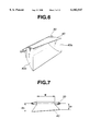
- FIG. 6 is a perspective view showing the appearance of a flashlight-emitting device for a camera according to a second embodiment of the present invention.
- FIG. 7 is an upper view showing the flashlight-emitting device for a camera according to the second embodiment.
- FIG. 8 is a front view showing the flashlight-emitting device for a camera according to the second embodiment when viewed from an opening portion side.
- FIG. 9 is a cross-sectional view showing the central section of the flashlight-emitting device for a camera according to the second embodiment.
- FIG. 10 is a cross-sectional view showing a section of the flashlight-emitting device for a camera according to the second embodiment to one side with respect to the center of the device.
- FIG. 11 is a front view showing a flashlight-emitting device according to a third embodiment of the present invention when viewed from the opening portion side.
- FIG. 12 is a side view showing the flashlight-emitting device for a camera according to the third embodiment.
- FIG. 13 is a front view showing a flashlight-emitting device according to a fourth embodiment of the present invention when viewed from the opening portion side.
- FIG. 14 is a side view showing the flashlight-emitting device for a camera according to the fourth embodiment.
- FIG. 15 is a front view showing a flashlight-emitting device according to a fifth embodiment of the present invention when viewed from the opening portion side.
- FIG. 16 is a side view showing the flashlight-emitting device for a camera according to the fifth embodiment.
- FIG. 17 is a front view showing a flashlight-emitting device according to a sixth embodiment of the present invention when viewed from the opening portion side.
- FIG. 18 is a side view showing the flashlight-emitting device for a camera according to the sixth embodiment.
- FIG. 19 is a front view showing a flashlight-emitting device according to a seventh embodiment of the present invention when viewed from the opening portion side.
- FIG. 20 is a side view showing the flashlight-emitting device for a camera according to the seventh embodiment.
- FIG. 21 is a front view showing a flashlight-emitting device according to an eighth embodiment of the present invention when viewed from the opening portion side.
- FIG. 22 is side view showing the flashlight-emitting device for a camera according to the eight embodiment.
- FIG. 23 is a view showing a state wherein a reflector used in the flashlight-emitting device for a camera according to the seventh embodiment is built in a flash unit.
- FIG. 24 is a perspective view showing the appearance of a conventional flashlight-emitting device for a camera to explain the flashlight-emitting device.
- FIG. 25 is a cross-sectional view showing the conventional flashlight-emitting device at an arbitrary position.
- FIG. 26 is an upper view showing the conventional flashlight-emitting device for a camera.
- FIG. 27 is a front view showing the conventional flashlight-emitting device when viewed from an opening portion side.
- FIG. 28 is a view for explaining a state wherein the shape of the opening portion of the conventional flashlight-emitting device is changed with respect to the opening portion of the camera.
- FIG. 29 is a cross-sectional view for explaining a problem occurring when the opening portion of the conventional flashlight-emitting device is partially cut away.
- FIG. 30 is a cross-sectional view for explaining a problem occurring when the opening portion of the conventional flashlight-emitting device is partially masked.
- FIG. 31 is a view showing the appearance of a conventional camera having a flash unit.
- FIG. 32 is a view for explaining a vignetting portion in a state wherein the flash unit in the conventional camera is in use.
- FIGS. 1 to 4 are views for explaining a first embodiment of the present invention, and show a flashlight-emitting device arranged in a camera as an illumination device.
- FIG. 1 is a perspective view showing the appearance of a flashlight-emitting device used in a camera
- FIG. 2 is an upper view showing the flashlight-emitting device
- FIG. 3 is a front view showing the shape of the opening portion of the flashlight-emitting device.
- FIGS. 4 and 5 are cross-sectional views showing the flashlight-emitting device at the two positions indicated in FIG. 3.
- the flashlight-emitting device is constituted by a cylindrical flashlight discharge tube 10 and a reflector 20 consisting of an aluminum thin plate having an inner surface serving as a reflecting surface.
- the cross-sectional shape of the reflector 20 is elliptical in shape which is a conical curve.
- side reflecting plates 20a and 20b are formed such that the side reflecting plates 20a and 20b diverge from the end portions of an effective light-emitting region E of the flashlight discharge tube 10 toward the opening portion.
- the side reflecting plates 20a and 20b are formed such that a depth D, which is the distance from the flashlight discharge tube 10 to the opening portion, is set to be a predetermined value.
- the shape of the front opening portion is formed such that a opening width W perpendicular to the axis direction of the flashlight discharge tube 10 gradually changes from the substantially central portion of the flashlight discharge tube 10 (see FIG. 4) to the left and right sides within a range from Wi to W1.
- FIGS. 4 and 5 show two cross-sections perpendicular to the longitudinal axis direction of the flashlight discharge tube 10 within the effective light-emitting region E of the flashlight discharge tube 10 shown in FIG. 3.
- the cross-sectional shape shown in FIG. 5 is an elliptical shape having an opening width Wn.
- the cross-sectional shape of the substantially central portion shown in FIG. 4 is an elliptical shape having an opening width Wi.
- the first focal point positions of these ellipses coincide with each other.
- the axial center of the flashlight discharge tube 10 is located at the first focal point of each elliptical cross-sectional shape.
- substantially all the rays of light emitted from the flashlight discharge tube 10 are reflected by the reflector 20 at an angle, for example, of ⁇ i or ⁇ n in the examples above, and then reflected within the range passing through the second focal point of the elliptical shape having the opening width Wi or Wn in the examples above.
- the sizes of the cross-sections perpendicular to the longitudinal axis direction of the flashlight discharge tube 10 are made different from each other with respect to the cross-section of the substantially central portion of the flashlight discharge tube 10, and light reflected by each of the cross sections passes through the focal point position of the corresponding ellipse, so that the reflection efficiency is not degraded. Therefore, when the exposure area of the opening portion of the camera body in which the reflector is set is not equal to the size of the opening portion of the reflector, or when the shape of the opening portion of the reflector must be changed for design purposes, if the opening portion of the reflector has a varying opening width W, a reflector which prevents loss of flashlight rays can be manufactured.
- the cross-sectional shape of the reflector 20 is formed as an elliptical shape which is a conical curve
- the sectional shape may be constituted by another conical curve such as a parabolic curve or a hyperbolic curve.
- the cross-sectional shape need not be constituted by a perfectly conical curve, and the elliptical shape may be constituted by an approximate curve to a hyperbolic curve or a parabolic curve, a matter of course.
- the second embodiment illustrates a flashlight-emitting device used in a camera as an illumination device as in the first embodiment.
- FIG. 6 is a perspective view showing the arrangement of a flashlight-emitting device according to the second embodiment
- FIG. 7 is an upper view showing the flashlight-emitting device.
- FIG. 8 is a front view for explaining the shape of the opening portion of the flashlight-emitting device
- FIGS. 9 and 10 are cross-sectional views showing the cross sections of the reflector shown in FIG. 8.
- the shape in the second embodiment is obtained by cutting the reflector 20 described in the first embodiment of FIG. 3 at the center. More specifically, as shown in FIG. 6, the side reflecting plates 40a and 40b formed on reflector 40 are planar . As in the first embodiment, the planar sides diverge from the end portions of an effective light-emitting region E' of a flashlight discharge tube 30 to the opening portion as shown in FIG. 7. However, the second embodiment is different from the first embodiment in the following points. That is, the planar plates are formed such that a depth D gradually increases from D1 to Dn along the axis of the flashlight discharge tube 30, and, as shown in FIG. 8, an opening width W of the front opening portion linearly changes from W1 to Wi in corresponding fashion.
- FIGS. 9 and 10 show two cross-sections perpendicular to the longitudinal axis direction of the flashlight discharge tube 30 within the effective light-emitting region E' of the flashlight discharge tube 30.
- the cross-sectional shapes shown in FIGS. 9 and 10 are elliptical having an opening width Wn' and a depth Dn', and an opening with Wn" and a depth Dn", respectively.
- the axial center of the flashlight discharge tube 30 is located along the first focal point positions of these ellipses.
- substantially all the rays of light emitted from the flashlight discharge tube 30 are reflected by the reflector 40 at an angle of 0n' or 0n" and then reflected within the range passing through the second focal points of the ellipses.
- the shapes and/or sizes of the cross-sections perpendicular to the axis direction of the flashlight discharge tube 30 are made different from each other so that the reflection efficiency is not degraded. Therefore, when the exposure area of the opening portion of the camera body in which the reflector is set is not equal to the size of the opening portion of the reflector, or when the shape of the opening portion of the reflector must be changed for design purposes, if the opening portion of the reflector has a varying opening width W, a reflector which prevents loss of flashlight rays can be manufactured.
- the cross-sectional shape of the reflector is elliptical
- the cross-sectional shape may be constituted by another conical curve such as a parabolic curve or a hyperbolic curve or an approximate curve to these curves.
- the first and second embodiments are constituted such that the different cross-sections perpendicular to the longitudinal axis direction of a light-emitting tube form a continuous profile when viewed from the front opening portion.
- the third embodiment is different from the first and second embodiments in that a reflector 50 has one discontinuous section. More specifically, as shown in FIG. 11, the reflector 50 is formed by coupling a first reflector 50a constituted by successive cross-sections each having a height H to a second reflector 50b constituted by successive cross-sections each having a height h smaller than the height of the first reflector 50a. A coupling region K between the first reflector 50a and the second reflector 50b forms a section having a discontinuous profile.
- FIG. 12 is a right-side view of FIG. 11.
- the third embodiment even if the height of the opening portion of the camera body in which the reflector is set changes at the coupling region K for schematic or design convenience purposes, when the shape of the reflector is changed in accordance with the height of the camera body opening portion, a reflector which prevents loss of flashlight rays can be manufactured.
- the first and second embodiments are constituted such that the different cross-sections perpendicular to the longitudinal axis direction of the light-emitting tube are continuous in profile when viewed from the front opening portion.
- the fourth embodiment is different from the first and second embodiments in that a reflector 60 is constituted by a first reflector 60a having successive but differently sized cross-sections and a second reflector 60b having successive equally sized cross-sections. More specifically, as shown in FIG. 13, the shape of the reflector 60 is constituted by coupling the first reflector 60a and the second reflector 60b to each other at a coupling region K having a discontinuous profile.
- FIG. 14 is a right-side view of FIG. 13.
- the reflector is constituted by combining the section having varying cross sections and the section having uniform cross-sections together. For this reason, the reflector can cope with a case wherein the shape of the opening portion of the camera body in which the reflector is set changes for schematic or design convenience purposes without loss of flashlight rays.
- the fourth embodiment is constituted such that the reflector 60 is constituted by a portion having different successive cross-sections and a portion having the same successive cross-sections.
- a reflector according to the fifth embodiment is constituted by a further combination of these portions. More specifically, as shown in FIG. 15 and FIG. 16 obtained by viewing FIG. 15 from the right, first and third reflectors 70a and 70c having different successive cross-sections are arranged on both sides of a second reflector 70b having the same successive cross-sections, and coupling regions K1 and K2 between the reflectors 70a and 70c and the reflector 70b have discontinuous profiles. Therefore, according to the fifth embodiment, the same effect as provided by the fourth embodiment can be obtained.
- the portion having different successive cross-sections is formed on the upper side of the center axis of the light-emitting tube, and the portion having the same successive cross-sections is formed on the lower side of the center axis of the light-emitting tube. Therefore, according to the sixth embodiment, in addition to the effect of the fourth embodiment, the same effect can be specially obtained when the upper side of the center axis of the light-emitting tube is restricted.
- a seventh embodiment of the present invention will be described below with reference to FIGS. 19 and 20.
- a reflector according to the seventh embodiment is obtained by improving the sectional portion having the different successive cross-sections formed on the upper side of the center axis of the light-emitting tube of the sixth embodiment.
- the reflector 90 as shown in FIG. 19 and in the side view of FIG. 20 obtained by viewing FIG. 19 from the right, a sectional portion 90a having different successive cross-sections and a portion 90b having the same successive cross-sections are formed on the upper side of the center axis of a light-emitting tube. Therefore, the same effect as in the sixth embodiment can be obtained.
- FIG. 21 is a front view of the eighth embodiment.
- the outside profile lines on both sides of the center axis of the light-emitting tube are constituted by conical curves such as elliptical curves or parabolic curves, and the outside profile lines are symmetrical with respect to a center line T passing through the center of the light-emitting tube.
- the shape of a cross-section perpendicular to the center line of the light-emitting tube is also constituted by a conical curve such as an elliptical curve or a parabolic curve.
- FIG. 22 is a right-side view of FIG. 21.
- the reflectors having a discontinuous profiles at regions K between different sectional portions have been described in the third to eighth embodiments. An example wherein one of these reflectors is actually incorporated into a camera will be described below.
- FIG. 23 shows an example wherein the reflector of the seventh embodiment (see FIG. 19 and FIG. 20) is built in a flash unit (see FIG. 31 and FIG. 32) arranged on a conventional camera.
- a "vignetting portion" see FIG. 32
- the portion corresponding to the "vignetting portion” is cut away to obtain a light-irradiating reflector having the shape (see the double-chain line) shown in FIG. 19. In this manner, the amount of irradiated light is prevented from being reduced, and high efficiency light distribution can be realized as a whole.
- an optical member such as a Fresnel lens may be arranged on the front surface of the reflector, as a matter of course.
- an illumination device which is free from the loss of light rays commonly experienced with conventional illumination devices when the exposure area of the opening portion of a camera body in which a reflector is set is not equal to the size of the opening portion of the reflector.
- the illumination device of the present invention light rays which were previously lost can now be effectively used. Since the design of the camera is regarded as the most important consideration, even if the shape of the front opening portion of the reflector is different from the shape of the opening portion of the camera, the present inventions provides an illumination device having a highly efficient convergence of light.
Landscapes
- Physics & Mathematics (AREA)
- General Physics & Mathematics (AREA)
- Stroboscope Apparatuses (AREA)
Abstract
Description
Claims (26)
Applications Claiming Priority (2)
| Application Number | Priority Date | Filing Date | Title |
|---|---|---|---|
| JP9-207446 | 1997-08-01 | ||
| JP20744697 | 1997-08-01 |
Publications (1)
| Publication Number | Publication Date |
|---|---|
| US6102547A true US6102547A (en) | 2000-08-15 |
Family
ID=16539915
Family Applications (1)
| Application Number | Title | Priority Date | Filing Date |
|---|---|---|---|
| US09/127,342 Expired - Lifetime US6102547A (en) | 1997-08-01 | 1998-07-31 | Illumination device |
Country Status (1)
| Country | Link |
|---|---|
| US (1) | US6102547A (en) |
Cited By (11)
| Publication number | Priority date | Publication date | Assignee | Title |
|---|---|---|---|---|
| US6421505B1 (en) * | 2000-02-08 | 2002-07-16 | Cody Manufacturing Company, Inc. | Photoflash projection device and a method of using the device |
| US20020118962A1 (en) * | 2001-02-19 | 2002-08-29 | Shigeki Takahara | Lens-fitted photo film unit with flash device and method of flash lighting thereby |
| US20050111115A1 (en) * | 2003-09-19 | 2005-05-26 | Hibiki Tatsuno | Lighting device, image-reading device, color-document reading apparatus, image-forming apparatus, projection apparatus |
| US20050195452A1 (en) * | 2004-02-26 | 2005-09-08 | Hibiki Tatsuno | Document lighting device, image reader, color document reader, and image forming device |
| US20080204883A1 (en) * | 2007-02-23 | 2008-08-28 | Gary Fong | Photographic diffuser |
| USD578151S1 (en) * | 2007-02-23 | 2008-10-07 | Gary Fong, Inc. | Photographic diffuser |
| USD586033S1 (en) * | 2007-08-03 | 2009-02-03 | Patlite Corporation | Reflector for rotary warning lamp |
| US20090195156A1 (en) * | 2008-01-31 | 2009-08-06 | Hon Hai Precision Industry Co., Ltd. | Flash unit |
| US20100220171A1 (en) * | 2006-01-20 | 2010-09-02 | Phoenix Contact Gmbh & Co. Kg | Printer with an exposure head |
| US20140192525A1 (en) * | 2011-10-07 | 2014-07-10 | Panasonic Corporation | Light projection device |
| CN104765225A (en) * | 2014-01-03 | 2015-07-08 | 晶睿通讯股份有限公司 | Light supplementing structure and photographing device using same |
Citations (2)
| Publication number | Priority date | Publication date | Assignee | Title |
|---|---|---|---|---|
| US4304479A (en) * | 1980-07-28 | 1981-12-08 | Polaroid Corporation | Photographic lighting apparatus |
| US5727861A (en) * | 1994-11-01 | 1998-03-17 | Olympus Optical Co., Ltd. | Flash emitting apparatus |
-
1998
- 1998-07-31 US US09/127,342 patent/US6102547A/en not_active Expired - Lifetime
Patent Citations (2)
| Publication number | Priority date | Publication date | Assignee | Title |
|---|---|---|---|---|
| US4304479A (en) * | 1980-07-28 | 1981-12-08 | Polaroid Corporation | Photographic lighting apparatus |
| US5727861A (en) * | 1994-11-01 | 1998-03-17 | Olympus Optical Co., Ltd. | Flash emitting apparatus |
Cited By (20)
| Publication number | Priority date | Publication date | Assignee | Title |
|---|---|---|---|---|
| US20020197072A1 (en) * | 2000-02-08 | 2002-12-26 | Palmieri James R. | Photoflash projection device and a method of using the device |
| US6643461B2 (en) * | 2000-02-08 | 2003-11-04 | Cody Manufacturing Company, Inc. | Photoflash projection device and a method of using the device |
| US6421505B1 (en) * | 2000-02-08 | 2002-07-16 | Cody Manufacturing Company, Inc. | Photoflash projection device and a method of using the device |
| US20020118962A1 (en) * | 2001-02-19 | 2002-08-29 | Shigeki Takahara | Lens-fitted photo film unit with flash device and method of flash lighting thereby |
| US6735380B2 (en) * | 2001-02-19 | 2004-05-11 | Fuji Photo Film Co. Ltd. | Lens-fitted photo film unit with flash device and method of flash lighting thereby |
| US20050111115A1 (en) * | 2003-09-19 | 2005-05-26 | Hibiki Tatsuno | Lighting device, image-reading device, color-document reading apparatus, image-forming apparatus, projection apparatus |
| US7438443B2 (en) * | 2003-09-19 | 2008-10-21 | Ricoh Company, Limited | Lighting device, image-reading device, color-document reading apparatus, image-forming apparatus, projection apparatus |
| US7538916B2 (en) * | 2004-02-26 | 2009-05-26 | Ricoh Company, Ltd. | Document lighting device, image reader, color document reader, and image forming device |
| US20050195452A1 (en) * | 2004-02-26 | 2005-09-08 | Hibiki Tatsuno | Document lighting device, image reader, color document reader, and image forming device |
| US8016407B2 (en) * | 2006-01-20 | 2011-09-13 | Phoenix Contact Gmbh & Co. Kg | Printer with an exposure head |
| US20100220171A1 (en) * | 2006-01-20 | 2010-09-02 | Phoenix Contact Gmbh & Co. Kg | Printer with an exposure head |
| US8201955B2 (en) | 2007-02-23 | 2012-06-19 | Gary Fong Photographic, Inc. | Portable photographic diffuser |
| USD578151S1 (en) * | 2007-02-23 | 2008-10-07 | Gary Fong, Inc. | Photographic diffuser |
| US20080204883A1 (en) * | 2007-02-23 | 2008-08-28 | Gary Fong | Photographic diffuser |
| USD586033S1 (en) * | 2007-08-03 | 2009-02-03 | Patlite Corporation | Reflector for rotary warning lamp |
| US20090195156A1 (en) * | 2008-01-31 | 2009-08-06 | Hon Hai Precision Industry Co., Ltd. | Flash unit |
| US20140192525A1 (en) * | 2011-10-07 | 2014-07-10 | Panasonic Corporation | Light projection device |
| CN104765225A (en) * | 2014-01-03 | 2015-07-08 | 晶睿通讯股份有限公司 | Light supplementing structure and photographing device using same |
| EP2891920A1 (en) * | 2014-01-03 | 2015-07-08 | Vivotek Inc. | Light-enhancing component and photographic device having the same |
| CN104765225B (en) * | 2014-01-03 | 2017-09-22 | 晶睿通讯股份有限公司 | Light supplementing structure and photographing device using same |
Similar Documents
| Publication | Publication Date | Title |
|---|---|---|
| JP5469597B2 (en) | LED brightness enhancement via specular retroreflection, including collimator to avoid etendue restrictions | |
| US5160192A (en) | Illuminating instrument | |
| US8206005B2 (en) | Light assembly | |
| US6102547A (en) | Illumination device | |
| US4404620A (en) | Luminaire | |
| EP0757772B1 (en) | Luminaire | |
| US5217299A (en) | Reflection type lighting apparatus | |
| CN108253381B (en) | Lens and light-emitting device comprising same | |
| US6499862B1 (en) | Spotlight with an adjustable angle of radiation and with an aspherical front lens | |
| US20170267163A1 (en) | Vehicle decorative lighting device and vehicle lamp | |
| US20040252510A1 (en) | Luminaire and lamellae grid for this | |
| US20010028564A1 (en) | Light having a non-uniform light emission | |
| US4945455A (en) | Automotive projector-type headlamp | |
| US5373430A (en) | Wide angle beam pattern lamp | |
| JP3685516B2 (en) | Lighting device | |
| TWI702432B (en) | Optical lens structure | |
| WO2023208064A1 (en) | Reflector, projection assembly, vehicle lamp and vehicle | |
| JPH0514243Y2 (en) | ||
| US5394307A (en) | Photographic flash device | |
| CN117889376A (en) | Lighting devices and lights | |
| JPH09197497A (en) | Illuminator | |
| US5816680A (en) | Vehicular lamp having improved outer appearance | |
| JPH11102004A (en) | Illuminator | |
| US7465081B2 (en) | Lighting system | |
| JPH0348835A (en) | Strobe device |
Legal Events
| Date | Code | Title | Description |
|---|---|---|---|
| AS | Assignment |
Owner name: OLYMPUS OPTICAL CO., LTD., JAPAN Free format text: ASSIGNMENT OF ASSIGNORS INTEREST;ASSIGNORS:MATSUOTO, HIDEAKI;NAKANO, TOSHIFUMI;MIYAZAKI, HIROAKI;REEL/FRAME:009384/0041 Effective date: 19980717 |
|
| STCF | Information on status: patent grant |
Free format text: PATENTED CASE |
|
| FPAY | Fee payment |
Year of fee payment: 4 |
|
| FPAY | Fee payment |
Year of fee payment: 8 |
|
| FPAY | Fee payment |
Year of fee payment: 12 |
|
| AS | Assignment |
Owner name: OLYMPUS CORPORATION, JAPAN Free format text: CHANGE OF ADDRESS;ASSIGNOR:OLYMPUS CORPORATION;REEL/FRAME:039344/0502 Effective date: 20160401 |