US6097618A - Apparatus and method for correcting data in a non-volatile random access memory - Google Patents
Apparatus and method for correcting data in a non-volatile random access memory Download PDFInfo
- Publication number
- US6097618A US6097618A US08/988,942 US98894297A US6097618A US 6097618 A US6097618 A US 6097618A US 98894297 A US98894297 A US 98894297A US 6097618 A US6097618 A US 6097618A
- Authority
- US
- United States
- Prior art keywords
- circuit
- control signal
- bitline
- memory cell
- input
- Prior art date
- Legal status (The legal status is an assumption and is not a legal conclusion. Google has not performed a legal analysis and makes no representation as to the accuracy of the status listed.)
- Expired - Lifetime
Links
Images


Classifications
-
- G—PHYSICS
- G11—INFORMATION STORAGE
- G11C—STATIC STORES
- G11C14/00—Digital stores characterised by arrangements of cells having volatile and non-volatile storage properties for back-up when the power is down
-
- G—PHYSICS
- G11—INFORMATION STORAGE
- G11C—STATIC STORES
- G11C7/00—Arrangements for writing information into, or reading information out from, a digital store
- G11C7/10—Input/output [I/O] data interface arrangements, e.g. I/O data control circuits, I/O data buffers
- G11C7/1006—Data managing, e.g. manipulating data before writing or reading out, data bus switches or control circuits therefor
Definitions
- the present invention relates to non-volatile memory devices and, in particular, to automatic data correction for such devices.
- FIG. 1 illustrates a computer system 50 that includes a conventional read/write memory 52.
- Memory 52 is coupled to a bus 54 that provides a communication path between memory 52 and a processor 56.
- processor 56 uses memory 52 as a store of data and/or instructions.
- Computer system 58 may further include one or more functional units 58 which are coupled to bus 54.
- the functional units 58 may serve a variety of purposes, for example these units may be input/output (I/O) devices which transfer information (e.g., data and/or control signals) to/from processor 56 and/or memory 52.
- functional unit(s) 58 may be (a) bus bridge(s) which provides a communication path between bus 54 and another bus (not shown), e.g., a system bus, within computer system 50.
- bus 54 may serve as a local or processor bus.
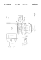
- FIG. 2 illustrates memory 52 in more detail.
- Memory 52 generally includes a memory core 60 which is made up of a number of memory cells. The cells of memory core 60 are accessed during read or write operations using bitlines 62 and wordlines 64. Word lines 64 are selected by row decoder 70 in response to address information on address lines 72. Address lines 68 and 72 may be part of bus 54. Similarly, the bitlines 62 are selected using a column decoder 66 which receives and decodes address information from a plurality of address lines 68.
- Data In bus 74 may be applied to selected bitlines 62 through write path circuitry 76.
- portions of the write path circuitry may be shared by portions of the read path circuitry and, thus, the two are shown as a single block 76.
- Individual cells of a column (associated with the selected bitlines) within memory core 60 are selected by appropriate wordlines 64 and the data from the Data In bus 74 is stored in one or more of the memory cells.
- data is read out of selected memory cells through read path circuitry 76 to a Data Out bus 78.
- Data In bus 74 and Data Out bus 78 may be the same bus (at least in part) and is/are coupled to bus 54. Read and write operations are controlled using one or more control signals 80 (from bus 54) which are decoded and/or buffered using control circuitry 82 to provide appropriate internal control signals 84 to the read/write path circuits 76.
- a typical conventional read/write memory uses SRAM cells as its basic memory cells. Consequently, the memory loses all of its stored information if power is removed or temporarily lost. Accordingly, computer system designers have recognized the need to back up information stored in volatile memories in the event that power is lost, e.g., during a blackout or brownout.
- One way to back up a volatile memory such as an SRAM is to transfer the data stored in the SRAM to a separate non-volatile memory before the power is turned off or is about to fail.
- Unfortunately, such a solution requires that the data be transferred bit-by-bit between the volatile memory and the non-volatile memory.
- Such a data transfer which typically occurs over a slow, serial link, cannot accommodate the large amounts of data stored in modern SRAMs (e.g., of the order of 1-4 Mbits) before a complete failure of power.
- FIG. 3 illustrates a non-volatile static random access memory cell 100.
- Memory cell 100 includes four conventional NMOS transistors: N 1 and N 2 for pull-down and S 1 and S 2 for selecting or transferring data between the cell 100 and the bit lines BL and BL.
- PMOS pull-up transistors P 1 and P 2 are stacked gate, double-poly transistors with a bottom tunnel dielectric, poly-silicon floating gate and a top poly-silicon control gate. The control gates and floating gates are isolated by a thin poly-to-poly coupling dielectric.
- Vcc-Vss With a normal supply voltage (Vcc-Vss) across terminals V 1 -V 2 , memory cell 100 functions exactly like a conventional SRAM cell with unlimited, fast read/write operations.
- a non-volatile (NV) storage operation (as described in the above related patent applications) is shown in FIG. 4 and is enabled by boosting the supply voltage (Vcc-Vss) to a higher or programming voltage (Vpp-Vnn) approximately 2 (Vcc-Vss), such that E ox , the field across the tunnel oxide, ⁇ 8 MV/cm for a specified time (T STORE ) of the order of 1-10 msec.
- Vnn may be equal to Vss.
- T STORE electrons are injected by band-to-band not electron (BBHE) injection into the floating gate of the non-conducting stacked gate PMOS transistor while electrons tend to be removed by Fowler-Nordheim (F-N) tunneling from the floating gate of the conducting stacked gate PMOS transistor.
- BBHE band-to-band not electron
- F-N Fowler-Nordheim
- V T s threshold voltages of the stacked gate PMOS transistors P 1 and P 2 .
- the V T of the "OFF" (i.e., non-conducting) PMOS transistor becomes more positive due to BBHE injection while the V T of the "ON" (i.e., conducting) PMOS transistor tends to become negative due to F-N tunneling current.
- Vcc can be removed indefinitely. During this power down time, the difference in the PMOS V T s will be preserved.
- This kind of imbalance may be created for all the cells 100 in an entire memory core 60 during the storage operation.
- a non-volatile (NV) recall operation may be performed in two stages.
- On power up (Phase 1) the PMOS transistor with a less negative V T becomes conducting or "ON". This was the "OFF" PMOS transistor during the NV storage operation.
- the recalled state of cell 100 is the inverse of the cell state during the NV storage operation.
- one more NV storage operation is performed by raising Vcc to Vpp (and lowering Vss to Vnn if desired).
- Phase 2 a power up period during which the supply voltage to the cell 100 raised from 0 to Vcc. Due to the inversion of states during the dummy storage and recall (Phase 2 power up) operations, the state recalled after the Phase 2 power up is the same as the original state when the first storage operation was performed. Thus, the originally stored state of cell 100 is recovered.
- the "dummy" storage operation allows the original state of memory cell 100 to be recovered, it takes time and also exposes the NVSRAM cell to two high voltage programming cycles, which reduces the reliability of the cell. Accordingly, what is desirable is a new scheme for recovering the originally stored state of an NVSRAM cell.
- the present invention provides an architecture for automatically recovering a stored state of a non-volatile random access memory cell (or cells).
- a circuit that connects a first input of the circuit to a second output of the circuit in response to a first control signal and further connects the first input to a first output of the circuit in response to a second control signal.
- the first and second control signals are generated by a control device.
- the control device may include a non-volatile random access memory cell, which is configured to store a reference state indicating states of non-volatile random access memories before power loss.
- the circuit is configured to select a first bit-line connection path or a second bit-line path according to a logic state of a control signal.
- the control signal may be generated by a non-volatile memory cell. If the control signal is in an active state, the first bit-line connection path is selected and if the control signal is in an inactive state, the second bit-line connection path is selected.
- inventions of the present invention include a circuit configured to be responsive to a control signal and to provide bitline outputs in response to bitline inputs.
- the states of the bitline outputs depend upon the states of the bitline inputs and the control signal.
- the control signal may be provided by a non-volatile static random access memory (SRAM) cell.
- the circuit may include inverting and non-inverting paths or may include crossing and passing circuitry.
- bitline outputs of a memory cell are configured to reflect a state stored in the memory cell prior to a power loss.
- FIG. 1 illustrates a computer system including a memory and a bus
- FIG. 2 illustrates a conventional memory for use in the computer system shown in FIG. 1;
- FIG. 3 illustrates a non-volatile SRAM cell
- FIG. 4 illustrates a storage and recall cycle for a non-volatile SRAM cell
- FIG. 5 illustrates a circuit for automatically recovering or correcting data from a non-volatile SRAM cell according to one embodiment of the present invention
- FIG. 6 illustrates the circuit of FIG. 5 in more detail according to one embodiment of the present invention
- FIG. 7 illustrates a memory having a number of non-volatile SRAM cells and switching circuits according to a further embodiment of the present invention
- FIG. 8 illustrates a memory configured to automatically recover data stored in one or more non-volatile SRAM cells according to yet another embodiment of the present invention.
- FIG. 9 illustrates an alternative circuit for automatically correcting data in accordance with a further embodiment of the present invention.
- NVRAM non-volatile random access memory
- a circuit connects a first input of the circuit to a second output of the circuit in response to a first control signal and further connects the first input to a first output of the circuit in response to a second control signal.
- the circuit may be positioned within a bitline connection path of a memory device.
- the circuit further includes a control device which generates the first and second control signals.
- the control device may be a non-volatile random access memory cell (“NVCell”) configured to store a reference state prior to a power loss to the memory.
- NVCell non-volatile random access memory cell
- the circuit may be configured to select a first bit-line connection path or a second bit-line connection path according to a logic state of a control signal.
- the control signal may be generated by an NVCell. If the control signal is in an active state, the first bitline connection path is selected and if the control is in an inactive state, the second bitline connection path is selected.
- the first bit-line connection path connects a first input of the circuit to a second output thereof and a second input of the circuit to a first output thereof.
- the second bitline connection path connects the first input to the first output and the second input and the second output.
- a circuit is configured to be responsive to a control signal.
- the circuit provides bitline outputs in response to bitline inputs and the states of the bitline outputs depend on the states of the bitline inputs and the control signal.
- the control signal may be provided by a non-volatile SRAM cell.
- the circuit may include a pair of control devices, each having an inverting and non-inverting bitline path or the circuit may include a passing circuit and a crossing circuit. Other embodiments are also described below to more fully illustrate the present invention.
- FIG. 5 illustrates a circuit 300 configured in accordance with one embodiment of the present invention.
- the circuit 300 is configured to connect a first input 310 to a second output 322 in response to a first control signal 314 and the first input 310 to a first output 320 in response to a second control signal 316.
- the first and second control signals 314 and 316 represent states of a control device 302.
- circuit 300 may include a control device 302 and a switching circuit 304.
- the switching circuit 304 is configured to connect the first input 310 to either the first output 320 or the second output 322 according to the state of the first control signal 314.
- the switching circuit 304 receives input signals from input bitlines BL and BL at the first and second inputs 310 and 312, respectively, and provides output signals for output bitlines BL and BL at the first and second outputs 320 and 322, respectively, according to the first and second control signals 314 and 316.
- the switching circuit 304 performs a crossing function, which connects the first and second inputs 310 and 312 to the second and the first outputs 322 and 320, respectively.
- the switching circuit 304 performs a passing function by connecting the first and second inputs 310 and 312 to the first and second outputs 320 and 322, respectively.
- the crossing and passing functions may be performed by a crossing circuit 306 and a passing circuit 308, respectively.
- the crossing circuit 306 is configured to receive the input bitline signals from first and the second inputs 310 and 312 and provides the output bitline signals at first and second outputs 320 and 322 in response to the first control signal 314. In other words, when the first control signal 314 is in an active state, the crossing circuit 306 provides the output bitline signals at first and second outputs 320 and 322 by connecting the first and second inputs 310 and 312 to the second and first outputs 322 and 320, respectively. When the second control signal 316 is in an active state, the passing circuit 308 is configured to provide the output bitline signals at the first and second outputs 320 and 322 by connecting the first and second inputs 310 and 312 to the first and second outputs 320 and 322, respectively.
- the control device 302 may be configured to generate the first and second control signals 314 and 316 according to states stored in the control device 302.
- the second control signal 316 is designed to be the logical complement of the first control signal 314. Thus, if the first control signal 314 is in an inactive state, the second control signal 316 is in an active state and vice-versa.
- FIG. 6 illustrates circuit 300 in more detail.
- control device 302 may be an NVCell.
- NVCell 302 A detailed description of NVCell 302 can be found in the co-pending application Ser. No. 08/885,156, filed Jun. 30, 1997, entitled “Non-Volatile Static Random Access Memory and Methods for Using Same.”
- the NVCell 302 is configured to store a reference state before a power loss (e.g., according to the above-described NV storage operation).
- the reference state is subsequently used to generate the first and second control signals 314 and 316, which are used to control the switching circuit 304.
- first control signal 314 is logical complement of the second control signal 316, generating one control signal (e.g., for other embodiments of the present invention) may be sufficient.
- a complement state of a single control signal may be generated by an inverter.
- circuit 300 may be used to automatically correct data stored in the memory as follows.
- a memory having a plurality of NVCells in a memory core. Each of these cells is coupled to a bitline pair BL and BL as shown in FIG. 3.
- circuit 300 is coupled to BL and BL at inputs 310 and 312.
- Outputs 320 and 322 are coupled to further read path circuitry of the memory.
- circuit 300 provides a bitline connection path from inputs 310 and 312 to outputs 320 and 322 according to the states of control signals 314 and 316.
- the state of a memory cell or cells of the memory are stored (e.g., by raising their operating voltage to a programming voltage as described above). For purposes of this example, assume that the state so stored corresponds to a condition where bitline BL is at a higher potential then bitline BL--a condition indicating that the memory cell stores a logic 1.
- the operating voltage of NVCell 302 is also raised to a programming voltage level and the state of NVCell 302 is stored. Assume that this state corresponds to a situation where control signal 314 is inactive and control signal 316 is active. In such a case, circuit 300 provides a connection from input 310 to output 320 and from input 312 to output 322.
- the read path circuitry of the memory device receives signals on bitline BL and BL such that the potential on BL is higher than on BL and recognizes that the memory cell of the memory core stores a logic 1.
- circuit 300 provides for automatically recovering the data state stored in an NV memory cell prior to a power loss and eliminates the need for a "dummy" storage and recall operation. This functionally is achieved, in the illustrated embodiment, through crossing circuit 306 and passing circuit 308.
- the crossing circuit 306 includes logic elements 411 and 412.
- the logic elements may be n-channel transistors and are gated by control signal 314. In operation, when control signal 314 is active (logic high), input 310 is coupled to output 322 and input 312 is coupled to output 320.
- Other types of transistors e.g., p-channel transistors may be used for logic elements 411 and 412 so long as this overall functionality is maintained.
- the passing circuit 308 includes logic elements 414 and 416, which again may be n-channel transistors.
- Logic element 414 is gated by control signal 316 and, when control signal 316 is active (logic high), couples input 310 to output 320.
- logic element 416 is gated by control signal 316 and, when control signal 316 is active, couples input 312 to output 322.
- control signal 316 is active (logic high)
- control signal 316 couples input 312 to output 322.
- other types of transistors or logic elements may be used so long as this functionality is preserved.
- FIG. 7 illustrates a memory 500 which is an embodiment of present invention.
- Memory 500 includes a bitline switcher 503 that contains n switching circuits 304 coupled to a memory core 501 which contains m rows by n columns of NVCells 502.
- Each pair of bitlines 510 are coupled to a respective switching circuit 304 in the bitline switcher 501 which operate under the control of control device 302.
- Each switching circuit 304 is configured to receive a pair of bitlines 510 from a column 530 as inputs. Each switching circuit 304 provides output signals on bitlines 520 (when bitlines are selected) according to state of a control signal 514. The signals on bitlines 520 are used by the read path circuitry of memory 500 to determine the data stored in NVCells 502 of the memory core 501.
- the control device 302 may be an NVCell and may store a reference state indicating states of NVCells 502 in the memory core 501 before a power loss.
- the control device 302 is configured to generate control signal 514 in response to the reference state.
- the control signal 514 is provided to each switching circuit 304 and may be buffered to increase fan out capability for controlling large numbers of switching circuits 304.
- FIG. 8 further illustrates memory 500, which may be used in a computer system.
- bitline switcher 503 is coupled in a bitline path between memory core 501 and read path circuitry 608.
- control signals 680 are provided to control unit 682.
- Control unit 682 generates a read control signal 684 which activates read path circuit 608.
- read path circuit 608 senses the states of bitline 612 which provide signals from selected memory cells of memory core 501.
- the selected cells of memory core 501 are accessed in the conventional fashion using column decoder 630 and row decoder 640. Read path circuitry 608 then provides data out signal 678.
- the states of the memory cells 502 of memory core 501 may be stored by raising their operating voltage to a programming voltage level.
- the state of NVCell 302 may be stored in a similar fashion. Then, in the event of a power loss and restoration, the cells 502 of memory core 501 will power up in a logically inverse state to that which was stored. So too will NVCell 302 power up in a logically inverse state to that which it stored prior to the power loss.
- As a result signal 514 will have a logical compliment state to that which it had prior to the power loss and switching circuits 304 of bitline switches 503 will provide bitline coupling (inputs to outputs) opposite to that which was provided prior to the power loss.
- the read path circuitry 608 will be provided with signals on bitlines 520 which have the same state as was present prior to the power loss. Accordingly, the data states stored in cells 502 of memory core 501 will be read as being the same as were present prior to the power loss--all without the need for a dummy storage and recall operation.
- bitlines BL will be more positive then bitlines BL at the inputs of respective switching circuit 302 of bitline switches 503. Switching circuits 302 will pass this state to the read path circuits 608 under the control of control signal 514.
- Control signal 514 is produced by control circuit 302, so when control circuit 302 stores a logic 1, control signal 514 is also a logic 1.
- control circuit 302 power up in its logically inverse state and provides a logically inverse control signal 514.
- This control signal 514 is provided to switching circuits 302, which now provide an opposite coupling for the bitlines to that provided prior to the power loss. However, the state seen by the read path circuits remains the same.
- one embodiment of the present invention provides a circuit, e.g., switching circuit 304, which is configured to be responsive to a control signal and to provide bitline outputs (e.g., 320 and 322) in response to bitline inputs (e.g., 310 and 312) depending on the states of the bitline inputs and the control signal.
- the data correction architecture of the present invention encompasses more then just circuit 300 of FIG. 5.
- FIG. 9 illustrates an alternative circuit for automatically correcting data in accordance with a further embodiment of the present invention.
- FIG. 9 shows a circuit 700 which is also configured to be response to a control signal and to provide bitline outputs (e.g., BL' and BL') in response to bitline inputs (e.g., BL and BL).
- bitline outputs e.g., BL' and BL'
- the states of the bitline outputs depend on the states of the bitline inputs, and the state of the control signal.
- a control device 702 which may be a non-volatile static random access memory cell as described above, provides two control signals, 704 and 706. However, as was discussed above, a single control signal may be provided and logically inverted, if necessary.
- Circuit 700 includes two control devices 708 and 710 coupled between the bitline inputs and outputs.
- control device 708 is coupled between bitline input BL and bitline output BL'
- control device 710 is coupled between bitline input BL and bitline output BL'.
- bitline inputs BL and BL may be provided by a memory cell (e.g., an NVRAM cell) of a memory core in a memory device of a computer system.
- bitline outputs BL' and BL' may be provided by circuit 700 to the read path circuitry of the memory device.
- Each of the control devices 708 and 710 are coupled to receive control signals 704 and 706.
- each of the control devices 708 and 710 provide non-inverting bitline paths between the bitline inputs and the bitline outputs and inverting bitline paths between the bitline inputs and the bitline outputs.
- the non-inverting bitline path between bitline input BL and bitline output BL' is through transistor 712.
- the inverting bitline path between BL and BL' is through inverter 714 and transistor 716.
- control signal 704 is logic high (and, necessarily, control signal 706 is logic low)
- the non-inverting bitline path between BL and BL' is selected.
- control signal 706 is logic high (and control signal 704 is logic low
- the inverting bitline path between BL and BL' is selected.
- the state of bitline output BL' is the logical opposite of the state of bitline input BL.
- the non-inverting bitline path between bitline input BL and bitline output BL' is through transistor 718.
- the inverting bitline path between BL and BL' is through inverter 720 and transistor 722.
- control signal 704 is a logic high
- control signal 706 is a logic high
- the inverting path between BL and BL' is selected.
- the state of bitline output BL' is the logical opposite of the state of bitline input BL'.
- circuit 700 allows for configuring the bitline outputs of a memory cell to reflect a state stored in the memory cell prior to a power loss.
- a memory cell or, more preferably an NVRAM cell which provides bitline inputs BL and BL to circuit 700 stores a logic 1.
- the memory cell may now store a logic 0.
- the states of bitline inputs BL and BL will be the logic opposites of the states which were provided prior to the power loss.
- circuit 700 under the control of control signals 704 and 706 (which will also power up in states logically inverse to those which were provided to circuit 700 prior to the power loss), will provide bitline outputs BL' and BL' in the same states as before the power loss.
- the read path circuitry of the memory device will still receive signals which indicate that the memory cell stores a logic 1 (as before the power loss).
- circuit 700 accomplishes this data correction by switching between the inverting or non-inverting bitline paths of control circuits 708 and 710.
- control circuits 708 and 710 will be selected and bitline output BL' will be more positive than BL'.
- control device 702 also powers up in a logically inverse state from that which it had before the power loss, control signal 704 is now logic low, while control signal 706 is logic high. Thus, the inverting paths of each control circuit 708 and 710 are selected.
- Circuit 700 thereby provides the same functionality as circuit 300 and as set forth in Table 1 above.
Landscapes
- Static Random-Access Memory (AREA)
Abstract
Description
              TABLE 1
______________________________________
       Logic               State        State
       State               stored       seen by
       Stored              by Control
                                  Control
                                        Read Path
       by cells
             BL     BL     Circuit
                                  Signal
                                        Circuit
______________________________________
Case 1
Prior to 1       +ve    -ve  1      1     1
Power Loss
After Power
         0       -ve    +ve  0      0     0
Restoration
Case 2
Prior to 0       -ve    +ve  1      1     1
Power Loss
After Power
         1       +ve    -ve  0      0     0
Restoration
______________________________________
Claims (27)
Priority Applications (1)
| Application Number | Priority Date | Filing Date | Title |
|---|---|---|---|
| US08/988,942 US6097618A (en) | 1997-12-11 | 1997-12-11 | Apparatus and method for correcting data in a non-volatile random access memory |
Applications Claiming Priority (1)
| Application Number | Priority Date | Filing Date | Title |
|---|---|---|---|
| US08/988,942 US6097618A (en) | 1997-12-11 | 1997-12-11 | Apparatus and method for correcting data in a non-volatile random access memory |
Publications (1)
| Publication Number | Publication Date |
|---|---|
| US6097618A true US6097618A (en) | 2000-08-01 |
Family
ID=25534617
Family Applications (1)
| Application Number | Title | Priority Date | Filing Date |
|---|---|---|---|
| US08/988,942 Expired - Lifetime US6097618A (en) | 1997-12-11 | 1997-12-11 | Apparatus and method for correcting data in a non-volatile random access memory |
Country Status (1)
| Country | Link |
|---|---|
| US (1) | US6097618A (en) |
Cited By (15)
| Publication number | Priority date | Publication date | Assignee | Title |
|---|---|---|---|---|
| US6278627B1 (en) * | 2000-02-15 | 2001-08-21 | Intel Corporation | Multiple input bit-line detection with phase stealing latch in a memory design |
| US20030028699A1 (en) * | 2001-08-02 | 2003-02-06 | Michael Holtzman | Removable computer with mass storage |
| US20060114020A1 (en) * | 2004-09-24 | 2006-06-01 | Cypress Semiconductor Corporation | One time programmable latch and method |
| US20060268615A1 (en) * | 2005-05-30 | 2006-11-30 | Hynix Semiconductor Inc. | Nonvolatile semiconductor static random access memory device |
| US20070086240A1 (en) * | 2005-10-04 | 2007-04-19 | Thomas Kern | Measuring circuit and reading method for memory cells |
| US7339848B1 (en) | 2005-11-03 | 2008-03-04 | Cypress Semiconductor Corporation | Anti-fuse latch circuit and method including self-test |
| US7426142B1 (en) | 2005-05-05 | 2008-09-16 | Cypress Semiconductor Corporation | Device and method for sensing programming status of non-volatile memory elements |
| US7821859B1 (en) | 2006-10-24 | 2010-10-26 | Cypress Semiconductor Corporation | Adaptive current sense amplifier with direct array access capability |
| US7859906B1 (en) | 2007-03-30 | 2010-12-28 | Cypress Semiconductor Corporation | Circuit and method to increase read margin in non-volatile memories using a differential sensing circuit |
| US7859925B1 (en) | 2006-03-31 | 2010-12-28 | Cypress Semiconductor Corporation | Anti-fuse latch self-test circuit and method |
| US20110044109A1 (en) * | 2009-08-18 | 2011-02-24 | Ping-Chia Shih | Non-volatile static random access memory (nvsram) device |
| US8072834B2 (en) | 2005-08-25 | 2011-12-06 | Cypress Semiconductor Corporation | Line driver circuit and method with standby mode of operation |
| FR3008534A1 (en) * | 2013-07-09 | 2015-01-16 | St Microelectronics Rousset | METHOD FOR MANAGING THE OPERATION OF A MEMORY DEVICE HAVING A MEMORY PLAN OF THE SRAM TYPE AND A MEMORY PLAN OF THE NON-VOLATILE TYPE, AND MEMORY DEVICE CORRESPONDING THERETO |
| US9431108B2 (en) | 2014-03-21 | 2016-08-30 | Stmicroelectronics (Rousset) Sas | Integrated structure comprising neighboring transistors |
| US9728248B2 (en) | 2014-03-21 | 2017-08-08 | Stmicroelectronics (Rousset) Sas | Semiconductor structure and memory device including the structure |
Citations (17)
| Publication number | Priority date | Publication date | Assignee | Title |
|---|---|---|---|---|
| US3906464A (en) * | 1974-06-03 | 1975-09-16 | Motorola Inc | External data control preset system for inverting cell random access memory |
| US4000413A (en) * | 1975-05-27 | 1976-12-28 | Intel Corporation | Mos-ram |
| US4051388A (en) * | 1975-05-07 | 1977-09-27 | Nippon Electric Company, Ltd. | Flip-flop accompanied by two current switches, one having a smaller current sink capability than the other |
| US4096584A (en) * | 1977-01-31 | 1978-06-20 | Intel Corporation | Low power/high speed static ram |
| US4110639A (en) * | 1976-12-09 | 1978-08-29 | Texas Instruments Incorporated | Address buffer circuit for high speed semiconductor memory |
| US4146802A (en) * | 1977-09-19 | 1979-03-27 | Motorola, Inc. | Self latching buffer |
| US4149099A (en) * | 1976-09-10 | 1979-04-10 | Nippon Electric Co., Ltd. | Amplifier circuit for obtaining true and complementary output signals from an input signal |
| US4216395A (en) * | 1978-01-16 | 1980-08-05 | Bell Telephone Laboratories, Incorporated | Detector circuitry |
| US4262219A (en) * | 1977-10-07 | 1981-04-14 | Compagnie Internationale Pour L'informatique Cil Honeywell Bull (Societe Anonyme) | Circuit for generating phases to control the carrying out of operations in a data processing system |
| US4291242A (en) * | 1979-05-21 | 1981-09-22 | Motorola, Inc. | Driver circuit for use in an output buffer |
| US4347448A (en) * | 1980-11-07 | 1982-08-31 | Mostek Corporation | Buffer circuit for semiconductor memory |
| US4433252A (en) * | 1982-01-18 | 1984-02-21 | International Business Machines Corporation | Input signal responsive pulse generating and biasing circuit for integrated circuits |
| US4472643A (en) * | 1980-09-26 | 1984-09-18 | Tokyo Shibaura Denki Kabushiki Kaisha | Dynamic signal generation circuit |
| US4716552A (en) * | 1985-03-29 | 1987-12-29 | Advanced Micro Devices, Inc. | Method and apparatus for non-destructive access of volatile and non-volatile data in a shadow memory array |
| US5517448A (en) * | 1994-09-09 | 1996-05-14 | United Microelectronics Corp. | Bias circuit for virtual ground non-volatile memory array with bank selector |
| US5621696A (en) * | 1996-01-26 | 1997-04-15 | Ibm Corporation | Virtual multiple-read port memory array |
| US5793684A (en) * | 1997-07-10 | 1998-08-11 | Microchip Technology Incorporated | Memory device having selectable redundancy for high endurance and reliability and method therefor |
-
1997
- 1997-12-11 US US08/988,942 patent/US6097618A/en not_active Expired - Lifetime
Patent Citations (17)
| Publication number | Priority date | Publication date | Assignee | Title |
|---|---|---|---|---|
| US3906464A (en) * | 1974-06-03 | 1975-09-16 | Motorola Inc | External data control preset system for inverting cell random access memory |
| US4051388A (en) * | 1975-05-07 | 1977-09-27 | Nippon Electric Company, Ltd. | Flip-flop accompanied by two current switches, one having a smaller current sink capability than the other |
| US4000413A (en) * | 1975-05-27 | 1976-12-28 | Intel Corporation | Mos-ram |
| US4149099A (en) * | 1976-09-10 | 1979-04-10 | Nippon Electric Co., Ltd. | Amplifier circuit for obtaining true and complementary output signals from an input signal |
| US4110639A (en) * | 1976-12-09 | 1978-08-29 | Texas Instruments Incorporated | Address buffer circuit for high speed semiconductor memory |
| US4096584A (en) * | 1977-01-31 | 1978-06-20 | Intel Corporation | Low power/high speed static ram |
| US4146802A (en) * | 1977-09-19 | 1979-03-27 | Motorola, Inc. | Self latching buffer |
| US4262219A (en) * | 1977-10-07 | 1981-04-14 | Compagnie Internationale Pour L'informatique Cil Honeywell Bull (Societe Anonyme) | Circuit for generating phases to control the carrying out of operations in a data processing system |
| US4216395A (en) * | 1978-01-16 | 1980-08-05 | Bell Telephone Laboratories, Incorporated | Detector circuitry |
| US4291242A (en) * | 1979-05-21 | 1981-09-22 | Motorola, Inc. | Driver circuit for use in an output buffer |
| US4472643A (en) * | 1980-09-26 | 1984-09-18 | Tokyo Shibaura Denki Kabushiki Kaisha | Dynamic signal generation circuit |
| US4347448A (en) * | 1980-11-07 | 1982-08-31 | Mostek Corporation | Buffer circuit for semiconductor memory |
| US4433252A (en) * | 1982-01-18 | 1984-02-21 | International Business Machines Corporation | Input signal responsive pulse generating and biasing circuit for integrated circuits |
| US4716552A (en) * | 1985-03-29 | 1987-12-29 | Advanced Micro Devices, Inc. | Method and apparatus for non-destructive access of volatile and non-volatile data in a shadow memory array |
| US5517448A (en) * | 1994-09-09 | 1996-05-14 | United Microelectronics Corp. | Bias circuit for virtual ground non-volatile memory array with bank selector |
| US5621696A (en) * | 1996-01-26 | 1997-04-15 | Ibm Corporation | Virtual multiple-read port memory array |
| US5793684A (en) * | 1997-07-10 | 1998-08-11 | Microchip Technology Incorporated | Memory device having selectable redundancy for high endurance and reliability and method therefor |
Cited By (27)
| Publication number | Priority date | Publication date | Assignee | Title |
|---|---|---|---|---|
| US6278627B1 (en) * | 2000-02-15 | 2001-08-21 | Intel Corporation | Multiple input bit-line detection with phase stealing latch in a memory design |
| US20030028699A1 (en) * | 2001-08-02 | 2003-02-06 | Michael Holtzman | Removable computer with mass storage |
| US8176335B2 (en) | 2001-08-02 | 2012-05-08 | Sandisk Technologies Inc. | Removable computer with mass storage |
| US7418344B2 (en) * | 2001-08-02 | 2008-08-26 | Sandisk Corporation | Removable computer with mass storage |
| US20080288700A1 (en) * | 2001-08-02 | 2008-11-20 | Michael Holtzman | Removable computer with mass storage |
| US20080295167A1 (en) * | 2001-08-02 | 2008-11-27 | Michael Holtzman | Removable computer with mass storage |
| US20060114020A1 (en) * | 2004-09-24 | 2006-06-01 | Cypress Semiconductor Corporation | One time programmable latch and method |
| US7342836B2 (en) | 2004-09-24 | 2008-03-11 | Cypress Semiconductor Corporation | One time programmable latch and method |
| US7426142B1 (en) | 2005-05-05 | 2008-09-16 | Cypress Semiconductor Corporation | Device and method for sensing programming status of non-volatile memory elements |
| US20060268615A1 (en) * | 2005-05-30 | 2006-11-30 | Hynix Semiconductor Inc. | Nonvolatile semiconductor static random access memory device |
| US7307872B2 (en) * | 2005-05-30 | 2007-12-11 | Hynix Semiconductor Inc. | Nonvolatile semiconductor static random access memory device |
| US8072834B2 (en) | 2005-08-25 | 2011-12-06 | Cypress Semiconductor Corporation | Line driver circuit and method with standby mode of operation |
| US7646647B2 (en) * | 2005-10-04 | 2010-01-12 | Qimonda Ag | Measuring circuit and reading method for memory cells |
| US20070086240A1 (en) * | 2005-10-04 | 2007-04-19 | Thomas Kern | Measuring circuit and reading method for memory cells |
| US7339848B1 (en) | 2005-11-03 | 2008-03-04 | Cypress Semiconductor Corporation | Anti-fuse latch circuit and method including self-test |
| US7859925B1 (en) | 2006-03-31 | 2010-12-28 | Cypress Semiconductor Corporation | Anti-fuse latch self-test circuit and method |
| US7821859B1 (en) | 2006-10-24 | 2010-10-26 | Cypress Semiconductor Corporation | Adaptive current sense amplifier with direct array access capability |
| US7859906B1 (en) | 2007-03-30 | 2010-12-28 | Cypress Semiconductor Corporation | Circuit and method to increase read margin in non-volatile memories using a differential sensing circuit |
| US20110044109A1 (en) * | 2009-08-18 | 2011-02-24 | Ping-Chia Shih | Non-volatile static random access memory (nvsram) device |
| US8018768B2 (en) | 2009-08-18 | 2011-09-13 | United Microelectronics Corp. | Non-volatile static random access memory (NVSRAM) device |
| US8792275B2 (en) | 2009-08-18 | 2014-07-29 | United Microelectronics Corp. | Non-volatile static random access memory (NVSRAM) device |
| FR3008534A1 (en) * | 2013-07-09 | 2015-01-16 | St Microelectronics Rousset | METHOD FOR MANAGING THE OPERATION OF A MEMORY DEVICE HAVING A MEMORY PLAN OF THE SRAM TYPE AND A MEMORY PLAN OF THE NON-VOLATILE TYPE, AND MEMORY DEVICE CORRESPONDING THERETO |
| US9123413B2 (en) | 2013-07-09 | 2015-09-01 | Stmicroelectronics (Rousset) Sas | Method for managing the operation of a memory device having a SRAM memory plane and a non volatile memory plane, and corresponding memory device |
| US9431108B2 (en) | 2014-03-21 | 2016-08-30 | Stmicroelectronics (Rousset) Sas | Integrated structure comprising neighboring transistors |
| US9728248B2 (en) | 2014-03-21 | 2017-08-08 | Stmicroelectronics (Rousset) Sas | Semiconductor structure and memory device including the structure |
| US9780098B2 (en) | 2014-03-21 | 2017-10-03 | Stmicroelectronics (Rousset) Sas | Integrated structure comprising neighboring transistors |
| US10304524B2 (en) | 2014-03-21 | 2019-05-28 | Stmicroelectronics (Rousset) Sas | Semiconductor structure and memory device including the structure |
Similar Documents
| Publication | Publication Date | Title |
|---|---|---|
| US5986932A (en) | Non-volatile static random access memory and methods for using same | |
| US5914895A (en) | Non-volatile random access memory and methods for making and configuring same | |
| US6055187A (en) | Sensing circuitry for reading and verifying the contents of electrically programmable/erasable non-volatile memory cells | |
| US6731530B2 (en) | Shadow RAM cell using a ferroelectric capacitor | |
| US6205049B1 (en) | Five-transistor SRAM cell | |
| KR100228622B1 (en) | Read / Write Memory with Improved Write Driver | |
| KR100228621B1 (en) | Semiconductor memory having columns that equalize as data changes during a write cycle | |
| US6097618A (en) | Apparatus and method for correcting data in a non-volatile random access memory | |
| US6798700B2 (en) | Methods of reading and/or writing data to memory devices including multiple write circuits and/or virtual ground lines and related devices | |
| EP0028935A2 (en) | Nonvolatile semiconductor memory circuits | |
| KR100310358B1 (en) | Fast programmable circuit device structure with zero power | |
| EP0755057B1 (en) | Semiconductor memory device | |
| JPH11219589A (en) | Static semiconductor memory device | |
| US5113374A (en) | Mos type semiconductor memory device having a word line resetting circuit | |
| US5243569A (en) | Differential cell-type eprom incorporating stress test circuit | |
| JPH0945081A (en) | Static memory | |
| US4939691A (en) | Static random access memory | |
| US4985864A (en) | Static random access memory having column decoded bit line bias | |
| US5696716A (en) | Programmable memory element | |
| US6717866B2 (en) | SRAM power-up system and method | |
| US5361229A (en) | Precharging bitlines for robust reading of latch data | |
| US5894434A (en) | MOS static memory array | |
| US5305258A (en) | Semiconductor memory and memory cell | |
| US5245579A (en) | Semiconductor memory device | |
| EP0321847B1 (en) | Semiconductor memory capable of improving data rewrite speed |
Legal Events
| Date | Code | Title | Description |
|---|---|---|---|
| AS | Assignment |
Owner name: CYPRESS SEMICONDUCTOR CORPORATION, CALIFORNIA Free format text: ASSIGNMENT OF ASSIGNORS INTEREST;ASSIGNOR:JENNE, FREDRICK B.;REEL/FRAME:008909/0967 Effective date: 19971204 |
|
| STCF | Information on status: patent grant |
Free format text: PATENTED CASE |
|
| FPAY | Fee payment |
Year of fee payment: 4 |
|
| FEPP | Fee payment procedure |
Free format text: PAYOR NUMBER ASSIGNED (ORIGINAL EVENT CODE: ASPN); ENTITY STATUS OF PATENT OWNER: LARGE ENTITY |
|
| FPAY | Fee payment |
Year of fee payment: 8 |
|
| REMI | Maintenance fee reminder mailed | ||
| FPAY | Fee payment |
Year of fee payment: 12 |
|
| AS | Assignment |
Owner name: MORGAN STANLEY SENIOR FUNDING, INC., NEW YORK Free format text: SECURITY INTEREST;ASSIGNORS:CYPRESS SEMICONDUCTOR CORPORATION;SPANSION LLC;REEL/FRAME:035240/0429 Effective date: 20150312 |
|
| AS | Assignment |
Owner name: SPANSION LLC, CALIFORNIA Free format text: PARTIAL RELEASE OF SECURITY INTEREST IN PATENTS;ASSIGNOR:MORGAN STANLEY SENIOR FUNDING, INC., AS COLLATERAL AGENT;REEL/FRAME:039708/0001 Effective date: 20160811 Owner name: CYPRESS SEMICONDUCTOR CORPORATION, CALIFORNIA Free format text: PARTIAL RELEASE OF SECURITY INTEREST IN PATENTS;ASSIGNOR:MORGAN STANLEY SENIOR FUNDING, INC., AS COLLATERAL AGENT;REEL/FRAME:039708/0001 Effective date: 20160811 |
|
| AS | Assignment |
Owner name: MONTEREY RESEARCH, LLC, CALIFORNIA Free format text: ASSIGNMENT OF ASSIGNORS INTEREST;ASSIGNOR:CYPRESS SEMICONDUCTOR CORPORATION;REEL/FRAME:040911/0238 Effective date: 20160811 |
|
| AS | Assignment |
Owner name: MORGAN STANLEY SENIOR FUNDING, INC., NEW YORK Free format text: CORRECTIVE ASSIGNMENT TO CORRECT THE 8647899 PREVIOUSLY RECORDED ON REEL 035240 FRAME 0429. ASSIGNOR(S) HEREBY CONFIRMS THE SECURITY INTERST;ASSIGNORS:CYPRESS SEMICONDUCTOR CORPORATION;SPANSION LLC;REEL/FRAME:058002/0470 Effective date: 20150312 |