US6095953A - Magnetic control of exercise bicycle - Google Patents
Magnetic control of exercise bicycle Download PDFInfo
- Publication number
- US6095953A US6095953A US09/211,272 US21127298A US6095953A US 6095953 A US6095953 A US 6095953A US 21127298 A US21127298 A US 21127298A US 6095953 A US6095953 A US 6095953A
- Authority
- US
- United States
- Prior art keywords
- wheel
- seat
- magnetic
- magnets
- bicycle frame
- Prior art date
- Legal status (The legal status is an assumption and is not a legal conclusion. Google has not performed a legal analysis and makes no representation as to the accuracy of the status listed.)
- Expired - Fee Related
Links
Images


Classifications
-
- A—HUMAN NECESSITIES
- A63—SPORTS; GAMES; AMUSEMENTS
- A63B—APPARATUS FOR PHYSICAL TRAINING, GYMNASTICS, SWIMMING, CLIMBING, OR FENCING; BALL GAMES; TRAINING EQUIPMENT
- A63B21/00—Exercising apparatus for developing or strengthening the muscles or joints of the body by working against a counterforce, with or without measuring devices
- A63B21/005—Exercising apparatus for developing or strengthening the muscles or joints of the body by working against a counterforce, with or without measuring devices using electromagnetic or electric force-resisters
- A63B21/0051—Exercising apparatus for developing or strengthening the muscles or joints of the body by working against a counterforce, with or without measuring devices using electromagnetic or electric force-resisters using eddy currents induced in moved elements, e.g. by permanent magnets
-
- A—HUMAN NECESSITIES
- A63—SPORTS; GAMES; AMUSEMENTS
- A63B—APPARATUS FOR PHYSICAL TRAINING, GYMNASTICS, SWIMMING, CLIMBING, OR FENCING; BALL GAMES; TRAINING EQUIPMENT
- A63B21/00—Exercising apparatus for developing or strengthening the muscles or joints of the body by working against a counterforce, with or without measuring devices
- A63B21/00058—Mechanical means for varying the resistance
- A63B21/00069—Setting or adjusting the resistance level; Compensating for a preload prior to use, e.g. changing length of resistance or adjusting a valve
-
- A—HUMAN NECESSITIES
- A63—SPORTS; GAMES; AMUSEMENTS
- A63B—APPARATUS FOR PHYSICAL TRAINING, GYMNASTICS, SWIMMING, CLIMBING, OR FENCING; BALL GAMES; TRAINING EQUIPMENT
- A63B22/00—Exercising apparatus specially adapted for conditioning the cardio-vascular system, for training agility or co-ordination of movements
- A63B22/06—Exercising apparatus specially adapted for conditioning the cardio-vascular system, for training agility or co-ordination of movements with support elements performing a rotating cycling movement, i.e. a closed path movement
- A63B22/0605—Exercising apparatus specially adapted for conditioning the cardio-vascular system, for training agility or co-ordination of movements with support elements performing a rotating cycling movement, i.e. a closed path movement performing a circular movement, e.g. ergometers
Definitions
- the present invention relates generally to an exercise bicycle, and more particularly to an improved control of magnetic resistance for an exercise bicycle.
- the conventional exercise bicycle body (as shown in FIGS. 1 and 2) has a control for magnetic resistance constructed on the bicycle frame 11 which is fastened pivotally with the magnetic wheel 12.
- the magnetic wheel 12 is lined with a non-magnetic layer 13 on the rim.
- the arc-shaped seat for magnets 15 with magnetic pieces 14 is fixed at an interior edge of the bicycle frame 11 beneath the magnetic wheel 12.
- the arc-shaped seat 15 uses an adjustment device 16 to adjust the space between the magnetic pieces 14 and the magnetic wheel 12 for controlling and damping the force of turning the magnetic wheel (as shown in FIGS. 3 and 4).
- the positioning causes the magnetic wheel 12 to be able to be easily deviated from its pivoting place on the frame 11 after being used over a long period of time; and furthermore, it causes the free space between the magnetic wheel 12 and the arc-shaped seat 15 to change such that the adjustment device 16 is not able to accurately change and control the magnetic resistance of damping force.
- the primary objective of the present invention is to provide an improved control of magnetic resistance for an exercise bicycle which is free from the drawbacks of the non-magnetic layer installation as found in the prior art exercise bicycles as described above.
- the present invention has a non-magnetic layer lined directly onto the interior edge of the arc-shaped seat for magnets to match the curve of the magnetic wheel.
- Such special construction in design provides stable protection.
- the installation of the non-magnetic layer accurately matches the curve of the magnetic wheel.
- the effect on control of magnetic resistance is excellent.
- the construction is cost-effective.
- the present invention focuses on improving upon the drawback of prior art magnetic wheels when the wheel deviates and changes the free space between the wheel and the arc-shaped seat.
- the present invention is constructed to include a through hole, a guide trough of a suspension arm, an elongated hole for a suspension bar, thread, and nut of a suspender so as to improve the stability of the magnetic wheel and the free space between the arc-shaped seat.
- FIG. 1 shows a side view of a prior art exercise bicycle.
- FIG. 2 shows a partial perspective view of a magnetic control device of the prior art exercise bicycle.
- FIG. 3 shows partial side view of the magnetic control device of the prior art exercise bicycle.
- FIG. 4 shows a schematic view of the magnetic control device of the prior art exercise bicycle in adjusting operation.
- FIG. 5 shows a side view of the present invention.
- FIG. 6 shows partial exploded view of the magnetic control device of the present invention.
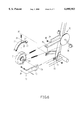
- FIG. 7 shows a schematic view of the magnetic control device of the present invention in adjusting operation.
- the present invention for an improved control of magnetic resistance for an exercise bicycle is comprised of a magnetic wheel 21, an arc-shaped seat for magnets 26, and a non-magnetic layer 28.
- the magnetic wheel 21 is fastened rotatably on the fork structure 23 of the bicycle frame 22 and moved by the pedal 24 which drives the bicycle chain link motion 25.
- the arc-shaped seat 26 uses the suspended device 30 to mount directly along the curve of the magnetic wheel 22, so as to enable each magnetic piece 27 located at the interior edge of the arc-shaped seat 26 to closely contact the surface of the magnetic wheel 21.
- the non-magnetic layer 28 is positioned adjacent the interior surface of the arc-shaped seat 26 over the magnetic pieces 27.
- the present invention stabilizes the arc-shaped seat 26 by the installation of the non-magnetic layer adjacent the interior surface thereof.
- the suspended device 30 is comprised of a suspension arm 31, a suspension bar 34, and a suspender 36.
- the suspension arm 31 forms a guide trough 32 at the inner end thereof for engaging the fork structure 23 of the bicycle frame 22 and provides a through hole 33 for aligning the axle 29 of the magnetic wheel 21. Therefore, the suspension arm 31 aligns onto the axle 29 of the magnetic wheel 21 to fasten onto the fork structure 23 of bicycle frame 22.
- the outer end of the suspension arm 31 provides a pivot for the lower end of the arc-shaped seat 26 so that the interior edge of the arc-shaped seat faces the surface of the magnetic wheel 21.
- the suspension bar 34 is affixed to the bicycle frame 22 and includes an elongated hole 35 which corresponds to the upper end of the arc-shaped seat 26.
- the suspender 36 is affixed to the surface of the arc-shaped seat 26 at one end thereof and has a threaded end 37 at the opposite top end thereof.
- the threaded end 37 passes through the elongated hole 35 and uses the nut 38 to fasten to the top of the suspension bar 34.
- the present invention can therefore achieve stability for the free space between the magnetic wheel 21 and the arc-shaped seat 26.
- the feature of the present invention is the non-magnetic layer 28 directly lined onto the magnetic pieces on the interior edge of the arc-shaped seat, so that the non-magnetic layer accurately matches the curve of the magnetic wheel 21.
- Another feature of the present invention is the suspension arm 31 of the suspended device 30 which uses through hole 33 to mount the axle 29 of the magnetic wheel 21, and also uses the guide trough 32 to engage the fork structure 23 of bicycle frame 22. Therefore, the mounting of the lower end of the arc-shaped seat 26 at the outer end of the aligned suspension arm 31 allows the arc-shaped seat 26 and the magnetic wheel 21 to deviate at the same time and maintain the free space therebetween, when it is used for a long time.
- the elongated hole 35 of the suspension bar 34 allows the suspender 36, that is connected to the arc-shaped seat 26, to move and slide along the elongated hole 35. As a result, it is possible to adjust the distance between the magnetic wheel 21 and the arc-shaped seat for magnets 26 to change and control the magnetic resistance of the damping force.
Abstract
A magnetic resistance control apparatus for an exercise bicycle including a bicycle frame having a fork structure extending therefrom, a wheel having a magnetic surface thereon rotatably mounted on an axle within the fork structure, a pedal assembly rotatably connected to the bicycle frame and linked to the wheel such that a rotation of the pedal assembly causes a rotation of the wheel, a suspension arm connected to the fork structure and extending outwardly therefrom so as to have an end positioned beyond an outer diameter of the wheel, a suspension bar connected to the bicycle frame and extending therefrom so as to be positioned above an outer diameter of the wheel, an arc-shaped seat having magnets received on an interior surface thereof, extending around a portion of the wheel such that the magnets face the magnetic surface of the wheel, and a non-magnetic layer extending directly over the magnets of the seat so as to be interposed between the magnets and the wheel. The seat has an end pivotally connected to the end of the suspension arm. The seat is adjustably connected to the suspension bar so as to set a distance of the magnets from the wheel.
Description
The present invention relates generally to an exercise bicycle, and more particularly to an improved control of magnetic resistance for an exercise bicycle.
The conventional exercise bicycle body (as shown in FIGS. 1 and 2) has a control for magnetic resistance constructed on the bicycle frame 11 which is fastened pivotally with the magnetic wheel 12. The magnetic wheel 12 is lined with a non-magnetic layer 13 on the rim. The arc-shaped seat for magnets 15 with magnetic pieces 14 is fixed at an interior edge of the bicycle frame 11 beneath the magnetic wheel 12. The arc-shaped seat 15 uses an adjustment device 16 to adjust the space between the magnetic pieces 14 and the magnetic wheel 12 for controlling and damping the force of turning the magnetic wheel (as shown in FIGS. 3 and 4).
However, such construction as described above is defective in design because the surface of the magnetic wheel 12 still needs to be lined with a non-magnetic layer 13. Therefore, if the lining of the non-magnetic layer 13 is not stable, then it will easily fall off; and furthermore, if the curvature of the lining of the non-magnetic layer 13 is different from the magnetic wheel 12, then it will affect the rotational inertia of the magnetic wheel 12, or even rub against the magnets of the arc-shaped seat 15.
In addition, because the magnetic wheel 12 and arc-shaped seat 15 are fastened on the bicycle frame 11, the positioning causes the magnetic wheel 12 to be able to be easily deviated from its pivoting place on the frame 11 after being used over a long period of time; and furthermore, it causes the free space between the magnetic wheel 12 and the arc-shaped seat 15 to change such that the adjustment device 16 is not able to accurately change and control the magnetic resistance of damping force.
The primary objective of the present invention is to provide an improved control of magnetic resistance for an exercise bicycle which is free from the drawbacks of the non-magnetic layer installation as found in the prior art exercise bicycles as described above.
The present invention has a non-magnetic layer lined directly onto the interior edge of the arc-shaped seat for magnets to match the curve of the magnetic wheel. Such special construction in design provides stable protection. The installation of the non-magnetic layer accurately matches the curve of the magnetic wheel. The effect on control of magnetic resistance is excellent. Furthermore, the construction is cost-effective.
Another feature of the present invention focuses on improving upon the drawback of prior art magnetic wheels when the wheel deviates and changes the free space between the wheel and the arc-shaped seat. The present invention is constructed to include a through hole, a guide trough of a suspension arm, an elongated hole for a suspension bar, thread, and nut of a suspender so as to improve the stability of the magnetic wheel and the free space between the arc-shaped seat.
The foregoing objective, features, functions and advantages of the present invention will be more readily understood upon a thoughtful deliberation of the following detailed description of a preferred embodiment of the present invention with reference to the accompanying drawings.
FIG. 1 shows a side view of a prior art exercise bicycle.
FIG. 2 shows a partial perspective view of a magnetic control device of the prior art exercise bicycle.
FIG. 3 shows partial side view of the magnetic control device of the prior art exercise bicycle.
FIG. 4 shows a schematic view of the magnetic control device of the prior art exercise bicycle in adjusting operation.
FIG. 5 shows a side view of the present invention.
FIG. 6 shows partial exploded view of the magnetic control device of the present invention.
FIG. 7 shows a schematic view of the magnetic control device of the present invention in adjusting operation.
As shown in FIGS. 5 and 6, the present invention for an improved control of magnetic resistance for an exercise bicycle is comprised of a magnetic wheel 21, an arc-shaped seat for magnets 26, and a non-magnetic layer 28.
The magnetic wheel 21 is fastened rotatably on the fork structure 23 of the bicycle frame 22 and moved by the pedal 24 which drives the bicycle chain link motion 25.
The arc-shaped seat 26 uses the suspended device 30 to mount directly along the curve of the magnetic wheel 22, so as to enable each magnetic piece 27 located at the interior edge of the arc-shaped seat 26 to closely contact the surface of the magnetic wheel 21.
The non-magnetic layer 28 is positioned adjacent the interior surface of the arc-shaped seat 26 over the magnetic pieces 27.
With the construction as described above, the present invention stabilizes the arc-shaped seat 26 by the installation of the non-magnetic layer adjacent the interior surface thereof.
As shown in FIGS. 6 and 7, the suspended device 30 is comprised of a suspension arm 31, a suspension bar 34, and a suspender 36.
The suspension arm 31 forms a guide trough 32 at the inner end thereof for engaging the fork structure 23 of the bicycle frame 22 and provides a through hole 33 for aligning the axle 29 of the magnetic wheel 21. Therefore, the suspension arm 31 aligns onto the axle 29 of the magnetic wheel 21 to fasten onto the fork structure 23 of bicycle frame 22. In addition, the outer end of the suspension arm 31 provides a pivot for the lower end of the arc-shaped seat 26 so that the interior edge of the arc-shaped seat faces the surface of the magnetic wheel 21.
The suspension bar 34 is affixed to the bicycle frame 22 and includes an elongated hole 35 which corresponds to the upper end of the arc-shaped seat 26.
The suspender 36 is affixed to the surface of the arc-shaped seat 26 at one end thereof and has a threaded end 37 at the opposite top end thereof. The threaded end 37 passes through the elongated hole 35 and uses the nut 38 to fasten to the top of the suspension bar 34.
With the construction of the suspended device 30 as described above, the present invention can therefore achieve stability for the free space between the magnetic wheel 21 and the arc-shaped seat 26.
The feature of the present invention is the non-magnetic layer 28 directly lined onto the magnetic pieces on the interior edge of the arc-shaped seat, so that the non-magnetic layer accurately matches the curve of the magnetic wheel 21.
Another feature of the present invention is the suspension arm 31 of the suspended device 30 which uses through hole 33 to mount the axle 29 of the magnetic wheel 21, and also uses the guide trough 32 to engage the fork structure 23 of bicycle frame 22. Therefore, the mounting of the lower end of the arc-shaped seat 26 at the outer end of the aligned suspension arm 31 allows the arc-shaped seat 26 and the magnetic wheel 21 to deviate at the same time and maintain the free space therebetween, when it is used for a long time. In addition, the elongated hole 35 of the suspension bar 34 allows the suspender 36, that is connected to the arc-shaped seat 26, to move and slide along the elongated hole 35. As a result, it is possible to adjust the distance between the magnetic wheel 21 and the arc-shaped seat for magnets 26 to change and control the magnetic resistance of the damping force.
The embodiment of the present invention described above is to be deemed in all respects as being merely illustrative and not restrictive. Accordingly, the present invention may be embodied in other specific forms without deviating from the spirit thereof. The present invention is therefore to be limited only by the scope of the following appended claim.
Claims (1)
1. A magnetic resistance control apparatus comprising:
a bicycle frame having a fork structure extending therefrom;
a wheel having a magnetic surface thereon, said wheel being rotatably mounted on an axle received by said fork structure;
a pedal assembly rotatably connected to said bicycle frame, said pedal assembly being connected by linkage to said wheel such that a rotation of said pedal assembly causes a rotation of said wheel;
a suspension arm connected to said fork structure and extending outwardly therefrom so as to have an end positioned beyond an outer diameter of said wheel, said suspension arm having a guide trough formed thereon, said guide trough engaging said fork structure of said bicycle frame, said suspension arm having a through hole formed therein, said through hole rotatably receiving said axle therein;
a suspension bar connected to said bicycle frame and extending therefrom so as to be positioned above an outer diameter of said wheel, said suspension bar having an elongated hole formed therein;
an arc-shaped seat having magnets received on an interior surface thereof, said seat having an end pivotally connected at said end of said suspension arm, said seat extending around a portion of said wheel such that said magnets face said magnetic surface of said wheel, said seat being adjustably connected to said suspension bar so as to set a distance of said magnets from said wheel, said suspension bar positioned above said seat;
a non-magnetic layer permeable to magnetic forces, said non-magnetic layer extending directly over said magnets of said seat so as to be interposed between said magnets and said wheel;
a suspender affixed at one end to said seat, said suspender having a screw thread at an opposite end thereof, said suspender extending through said elongated hole such that said screw thread resides above said suspension bar; and
a nut adjustably secured to said screw thread of said suspender, said nut contacting a top surface of said suspension bar.
Priority Applications (1)
| Application Number | Priority Date | Filing Date | Title |
|---|---|---|---|
| US09/211,272 US6095953A (en) | 1998-12-14 | 1998-12-14 | Magnetic control of exercise bicycle |
Applications Claiming Priority (1)
| Application Number | Priority Date | Filing Date | Title |
|---|---|---|---|
| US09/211,272 US6095953A (en) | 1998-12-14 | 1998-12-14 | Magnetic control of exercise bicycle |
Publications (1)
| Publication Number | Publication Date |
|---|---|
| US6095953A true US6095953A (en) | 2000-08-01 |
Family
ID=22786219
Family Applications (1)
| Application Number | Title | Priority Date | Filing Date |
|---|---|---|---|
| US09/211,272 Expired - Fee Related US6095953A (en) | 1998-12-14 | 1998-12-14 | Magnetic control of exercise bicycle |
Country Status (1)
| Country | Link |
|---|---|
| US (1) | US6095953A (en) |
Cited By (16)
| Publication number | Priority date | Publication date | Assignee | Title |
|---|---|---|---|---|
| US6244990B1 (en) * | 2000-09-08 | 2001-06-12 | Tong-Sheng Cheng | Magnetic damping device for an exercising machine |
| US6569063B2 (en) * | 2001-07-06 | 2003-05-27 | Tsung-Yu Chen | Magnets adjusting device for bike exercisers |
| US20030158016A1 (en) * | 2002-01-23 | 2003-08-21 | Kolda Clint D. | Variable magnetic resistance unit for an exercise device |
| EP1340523A1 (en) * | 2002-03-01 | 2003-09-03 | Federico Gramaccioni | Pedalling simulating implement with means for adjusting the pedalling effort depending on the inclination |
| US20040166996A1 (en) * | 2003-02-20 | 2004-08-26 | Kolda Clint D. | Exercise device with an adjustable magnetic resistance arrangement |
| US20050159274A1 (en) * | 2004-01-20 | 2005-07-21 | Chao-Chuan Chen | Damper adjusting device for exercise apparatus |
| US20050209520A1 (en) * | 2004-03-16 | 2005-09-22 | Chang Yow Industry Co., Ltd. | Two-node-type human physiological parameter measuring apparatus |
| US7004888B1 (en) * | 2005-01-03 | 2006-02-28 | Yen Shu Weng | Exerciser having magnetic retarding device |
| US7077789B1 (en) * | 2005-05-11 | 2006-07-18 | Michael Lin | Adjustable magnetic resistance mechanism for upright bikes |
| US20080171641A1 (en) * | 2007-01-12 | 2008-07-17 | Yao-Lung Chang | Treadmill |
| US20100069205A1 (en) * | 2008-09-17 | 2010-03-18 | Ta Chang Lee | Magnetic resistance device for exerciser |
| US7785236B1 (en) * | 2009-06-18 | 2010-08-31 | Chiu-Hsiang Lo | Exerciser having magnets adjusting device |
| US20110003664A1 (en) * | 2009-07-02 | 2011-01-06 | Richard Maertz J | Exercise and communications system and associated methods |
| CN107007967A (en) * | 2017-04-25 | 2017-08-04 | 沙县五丰电子科技有限公司 | A kind of stone mill type fitness equipment |
| US10391348B2 (en) | 2016-02-01 | 2019-08-27 | Mad Dogg Athletics, Inc. | Adjustable resistance and braking system for exercise equipment |
| US11090522B2 (en) * | 2018-02-13 | 2021-08-17 | Preventive Medical Health Care Co., Ltd. | Eddy current resistance generating device |
Citations (2)
| Publication number | Priority date | Publication date | Assignee | Title |
|---|---|---|---|---|
| US5094447A (en) * | 1991-03-05 | 1992-03-10 | Greenmaster Industrial Corp. | Structure of stationary bicycle magnetic retarding field |
| US5586624A (en) * | 1995-09-01 | 1996-12-24 | Ko; Wen-Chung | Fly wheel brake device for an exercise bicycle |
-
1998
- 1998-12-14 US US09/211,272 patent/US6095953A/en not_active Expired - Fee Related
Patent Citations (2)
| Publication number | Priority date | Publication date | Assignee | Title |
|---|---|---|---|---|
| US5094447A (en) * | 1991-03-05 | 1992-03-10 | Greenmaster Industrial Corp. | Structure of stationary bicycle magnetic retarding field |
| US5586624A (en) * | 1995-09-01 | 1996-12-24 | Ko; Wen-Chung | Fly wheel brake device for an exercise bicycle |
Cited By (23)
| Publication number | Priority date | Publication date | Assignee | Title |
|---|---|---|---|---|
| US6244990B1 (en) * | 2000-09-08 | 2001-06-12 | Tong-Sheng Cheng | Magnetic damping device for an exercising machine |
| US6569063B2 (en) * | 2001-07-06 | 2003-05-27 | Tsung-Yu Chen | Magnets adjusting device for bike exercisers |
| US7011607B2 (en) | 2002-01-23 | 2006-03-14 | Saris Cycling Group, Inc. | Variable magnetic resistance unit for an exercise device |
| US20030158016A1 (en) * | 2002-01-23 | 2003-08-21 | Kolda Clint D. | Variable magnetic resistance unit for an exercise device |
| EP1340523A1 (en) * | 2002-03-01 | 2003-09-03 | Federico Gramaccioni | Pedalling simulating implement with means for adjusting the pedalling effort depending on the inclination |
| US20030166436A1 (en) * | 2002-03-01 | 2003-09-04 | Federico Gramaccioni | Pedalling simulating implement with means for adjusting the pedalling effort depending on the inclination |
| US20040166996A1 (en) * | 2003-02-20 | 2004-08-26 | Kolda Clint D. | Exercise device with an adjustable magnetic resistance arrangement |
| US6964633B2 (en) | 2003-02-20 | 2005-11-15 | Saris Cycling Group, Inc. | Exercise device with an adjustable magnetic resistance arrangement |
| US20050159274A1 (en) * | 2004-01-20 | 2005-07-21 | Chao-Chuan Chen | Damper adjusting device for exercise apparatus |
| US7314434B2 (en) * | 2004-01-20 | 2008-01-01 | Chao-Chuan Chen | Damper adjusting device for exercise apparatus |
| US20050209520A1 (en) * | 2004-03-16 | 2005-09-22 | Chang Yow Industry Co., Ltd. | Two-node-type human physiological parameter measuring apparatus |
| US7004888B1 (en) * | 2005-01-03 | 2006-02-28 | Yen Shu Weng | Exerciser having magnetic retarding device |
| US7077789B1 (en) * | 2005-05-11 | 2006-07-18 | Michael Lin | Adjustable magnetic resistance mechanism for upright bikes |
| US20080171641A1 (en) * | 2007-01-12 | 2008-07-17 | Yao-Lung Chang | Treadmill |
| US20100069205A1 (en) * | 2008-09-17 | 2010-03-18 | Ta Chang Lee | Magnetic resistance device for exerciser |
| US7785236B1 (en) * | 2009-06-18 | 2010-08-31 | Chiu-Hsiang Lo | Exerciser having magnets adjusting device |
| US20110003664A1 (en) * | 2009-07-02 | 2011-01-06 | Richard Maertz J | Exercise and communications system and associated methods |
| US8821350B2 (en) * | 2009-07-02 | 2014-09-02 | Richard J. Maertz | Exercise and communications system and associated methods |
| US9782084B2 (en) | 2009-07-02 | 2017-10-10 | Richard J. Maertz | Exercise and communications system and associated methods |
| US10391348B2 (en) | 2016-02-01 | 2019-08-27 | Mad Dogg Athletics, Inc. | Adjustable resistance and braking system for exercise equipment |
| US11395935B2 (en) | 2016-02-01 | 2022-07-26 | Mad Dogg Athletics, Inc. | Adjustable resistance and braking system for exercise equipment |
| CN107007967A (en) * | 2017-04-25 | 2017-08-04 | 沙县五丰电子科技有限公司 | A kind of stone mill type fitness equipment |
| US11090522B2 (en) * | 2018-02-13 | 2021-08-17 | Preventive Medical Health Care Co., Ltd. | Eddy current resistance generating device |
Similar Documents
| Publication | Publication Date | Title |
|---|---|---|
| US6095953A (en) | Magnetic control of exercise bicycle | |
| US4779482A (en) | Adjustable manipulating lever for motorcycle | |
| US7614972B2 (en) | Bicycle rear derailleur | |
| US20030064863A1 (en) | Adjustable magnetic resistance device for exercise bike | |
| US10473143B2 (en) | Control device | |
| US20060019782A1 (en) | Front derailleur and chain guide | |
| US5026047A (en) | Quick release mechanism for bicycle trainer | |
| US7579540B2 (en) | Beater holder with adjustment feature | |
| US11840304B2 (en) | Suspension handlebar assembly and stem for bicycle | |
| TW201202085A (en) | Bicycle frame | |
| US20110239814A1 (en) | Shock and vibration damping handlebar mounting assembly | |
| US9400037B2 (en) | Bicycle chain tensioner | |
| EP3436333A1 (en) | Rear derailleur for a bicycle | |
| US5501301A (en) | Bicycle brake arm having a brake shoe clearance adjusting mechanism | |
| JPH0673794U (en) | Drum pedal beater adjustment structure | |
| US20090023528A1 (en) | Motorcycle Chain Guide and Tensioner | |
| US5497982A (en) | Universal ski holding device | |
| US4919644A (en) | Chain control apparatus | |
| KR940010761B1 (en) | Brake lever device for bicycles | |
| CA1116103A (en) | Caliper brake apparatus of the side-pull type | |
| KR920002741B1 (en) | Caliper brake | |
| JPH0632108U (en) | caster | |
| US4346619A (en) | Adjustably clampable motorcycle handlebar | |
| JPH08282203A (en) | Caster of traveling case | |
| US20040248700A1 (en) | Wheel resistance exercise device |
Legal Events
| Date | Code | Title | Description |
|---|---|---|---|
| AS | Assignment |
Owner name: HIGH SPOT INDUSTRIAL CO., LTD., TAIWAN Free format text: ASSIGNMENT OF ASSIGNORS INTEREST;ASSIGNORS:LEE, MU-YUAN;CHEN, CHAO-CHIUN;REEL/FRAME:009657/0334 Effective date: 19981204 |
|
| REMI | Maintenance fee reminder mailed | ||
| LAPS | Lapse for failure to pay maintenance fees | ||
| FP | Expired due to failure to pay maintenance fee |
Effective date: 20040801 |
|
| STCH | Information on status: patent discontinuation |
Free format text: PATENT EXPIRED DUE TO NONPAYMENT OF MAINTENANCE FEES UNDER 37 CFR 1.362 |