US6094740A - Channel quality estimator based on non-redundant error correction - Google Patents
Channel quality estimator based on non-redundant error correction Download PDFInfo
- Publication number
- US6094740A US6094740A US08/846,633 US84663397A US6094740A US 6094740 A US6094740 A US 6094740A US 84663397 A US84663397 A US 84663397A US 6094740 A US6094740 A US 6094740A
- Authority
- US
- United States
- Prior art keywords
- symbol
- signal
- error
- recited
- received signal
- Prior art date
- Legal status (The legal status is an assumption and is not a legal conclusion. Google has not performed a legal analysis and makes no representation as to the accuracy of the status listed.)
- Expired - Fee Related
Links
- 238000012937 correction Methods 0.000 title claims abstract description 8
- 238000000034 method Methods 0.000 claims abstract description 20
- 238000004891 communication Methods 0.000 claims abstract description 9
- 238000012545 processing Methods 0.000 claims abstract description 9
- 230000004044 response Effects 0.000 claims abstract description 4
- 230000001413 cellular effect Effects 0.000 claims description 27
- 208000004995 necrotizing enterocolitis Diseases 0.000 description 20
- 201000002120 neuroendocrine carcinoma Diseases 0.000 description 20
- 238000010586 diagram Methods 0.000 description 9
- 238000005562 fading Methods 0.000 description 6
- 208000011580 syndromic disease Diseases 0.000 description 3
- 230000008901 benefit Effects 0.000 description 2
- 238000005516 engineering process Methods 0.000 description 2
- 238000012986 modification Methods 0.000 description 2
- 230000004048 modification Effects 0.000 description 2
- 238000012360 testing method Methods 0.000 description 2
- 239000000654 additive Substances 0.000 description 1
- 230000000996 additive effect Effects 0.000 description 1
- 238000010295 mobile communication Methods 0.000 description 1
- 238000012544 monitoring process Methods 0.000 description 1
- 230000006855 networking Effects 0.000 description 1
- 230000010363 phase shift Effects 0.000 description 1
- 239000013260 porous coordination network Substances 0.000 description 1
- MHRLWUPLSHYLOK-UHFFFAOYSA-N thiomorpholine-3,5-dicarboxylic acid Chemical compound OC(=O)C1CSCC(C(O)=O)N1 MHRLWUPLSHYLOK-UHFFFAOYSA-N 0.000 description 1
Images


Classifications
-
- H—ELECTRICITY
- H04—ELECTRIC COMMUNICATION TECHNIQUE
- H04L—TRANSMISSION OF DIGITAL INFORMATION, e.g. TELEGRAPHIC COMMUNICATION
- H04L1/00—Arrangements for detecting or preventing errors in the information received
- H04L1/20—Arrangements for detecting or preventing errors in the information received using signal quality detector
Definitions
- This invention relates generally to communications, and more particularly to digital communication systems.
- Wireless access provides tetherless access to mobile users, this has been done principally to address the requirements of two specific and disjoint domains: voice telephony and indoor data LANs.
- Cellular telephone networks have extended the domain of telephone service over a wireless last hop, while mobile-IP LANs such as WaveLAN and RangeLAN do the same for indoor users of TCP/IP data networks.
- Advances with wireless technology and high-speed integrated service wired networking promises to provide mobile users with comprehensive multimedia information access in the near future.
- PCS Personal Communication Services
- PCN Personal Communication Networks
- PCNs offer a digital wireless alternative to the traditional wired line.
- a cellular mobile radio moves from one cell to another, it is "handed" off to the next cell by a controller, which determines which cell is receiving the strongest signal. Because the cellular user remains closer to the base transceiver than in classical mobile communications, the cellular user's transceiver requires less power and is therefore less expensive.
- the great advantage of the cellular concept over non-cellular radio is that higher capacity is allowed with the same frequency allocation. This advantage comes at a cost, the necessity of a large number of cell sites and associated radio ports.
- ⁇ /4-DQPSK spectrally efficient modulation technique
- the quality of the channel is related to the symbol error rate.
- Channel quality estimator based on eye-diagram is a popular technique, but this technique does not provide a number to determine the quality of the channel easily.
- the known synchronization bits in the Time Division Multiple Access(TMDA) are used to estimate the number of errors.
- TMDA Time Division Multiple Access
- SER Symbol Error Rate
- a method for channel quality estimation without the need for a reference (uncorrupted) signal comprises the steps of: processing a received signal utilizing a non-redundant error correction scheme to observe at least one symbol; producing an error signal in response to the observation; and counting a quantity of the error signal during a predetermined time interval to provide a symbol error count.
- a device in accordance with the present invention is also described.
- FIG. 1 is a block diagram of a wireless network employing the present invention
- FIG. 2 is a block diagram of the 1-NEC Channel Quality Estimator
- FIG. 3 is a block diagram of the 2-NEC Channel Quality Estimator
- FIG. 4 is a block diagram of an (n-1)-NEC Channel Quality Estimator
- FIG. 5 is a graph of the estimation of symbol error rate using 1-NEC in an AWGN channel
- FIG. 6 is a graph of the estimation of symbol error rate using 1-NEC in a flat fading channel
- FIG. 7 is a graph of the estimation of symbol error rate using 2-NEC in an AWGN channel.
- FIG. 8 is a graph of the estimation of symbol error rate using 2-NEC in a flat fading channel.
- the present invention is particularly well suited for use with a wireless communication network it is equally well suited for use with wired networks such as in the cable modem environment.
- the present invention is particularly well suited for use with North American Digital Cellular system utilizing TDMA and shall be described with respect to this application, the methods and apparatus disclosed here can be applied to other wireless systems including PCS and indoor wireless systems as well as cordless applications.
- a Mobile Telephone Switching Office (MTSO) 10, also know as a Mobile Switching Center (MSC), provides for switching calls between the cellular network and the switched wired network 12.
- the MTSO 10 controls the entire operation of a cellular system, setting up and monitoring all cellular calls, and tracking the location of all cellular-equipped vehicles traveling in the system, arranging hand-offs, and providing billing information.
- the MTSO 10 is connected to a plurality of base stations 14.
- the cellular base station 14 is the fixed transceiver in the wireless network, which is coupled through a radio port to a cellular antenna 16.
- the typical cellular base station 14 consists of multiple radio transceiver ports 22.
- Radio transceiver ports 22 are assigned to a channel.
- the geographical area for which a cellular base station 14 acts as the gateway is called its cell 18, the various cellular base station 14 nodes are distributed at suitable locations.
- a cellular mobile unit 20 communicates with a cellular base station 14 within a traditional cellular network cell 18 through an assigned channel pair consisting of an uplink frequency and a downlink frequency.
- NEC Non-redundant error correction
- DPSK Differential Phase Shift Keying
- the present invention utilizes the NEC schemes to estimate channel quality characteristics, in particular the Symbol Error Rate (SER) of the channel without the need for a reference (uncorrupted) signal.
- SER Symbol Error Rate
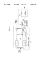
- FIG. 2 there is shown a block diagram of the channel quality estimator (CQE) 10 utilizing the 1-NEC scheme to estimate the Symbol Error Rate (SER), which is the ratio of number of symbols in error to the number of symbols transmitted.
- a received signal is coupled to a one symbol differential detector 12 (1DD) and a two symbol differential detector 14 (2DD).
- the detected signal outputs from the one symbol differential detector 12 and the two symbol detector 14 are coupled into an error detector 16 (ED).
- the error detector 16 detects the presence of an error based on the syndromes developed from the inputs and outputs an error signal.
- Summer 18 subtracts the error signal from the output of the one symbol differential detector 12 producing a corrected signal.
- the one symbol differential detector 12, the two symbol differential detector 14, the error detector 16 and the summer 18 comprise the 1-NEC system 20.
- the error signal is coupled to an accumulator (AC) 22.
- the accumulator 22 counts the number of symbol errors providing a symbol error count (SEC).
- the accumulator utilizes a summer 24 and a delay element 26, wherein the output of the summer 24 is coupled to the delay element 26, and the output of the delay element 26 and the error signal are coupled to the summer 24.
- the output of the summer 24 provides the symbol error count.
- divisor 28 an estimate of the symbol error rate 32 is obtained by dividing the symbol error count 28 by the number of symbols received. The number of symbols received per time slot is known a priori as defined in the NADC standard.
- FIG. 3 there is shown a block diagram of the channel quality estimator (CQE) utilizing the 2-NEC scheme to estimate the Symbol Error Rate (SER). Elements performing the same functions to those in FIG. 2 are assigned the same numbers in FIG. 3.
- a received signal is coupled to a one symbol differential detector 12 (1DD), a two symbol differential detector 14 (2DD) and a three symbol differential detector 30 (3DD).
- the detected signal outputs from the one symbol differential detector 12, the two symbol detector 14 and the three symbol differential detector 30 are coupled into an error detector 16 (ED).
- the error detector 16 detects the presence of an error based on the syndromes developed from the inputs and outputs an error signal.
- Summer 18 subtracts the error signal from the output of the one symbol differential detector 12 producing a corrected signal.
- the one symbol differential detector 12, the two symbol differential detector 14, the three symbol differential detector 30, the error detector 16 and the summer 18 comprise the 2-NEC system 20.
- the error signal is coupled to an accumulator (AC) 22.
- the accumulator 22 counts the number of symbol errors providing a symbol error count (SEC).
- the accumulator utilizes a summer 24 and a delay element 26, wherein the output of the summer 24 is coupled to the delay element 26, and the output of the delay element 26 and the error signal are coupled to the summer 24.
- the output of the summer 24 provides the symbol error count.
- divisor 28 an estimate of the symbol error rate 32 is obtained by dividing the symbol error count 28 by the number of symbols received. The number of symbols received per time slot is known a priori as defined in the NADC standard.
- FIG. 4 there is shown a block diagram of the channel quality estimator (CQE) generalized utilizing an (n-1)-NEC scheme to estimate the Symbol Error Rate (SER). Elements performing the same functions to those in FIG. 2 and FIG. 3 are assigned the same numbers in FIG. 2 and FIG. 3.
- a received signal is coupled to a one symbol differential detector 12 (1DD), a two symbol differential detector 14 (2DD), a three symbol differential detector 30 (3DD), on up to an n symbol differential detector 32 (nDD).
- the detected signal outputs from the one symbol differential detector 12, the two symbol detector 14, the three symbol differential detector 30, on up to the n symbol differential detector 32 are coupled into an error detector 16 (ED).
- ED error detector 16
- the error detector 16 detects the presence of an error based on the syndromes developed from the inputs and outputs an error signal.
- Summer 18 subtracts the error signal from the output of the one symbol differential detector 12 producing a corrected signal.
- the one symbol differential detector 12, the two symbol differential detector 14, the three symbol differential detector 30, on up to the n symbol differential detector 32, the error detector 16 and the summer 18 comprise the (n-1)-NEC system 20.
- the error signal is coupled to an accumulator (AC) 22.
- the accumulator 22 counts the number of symbol errors providing a symbol error count (SEC).
- the accumulator utilizes a summer 24 and a delay element 26, wherein the output of the summer 24 is coupled to the delay element 26, and the output of the delay element 26 and the error signal are coupled to the summer 24.
- the output of the summer 24 provides the symbol error count.
- divisor 28 an estimate of the symbol error rate 32 is obtained by dividing the symbol error count 28 by the number of symbols received. The number of symbols received per time slot is known a prior
- FIG. 5 there is shown a graph of the test results of the present invention on the NADC system in the presence of additive white Gaussian noise (AWGN) and flat fading.
- the SER is plotted as a function of Eb/No (bit-energy/noise density) in the AWGN channel obtained using 1-NEC CQE.
- the bit error rate (BER) of a conventional differential detector and the 1-NEC differential detector are also plotted. It can be seen that the SER estimate follows very closely the BER obtained using the differential detector.
- the SER and BER are proportional to each other.
- FIG. 6 there is shown a graph of the test results of the present invention of the SER obtained using 1-NEC CQE in a flat fading (doppler 80 Hz) channel condition which is typical of a cellular environment.
- the SER estimate follows the same trend as the BER of the conventional differential detector.
- FIG. 7 there is shown a graph of the SER estimate using 2-NEC CQE as a function of Eb/No in an AWGN channel.
- FIG. 8 there is shown a graph of the estimate of the SER in a flat fading (doppler 80 Hz) environment.
- the trend of the SER estimate obtained from the 1-NEC CQE follows closely the BER trend of a conventional differential detector in an AWGN channel, while the trend of the SER estimate obtained from 2-NEC CQE follows closely the BER of a conventional differential detector in a flat fading environment.
Landscapes
- Engineering & Computer Science (AREA)
- Quality & Reliability (AREA)
- Computer Networks & Wireless Communication (AREA)
- Signal Processing (AREA)
- Mobile Radio Communication Systems (AREA)
Abstract
Description
Claims (17)
Priority Applications (1)
| Application Number | Priority Date | Filing Date | Title |
|---|---|---|---|
| US08/846,633 US6094740A (en) | 1997-04-30 | 1997-04-30 | Channel quality estimator based on non-redundant error correction |
Applications Claiming Priority (1)
| Application Number | Priority Date | Filing Date | Title |
|---|---|---|---|
| US08/846,633 US6094740A (en) | 1997-04-30 | 1997-04-30 | Channel quality estimator based on non-redundant error correction |
Publications (1)
| Publication Number | Publication Date |
|---|---|
| US6094740A true US6094740A (en) | 2000-07-25 |
Family
ID=25298480
Family Applications (1)
| Application Number | Title | Priority Date | Filing Date |
|---|---|---|---|
| US08/846,633 Expired - Fee Related US6094740A (en) | 1997-04-30 | 1997-04-30 | Channel quality estimator based on non-redundant error correction |
Country Status (1)
| Country | Link |
|---|---|
| US (1) | US6094740A (en) |
Cited By (6)
| Publication number | Priority date | Publication date | Assignee | Title |
|---|---|---|---|---|
| US6215779B1 (en) * | 1998-09-22 | 2001-04-10 | Qualcomm Inc. | Distributed infrastructure for wireless data communications |
| US6553008B1 (en) * | 1998-01-19 | 2003-04-22 | Nec Corporation | Multidirectional time-division multiplexing wireless data communications system |
| US20050171994A1 (en) * | 2004-01-30 | 2005-08-04 | Broadcom Corporation | System for monitoring the quality of a communications channel with mirror receivers |
| US20050188284A1 (en) * | 2004-01-30 | 2005-08-25 | Broadcom Corporation | Method of monitoring the quality of a communications channel |
| US7062687B1 (en) * | 1999-07-12 | 2006-06-13 | International Business Machines Corporation | Apparatus and method for setting a data rate in a wireless communication system |
| US20080013511A1 (en) * | 1998-09-22 | 2008-01-17 | Bender Paul E | Distributed infrastructure for wireless data communications |
Citations (1)
| Publication number | Priority date | Publication date | Assignee | Title |
|---|---|---|---|---|
| US4128828A (en) * | 1976-09-28 | 1978-12-05 | Nippon Telegraph And Telephone Public Corp. | Differential detection systems with non-redundant error correction |
-
1997
- 1997-04-30 US US08/846,633 patent/US6094740A/en not_active Expired - Fee Related
Patent Citations (1)
| Publication number | Priority date | Publication date | Assignee | Title |
|---|---|---|---|---|
| US4128828A (en) * | 1976-09-28 | 1978-12-05 | Nippon Telegraph And Telephone Public Corp. | Differential detection systems with non-redundant error correction |
Non-Patent Citations (6)
| Title |
|---|
| Freebersyser, James et al., Non Redundant Error Correction of Uncoded M DPSK Using a Modified Viterbi Algorithm and a Sliding Block Non Coherent Multiple Symbol Detector, IEEE, 1994. * |
| Freebersyser, James et al., Non-Redundant Error Correction of Uncoded M-DPSK Using a Modified Viterbi Algorithm and a Sliding Block Non-Coherent Multiple-Symbol Detector, IEEE, 1994. |
| Wong et al., Nonredundant Error Correction analysis and Evaluation of differentially detected II/4 shift DQPSK system in a Combined CCI and AWGN Environment, Feb. 1992, IEEE. pp. 35 to 48. * |
| Wong et al., Nonredundant Error Correction DQPSK for the Aeronautical Satellite Channel, Jan. 1995, IEEE pp. 168 to 181. * |
| Wong et al., Nonredundant Error Correction DQPSK for the Aeronautical-Satellite Channel, Jan. 1995, IEEE pp. 168 to 181. |
| Yang et al., An Improved II/4 QPSK with Nonredundant Error Correction for Satellite Mobile Broadcasting, Mar. 1991, IEEE, pp. 9 to 16. * |
Cited By (12)
| Publication number | Priority date | Publication date | Assignee | Title |
|---|---|---|---|---|
| US6553008B1 (en) * | 1998-01-19 | 2003-04-22 | Nec Corporation | Multidirectional time-division multiplexing wireless data communications system |
| US6215779B1 (en) * | 1998-09-22 | 2001-04-10 | Qualcomm Inc. | Distributed infrastructure for wireless data communications |
| US20080013511A1 (en) * | 1998-09-22 | 2008-01-17 | Bender Paul E | Distributed infrastructure for wireless data communications |
| US7715356B2 (en) | 1998-09-22 | 2010-05-11 | Qualcomm Incorporated | Distributed infrastructure for wireless data communications |
| US20100220688A1 (en) * | 1998-09-22 | 2010-09-02 | Qualcomm Incorporated | Distributed infrastructure for wireless data communications |
| US8274948B2 (en) | 1998-09-22 | 2012-09-25 | Qualcomm Incorporated | Distributed infrastructure for wireless data communications |
| US7062687B1 (en) * | 1999-07-12 | 2006-06-13 | International Business Machines Corporation | Apparatus and method for setting a data rate in a wireless communication system |
| US20050171994A1 (en) * | 2004-01-30 | 2005-08-04 | Broadcom Corporation | System for monitoring the quality of a communications channel with mirror receivers |
| US20050188284A1 (en) * | 2004-01-30 | 2005-08-25 | Broadcom Corporation | Method of monitoring the quality of a communications channel |
| US7333537B2 (en) * | 2004-01-30 | 2008-02-19 | Broadcom Corporation | System for monitoring the quality of a communications channel with mirror receivers |
| US7339986B2 (en) | 2004-01-30 | 2008-03-04 | Broadcom Corporation | Method of monitoring the quality of a communications channel |
| US7702010B2 (en) | 2004-01-30 | 2010-04-20 | Broadcom Corporation | System for monitoring the quality of a communications channel with mirror receivers |
Similar Documents
| Publication | Publication Date | Title |
|---|---|---|
| Falconer et al. | Time division multiple access methods for wireless personal communications | |
| US6061549A (en) | Support of multiple modulation levels for a cellular traffic channel | |
| JP3966369B2 (en) | Forward traffic channel power control method and apparatus for CDMA wireless subscriber network system | |
| US5732328A (en) | Method for power control in wireless networks for communicating multiple information classes | |
| Moreira et al. | Diversity techniques for OFDM based WLAN systems. | |
| Esmailzadeh et al. | TDD-CDMA for the 4th generation of wireless communications | |
| US5909469A (en) | Link adaptation method for links using modulation schemes that have different symbol rates | |
| US6907063B2 (en) | Mobile station, a method of transmitting electronic information, and a communications system | |
| US10764006B2 (en) | Method and apparatus for generating pilot tone in orthogonal frequency division multiplexing access system, and method and apparatus for estimating channel using it | |
| EP1364472B1 (en) | Method, apparatus, and system for optimizing transmisson power and bit rate in multi-transmission scheme communication systems | |
| Brown et al. | A flexible modem structure for increased network capacity and multimedia transmission in GSM PCS | |
| US6314082B1 (en) | Broadcast network selection techniques for radiocommunication systems | |
| JP2001515306A (en) | Method of selecting a link protocol for a transparent data service in a digital communication system | |
| WO2000005912A1 (en) | Method of allocating resources and allocation scheme therefor | |
| KR20020026475A (en) | Code division multiple access system having improved pilot channels | |
| US5715240A (en) | Communication device capable of estimating signal quality without synchronization pattern | |
| EP0674451A2 (en) | A data transmission method, transmitter, and receiver | |
| US20030199275A1 (en) | Radio communication system, mobile radio communication apparatus and method therefor, fixed radio communication apparatus and method therefor, recording medium, and program | |
| EP1434381B1 (en) | Link adaptation process | |
| US6094740A (en) | Channel quality estimator based on non-redundant error correction | |
| US6370157B2 (en) | Automatic frequency control for a cellular base station | |
| JP2001168788A (en) | Wireless communication system and wireless communication device | |
| Toskala et al. | Cellular OFDM/CDMA downlink performance in the link and system levels | |
| EP1191719A2 (en) | Method and apparatus for signal quality estimation in a communication system | |
| Jhunjhunwala et al. | Wireless in Local Loop—Some Fundamentals |
Legal Events
| Date | Code | Title | Description |
|---|---|---|---|
| AS | Assignment |
Owner name: LUCENT TECHNOLOGIES, INC., NEW JERSEY Free format text: ASSIGNMENT OF ASSIGNORS INTEREST;ASSIGNORS:BOCCUZZI, JOSEPH;PETRUS, PAUL;REEL/FRAME:008956/0232;SIGNING DATES FROM 19971119 TO 19971222 |
|
| FEPP | Fee payment procedure |
Free format text: PAYOR NUMBER ASSIGNED (ORIGINAL EVENT CODE: ASPN); ENTITY STATUS OF PATENT OWNER: LARGE ENTITY |
|
| AS | Assignment |
Owner name: THE CHASE MANHATTAN BANK, AS COLLATERAL AGENT, TEX Free format text: CONDITIONAL ASSIGNMENT OF AND SECURITY INTEREST IN PATENT RIGHTS;ASSIGNOR:LUCENT TECHNOLOGIES INC. (DE CORPORATION);REEL/FRAME:011722/0048 Effective date: 20010222 |
|
| FEPP | Fee payment procedure |
Free format text: PAYOR NUMBER ASSIGNED (ORIGINAL EVENT CODE: ASPN); ENTITY STATUS OF PATENT OWNER: LARGE ENTITY Free format text: PAYER NUMBER DE-ASSIGNED (ORIGINAL EVENT CODE: RMPN); ENTITY STATUS OF PATENT OWNER: LARGE ENTITY |
|
| FPAY | Fee payment |
Year of fee payment: 4 |
|
| AS | Assignment |
Owner name: LUCENT TECHNOLOGIES INC., NEW JERSEY Free format text: TERMINATION AND RELEASE OF SECURITY INTEREST IN PATENT RIGHTS;ASSIGNOR:JPMORGAN CHASE BANK, N.A. (FORMERLY KNOWN AS THE CHASE MANHATTAN BANK), AS ADMINISTRATIVE AGENT;REEL/FRAME:018590/0047 Effective date: 20061130 |
|
| REMI | Maintenance fee reminder mailed | ||
| LAPS | Lapse for failure to pay maintenance fees | ||
| STCH | Information on status: patent discontinuation |
Free format text: PATENT EXPIRED DUE TO NONPAYMENT OF MAINTENANCE FEES UNDER 37 CFR 1.362 |
|
| FP | Lapsed due to failure to pay maintenance fee |
Effective date: 20080725 |