US6093122A - Hybrid spring for bicycle derailleurs - Google Patents
Hybrid spring for bicycle derailleurs Download PDFInfo
- Publication number
- US6093122A US6093122A US09/005,214 US521498A US6093122A US 6093122 A US6093122 A US 6093122A US 521498 A US521498 A US 521498A US 6093122 A US6093122 A US 6093122A
- Authority
- US
- United States
- Prior art keywords
- spring
- coil spring
- link mechanism
- axis
- bicycle derailleur
- Prior art date
- Legal status (The legal status is an assumption and is not a legal conclusion. Google has not performed a legal analysis and makes no representation as to the accuracy of the status listed.)
- Expired - Lifetime
Links
- 238000006073 displacement reaction Methods 0.000 claims description 10
- 238000000034 method Methods 0.000 claims 2
- 238000000926 separation method Methods 0.000 claims 2
- 238000000418 atomic force spectrum Methods 0.000 description 6
- 230000006835 compression Effects 0.000 description 6
- 238000007906 compression Methods 0.000 description 6
- 230000007423 decrease Effects 0.000 description 4
- 230000000694 effects Effects 0.000 description 4
- 239000013536 elastomeric material Substances 0.000 description 3
- 230000003247 decreasing effect Effects 0.000 description 2
- 239000000463 material Substances 0.000 description 2
- 239000000654 additive Substances 0.000 description 1
- 230000000996 additive effect Effects 0.000 description 1
- 238000011109 contamination Methods 0.000 description 1
- 230000001186 cumulative effect Effects 0.000 description 1
- 230000001747 exhibiting effect Effects 0.000 description 1
- 238000005461 lubrication Methods 0.000 description 1
- 238000004806 packaging method and process Methods 0.000 description 1
- 239000013589 supplement Substances 0.000 description 1
Images


Classifications
-
- B—PERFORMING OPERATIONS; TRANSPORTING
- B62—LAND VEHICLES FOR TRAVELLING OTHERWISE THAN ON RAILS
- B62M—RIDER PROPULSION OF WHEELED VEHICLES OR SLEDGES; POWERED PROPULSION OF SLEDGES OR SINGLE-TRACK CYCLES; TRANSMISSIONS SPECIALLY ADAPTED FOR SUCH VEHICLES
- B62M9/00—Transmissions characterised by use of an endless chain, belt, or the like
- B62M9/04—Transmissions characterised by use of an endless chain, belt, or the like of changeable ratio
- B62M9/06—Transmissions characterised by use of an endless chain, belt, or the like of changeable ratio using a single chain, belt, or the like
- B62M9/10—Transmissions characterised by use of an endless chain, belt, or the like of changeable ratio using a single chain, belt, or the like involving different-sized wheels, e.g. rear sprocket chain wheels selectively engaged by the chain, belt, or the like
- B62M9/12—Transmissions characterised by use of an endless chain, belt, or the like of changeable ratio using a single chain, belt, or the like involving different-sized wheels, e.g. rear sprocket chain wheels selectively engaged by the chain, belt, or the like the chain, belt, or the like being laterally shiftable, e.g. using a rear derailleur
- B62M9/121—Rear derailleurs
- B62M9/124—Mechanisms for shifting laterally
- B62M9/1248—Mechanisms for shifting laterally characterised by the use of biasing means, e.g. springs; Arrangements thereof
-
- B—PERFORMING OPERATIONS; TRANSPORTING
- B62—LAND VEHICLES FOR TRAVELLING OTHERWISE THAN ON RAILS
- B62M—RIDER PROPULSION OF WHEELED VEHICLES OR SLEDGES; POWERED PROPULSION OF SLEDGES OR SINGLE-TRACK CYCLES; TRANSMISSIONS SPECIALLY ADAPTED FOR SUCH VEHICLES
- B62M9/00—Transmissions characterised by use of an endless chain, belt, or the like
- B62M9/04—Transmissions characterised by use of an endless chain, belt, or the like of changeable ratio
- B62M9/06—Transmissions characterised by use of an endless chain, belt, or the like of changeable ratio using a single chain, belt, or the like
- B62M9/10—Transmissions characterised by use of an endless chain, belt, or the like of changeable ratio using a single chain, belt, or the like involving different-sized wheels, e.g. rear sprocket chain wheels selectively engaged by the chain, belt, or the like
- B62M9/12—Transmissions characterised by use of an endless chain, belt, or the like of changeable ratio using a single chain, belt, or the like involving different-sized wheels, e.g. rear sprocket chain wheels selectively engaged by the chain, belt, or the like the chain, belt, or the like being laterally shiftable, e.g. using a rear derailleur
- B62M9/121—Rear derailleurs
- B62M9/124—Mechanisms for shifting laterally
- B62M9/1242—Mechanisms for shifting laterally characterised by the linkage mechanisms
Definitions
- This invention relates to derailleur-type bicycle gear shifting devices. More particularly, it relates to spring biased derailleur-type shifting devices exhibiting a desired biasing force curve.
- Bicycle derailleurs are used to effect gear shifts by changing the position of a drive chain between the variable diameter sprockets of a multi-sprocket freewheel or crankset.
- the position of a chain on a sprocket of a freewheel or on a chainring of a crankset determines the gear ratio of the bicycle at which the rider must pedal.
- a derailleur includes a parallelogram link mechanism that is attached to a bicycle frame element at one end and to a chain guide at another end, the chain guide laterally urging the chain between the multiple sprockets or chainrings.
- a control cable is tied at one end to a shifter mounted proximate the rider's hand on the handlebar, or on the downtube of a bicycle frame and at the second end to the parallelogram.
- the parallelogram is typically spring biased in a given direction, requiring the rider to actuate the shifter and tension the control cable in order to deflect the parallelogram, and in turn urge the chain, in a direction opposite to the spring biased direction.
- FIG. 1 illustrates a parallelogram that is deflected from position (a) to position (b) by an actuation of a cable force F c against the biasing force of a coil return spring.
- the spring force increases; however, the moment arm over which it acts decreases from l a at undeflected position (a) to l b at deflected position (b).
- the spring force is increasing at a rate greater than the spring moment arm is decreasing producing an increasing biasing force F b .
- FIG. 2 illustrates the progression of biasing and spring forces and spring moment arm over the actuation range of a typical parallelogram biased by a coil spring.
- a rear derailleur is spring biased toward the smaller diameter or higher gear sprocket. Shifting to a lower gear by urging the chain toward the smaller sprocket requires a generally uniform biasing force, but biasing force tension falls off when approaching the largest sprocket or lowest gear where shifting can be most critical.
- the bicycle derailleur of the present invention includes a substantially parallelogram link mechanism displaceable over its range of motion by a biasing force, the biasing force working against a primary spring force resisting displacement of the derailleur for the full range of movement.
- a secondary spring force further resisting parallelogram displacement is introduced at an intermediate point to substantially eliminate the drop-off in the biasing force. The timed or staggered introduction of the secondary "booster" spring force ensures that a substantially constant biasing force can be achieved for the working range of derailleur movement.
- the spring assist is provided by an additional spring that "kicks in” at an appropriate time to level off the biasing force curve.
- separate springs provide separate spring forces to resist derailleur movement, the introduction of one spring force staggered with respect to the other, but nevertheless still cumulative.
- a single spring is acted upon by a secondary member to produce two spring forces.
- both spring forces are additive with one introduced later in the range of parallelogram movement to achieve a desired biasing force curve.
- the ends of two concentric coil springs are attached about diagonally opposed pivot points of the parallelogram. At least one end of one of the coil springs, however, is slidably connected to one of the pivots forming a gap between the pivot and the spring end the direction of the spring axis in an undeflected parallelogram. The gap spacing is then designed to properly time the introduction of the second spring force to achieve a substantially constant biasing force.
- the secondary spring force is produced by a torsion spring typically mounted about one of the parallelogram pivot points, the legs of the torsion spring extending to engage adjoining link members of the parallelogram.
- a torsion spring typically mounted about one of the parallelogram pivot points, the legs of the torsion spring extending to engage adjoining link members of the parallelogram.
- at least one leg of the torsion spring is spaced from its adjoining abutment surface located on one of the link members by a gap, the gap to be taken up during deflection of the parallelogram.
- an axial "lockout” member located coaxially about the coil spring loosely clasps individual spring coils at the upper and lower ends of the axial member.
- the slack in the direction of the spring axis between the axial member and the spring coils being taken up and causing the axial member to restrict further stretching of the spring segment circumscribed by the axial member.
- a secondary--and higher--spring rate is achieved by the single coil spring.
- an axial member formed of an elastomeric material can be used to produce a lower spring rate. Additional spring rates can also be achieved by varying the number of spring coils circumscribed by the axial member.
- a radial "lockout” member similarly restricts further extension of a segment of the coil spring, this time by preventing or cushioning further inward constriction of the spring coils as the coil spring is tensioned by the movement of the parallelogram.
- the radial member is suspended coaxially within the coil spring and is crushed by the natural inward constriction of the coils during extension of the spring along its axis. Again, by adjusting the elasticity of the radial member and its length, various higher secondary spring rates can be achieved with a single coil spring.
- opposed parallelogram axes are held apart by a coil spring under compression.
- the coil pitch is reduced.
- the coils having the reduced coil pitch reach a point where they abut each other, causing the compression spring to exhibit a secondary and higher spring force as a whole.
- an abutment member attached to on one of the link members forming the parallelogram or about one of the pivots, is urged against the coil spring during rotation of the parallelogram imparting a transverse force to the coil spring and laterally deflecting the coil spring.
- the application of a transverse load on the spring at an intermediate point of derailleur movement produces a secondary higher spring rate.
- a suitable biasing force can be achieved over the derailleur actuation range.
- the abutment can be slidably attached to a link member allowing adjustment of the amount of lateral deflection imparted to the coil spring.
- FIG. 1 is a schematic of the core elements making up a derailleur parallelogram in deflected and undeflected positions;
- FIG. 2 is a plot of the biasing and spring forces and spring moment arm with respect to rotation of a parallelogram
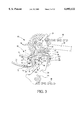
- FIG. 3 is an elevational view of a rear derailleur attached to a bicycle frame
- FIG. 4 is a detailed elevational view of the rear derailleur showing in particular the p-knuckle, b-knuckle, sideplates, and coil spring;
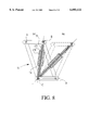
- FIG. 5 is a schematic of the parallelogram according to the invention in deflected and undeflected positions embodying a secondary torsion spring;
- FIG. 6 is a plot of the biasing force curve with respect to parallelogram deflection
- FIG. 7 is a schematic of the parallelogram according to the invention in deflected and undeflected positions embodying a secondary coaxial coil spring
- FIG. 8 is a schematic of the parallelogram according to the invention in deflected and undeflected positions embodying a secondary axial "lockout" member;
- FIG. 9 is a schematic of the parallelogram according to the invention in deflected and undeflected positions embodying a secondary radial "lockout" member;
- FIG. 10 is a schematic of the parallelogram according to the invention in deflected and undeflected positions embodying a secondary abutment member
- FIG. 11 is a schematic of the parallelogram according to the invention in deflected and undeflected positions embodying a primary compressive coil spring
- FIG. 12 is a schematic of the parallelogram according to the invention in deflected and undeflected positions embodying an attachment point for one end of the primary spring proximate a parallelogram pivot.
- the bicycle derailleur of the present invention substantially eliminates or reduces the described disadvantages of prior art shifting systems. According to one aspect of the invention, by staggering or timing the introduction of the working range of multiple spring elements in a derailleur having a parallelogram link mechanism, a substantially constant biasing force is achieved over the actuation range of a derailleur.
- a bicycle derailleur indicated generally at 50 is attached by a bolt 54 to a dropout member 52 of a bicycle frame 18.
- Derailleur 50 includes a parallelogram link mechanism 51 comprising a base member 56 (termed the “b-knuckle”) attached at one end to the bicycle frame 18 at dropout 52, an end member 88 (termed the “p-knuckle”) connected to a chain guide 110, an inboard sideplate 66 pivotally attached to b-knuckle 56 at pivot D and to p-knuckle 88 at pivot B, and an outboard sideplate 64 pivotally attached to b-knuckle 56 at pivot C and to p-knuckle 88 at pivot A.
- the chain guide 110 laterally urges a drive chain 48 between multiple sprockets 46 of a freewheel 44 at the rear wheel of the bicycle or between multiple chainrings of a crankset at the front derailleur (not shown) to effect gear shifts.
- Control cable 34 shown attached at one end to the outboard sideplate 64 at cable clamp 80, is attached at its other end to a rider-actuated shifter (not shown).
- FIG. 4 is a detailed elevational view of the rear derailleur showing in particular the p-knuckle 88, the b-knuckle 56 and sideplates 64, 66 and a coil spring 77 connected about and drawing together pivot points B and C and biasing derailleur 50 in an outboard direction away from the bicycle frame 18.
- parallelogram 51 is in its undeflected or outboard-most position, requiring the input of a biasing force F b in order to overcome the biasing force to deflect or rotate the parallelogram 51 to its inboard most position.
- FIG. 5 schematically illustrates parallelogram 51 in undeflected and deflected positions (a) and (b), respectively. Furthermore, a torsion spring 150 is shown in undeflected position (a) wrapped about pivot A and loosely engaging p-knuckle 88 at peg 152 with a first leg 158, a second leg 156 of the torsion spring not contacting peg 154 of sideplate 64. Accordingly, at the onset of parallelogram deflection, coil spring 77 is tensioned but torsion spring 150 is not.
- the force in coil spring 77 increases; however, the moment arm over which it acts decreases from l a at undeflected position (a) to l b at deflected position (b).
- the force in coil spring 77 increases at a rate greater than the rate at which the spring 77 moment arm is decreasing, producing an increasing biasing force F b that is required to be exerted by the rider (as depicted by line segment w in FIG. 6 to overcome the biasing force).
- the spring 77 moment arm progressively decreases at a rate greater than that of the still-increasing force in coil spring 77, producing a drop-off in the biasing force (as depicted by line segment y in FIG. 6). It is at this point in the actuation range of parallelogram 51 that torsional spring 150 is engaged or "kicks in” to provide an additional increment of spring assist to produce a substantially constant biasing force (as depicted by line segment x in FIG. 6).
- Torsion spring 150 becomes engaged when the gap existing between leg 156 of the torsional spring and peg 154 of sideplate 64 is taken up during deflection of the parallelogram 51 and both legs 156 and 158 of the torsional spring are pried open by pegs 154 and 152, respectively.
- FIGS. 7 through 12 likewise schematically illustrate the range of movement of parallelogram 51, the parallelogram in each FIGURE embodying various spring combinations to achieve a desired biasing force curve.
- FIG. 7 depicts an additional embodiment of the invention employing a second coil spring 160 having a first end 164 connected about pivot B and a second end 162 slidably connected about pivot B along the spring axis.
- a gap is formed between spring end 162 and pivot C in the direction of the spring axis.
- primary coil spring 77 is tensioned and secondary coil spring 160 is not.
- deflected position (b) both springs are tensioned.
- the gap spacing is designed to properly time the introduction of the force of spring 160 to supplement the force of spring 77 to achieve the desired biasing force over the derailleur range of movement.
- FIG. 8 depicts an additional embodiment of the invention employing a rigid axial "lockout" member 170 located coaxially about coil spring 77 and having upper and lower ends 172 and 174, respectively, the ends loosely clasping individual, spaced-apart coils of spring 77.
- spring 77 At undeflected position (a), spring 77 is tensioned but axial member 170 is not.
- FIG. 9 depicts an additional embodiment of the invention employing a radial "lockout” member 180 that likewise restricts further extension of a segment of the coil spring.
- Radial member 180 is suspended coaxially within the coil spring 77 and is crushed by the natural inward constriction of the spring coils of a segment of spring 77 during extension of spring 77 along its spring axis, as shown in deflected position (b). At undeflected position (a), radial element 180 is not in contact with the inner surface of the coils of spring 77.
- FIG. 10 depicts an additional embodiment of the invention employing an abutment member 190 shown attached to sideplate 64 with bolt 192.
- abutment member 190 At undeflected parallelogram position (a), abutment member 190 is located adjacent to but is not in contact with spring 77.
- abutment member At deflected parallelogram position (b), abutment member abuts spring 77, forcing the spring to displace laterally and forming two spring axes a1 and a2.
- the application of a transverse load on the spring 77 by abutment member 190 produces a secondary and higher spring rate.
- a suitable biasing force can be achieved over the derailleur actuation range.
- the abutment member 190 can be slidably attached to sideplate 64 or any of the other link members 56, 66 or 88 or attached about one of the pivots A, B, C, or D.
- FIG. 11 depicts an additional embodiment of the invention employing a compression coil spring 200 connected about pivots A and D and coaxially encased within cylindrical housing 202 to prevent lateral buckling of the compression spring 200 under load.
- a segment z of compression spring 200 is formed with reduced pitch coils.
- spring 200 In undeflected parallelogram position (a), spring 200 is not under compression or tension loading and the coils forming segment z of spring 200, albeit of reduced pitch, are not in contact with each other.
- deflected position (b) the coils forming segment z are fully compressed.
- FIG. 12 depicts an additional embodiment of the invention employing a conventional coil spring 77 having a first end 206 attached to a peg 208 on link member 56 and a second end connected about pivot B.
- a conventional coil spring 77 having a first end 206 attached to a peg 208 on link member 56 and a second end connected about pivot B.
- various pivot-to-pivot, pivot-to-link member, and link member-to-link member attachment points for the spring ends will vary the orientation or slope of the standard spring curve shown in FIG. 2. Accordingly, various spring end attachment points can be used in combination with the various spring embodiments described above to achieve a desired biasing force curve.
Landscapes
- Engineering & Computer Science (AREA)
- Chemical & Material Sciences (AREA)
- Combustion & Propulsion (AREA)
- Transportation (AREA)
- Mechanical Engineering (AREA)
- Vibration Dampers (AREA)
Abstract
Description
Claims (36)
Priority Applications (1)
| Application Number | Priority Date | Filing Date | Title |
|---|---|---|---|
| US09/005,214 US6093122A (en) | 1998-01-09 | 1998-01-09 | Hybrid spring for bicycle derailleurs |
Applications Claiming Priority (1)
| Application Number | Priority Date | Filing Date | Title |
|---|---|---|---|
| US09/005,214 US6093122A (en) | 1998-01-09 | 1998-01-09 | Hybrid spring for bicycle derailleurs |
Publications (1)
| Publication Number | Publication Date |
|---|---|
| US6093122A true US6093122A (en) | 2000-07-25 |
Family
ID=21714746
Family Applications (1)
| Application Number | Title | Priority Date | Filing Date |
|---|---|---|---|
| US09/005,214 Expired - Lifetime US6093122A (en) | 1998-01-09 | 1998-01-09 | Hybrid spring for bicycle derailleurs |
Country Status (1)
| Country | Link |
|---|---|
| US (1) | US6093122A (en) |
Cited By (15)
| Publication number | Priority date | Publication date | Assignee | Title |
|---|---|---|---|---|
| US6726587B2 (en) | 2001-10-19 | 2004-04-27 | Shimano, Inc. | Adjustable bicycle derailleur |
| US20050288139A1 (en) * | 2004-06-23 | 2005-12-29 | Shimano Inc. | Front derailleur for bicycle |
| US20060135301A1 (en) * | 2004-12-20 | 2006-06-22 | Shimano Inc. | Rear derailleur for bicycle |
| US20080026891A1 (en) * | 2006-07-31 | 2008-01-31 | Shimano Inc. | Bicycle rear derailleur |
| US20130072333A1 (en) * | 2011-09-21 | 2013-03-21 | Shimano Inc. | Bicycle front derailleur |
| US20130079184A1 (en) * | 2011-09-27 | 2013-03-28 | Shimano Inc. | Bicycle rear derailleur |
| US20150094177A1 (en) * | 2013-09-30 | 2015-04-02 | Shimano Inc. | Derailleur |
| US20150094178A1 (en) * | 2013-09-30 | 2015-04-02 | Shimano Inc. | Derailleur |
| US9033833B2 (en) | 2011-01-28 | 2015-05-19 | Paha Designs, Llc | Gear transmission and derailleur system |
| DE102015213214A1 (en) | 2014-09-08 | 2016-03-10 | Shimano Inc. | Front bike derailleur |
| US9327792B2 (en) | 2011-01-28 | 2016-05-03 | Paha Designs, Llc | Gear transmission and derailleur system |
| US20160167740A1 (en) * | 2014-12-10 | 2016-06-16 | Yeti Cycling, Llc | Linear derailleur mechanism |
| DE102015010311A1 (en) * | 2015-08-06 | 2017-02-09 | Sram Deutschland Gmbh | Front derailleur device for a bicycle chain transmission |
| US10207772B2 (en) | 2011-01-28 | 2019-02-19 | Paha Designs, Llc | Gear transmission and derailleur system |
| US20230002006A1 (en) * | 2021-06-30 | 2023-01-05 | Shimano (Singapore) Pte. Ltd. | Derailleur for human-powered vehicle |
Citations (5)
| Publication number | Priority date | Publication date | Assignee | Title |
|---|---|---|---|---|
| US5518456A (en) * | 1993-11-30 | 1996-05-21 | Shimano, Inc. | Bicycle derailleur |
| US5660407A (en) * | 1995-08-28 | 1997-08-26 | Adams; Joseph Scott | Auxiliary chain tension system for bicycles |
| US5695421A (en) * | 1996-02-21 | 1997-12-09 | Shimano Inc. | Elastomer coated coil spring and chain derailleur employing same |
| US5860880A (en) * | 1996-11-21 | 1999-01-19 | Shimano, Inc. | Low normal bicycle derailleur which allows lateral movement of the chain guide toward the rear wheel in response to a force directed laterally towards the rear wheel |
| US5897451A (en) * | 1997-04-29 | 1999-04-27 | Shimano, Inc. | Bicycle derailleur having operating forces disposed on opposite sides of a link pivot |
-
1998
- 1998-01-09 US US09/005,214 patent/US6093122A/en not_active Expired - Lifetime
Patent Citations (5)
| Publication number | Priority date | Publication date | Assignee | Title |
|---|---|---|---|---|
| US5518456A (en) * | 1993-11-30 | 1996-05-21 | Shimano, Inc. | Bicycle derailleur |
| US5660407A (en) * | 1995-08-28 | 1997-08-26 | Adams; Joseph Scott | Auxiliary chain tension system for bicycles |
| US5695421A (en) * | 1996-02-21 | 1997-12-09 | Shimano Inc. | Elastomer coated coil spring and chain derailleur employing same |
| US5860880A (en) * | 1996-11-21 | 1999-01-19 | Shimano, Inc. | Low normal bicycle derailleur which allows lateral movement of the chain guide toward the rear wheel in response to a force directed laterally towards the rear wheel |
| US5897451A (en) * | 1997-04-29 | 1999-04-27 | Shimano, Inc. | Bicycle derailleur having operating forces disposed on opposite sides of a link pivot |
Cited By (41)
| Publication number | Priority date | Publication date | Assignee | Title |
|---|---|---|---|---|
| US6726587B2 (en) | 2001-10-19 | 2004-04-27 | Shimano, Inc. | Adjustable bicycle derailleur |
| US20050288139A1 (en) * | 2004-06-23 | 2005-12-29 | Shimano Inc. | Front derailleur for bicycle |
| US7762916B2 (en) * | 2004-06-23 | 2010-07-27 | Shimano Inc. | Front derailleur for bicycle |
| US20060135301A1 (en) * | 2004-12-20 | 2006-06-22 | Shimano Inc. | Rear derailleur for bicycle |
| EP1671881A3 (en) * | 2004-12-20 | 2007-03-07 | Shimano Inc. | Bicycle rear derailleur |
| US7527571B2 (en) * | 2004-12-20 | 2009-05-05 | Shimano Inc. | Rear derailleur for bicycle |
| US20080026891A1 (en) * | 2006-07-31 | 2008-01-31 | Shimano Inc. | Bicycle rear derailleur |
| US9327792B2 (en) | 2011-01-28 | 2016-05-03 | Paha Designs, Llc | Gear transmission and derailleur system |
| US9033833B2 (en) | 2011-01-28 | 2015-05-19 | Paha Designs, Llc | Gear transmission and derailleur system |
| US10207772B2 (en) | 2011-01-28 | 2019-02-19 | Paha Designs, Llc | Gear transmission and derailleur system |
| EP2572972A1 (en) | 2011-09-21 | 2013-03-27 | Shimano Inc. | Bicycle front derailleur |
| CN103010396A (en) * | 2011-09-21 | 2013-04-03 | 株式会社岛野 | Bicycle front derailleur |
| US8678963B2 (en) * | 2011-09-21 | 2014-03-25 | Shimano Inc. | Bicycle front derailleur |
| CN103010396B (en) * | 2011-09-21 | 2014-10-29 | 株式会社岛野 | Bicycle front derailleur |
| EP2572972B1 (en) * | 2011-09-21 | 2014-11-19 | Shimano Inc. | Bicycle front derailleur |
| US20130072333A1 (en) * | 2011-09-21 | 2013-03-21 | Shimano Inc. | Bicycle front derailleur |
| US9150281B2 (en) * | 2011-09-27 | 2015-10-06 | Shimano Inc. | Bicycle rear derailleur |
| EP2574539A3 (en) * | 2011-09-27 | 2015-04-01 | Shimano Inc. | Bicycle rear derailleur |
| CN103010394B (en) * | 2011-09-27 | 2014-12-24 | 株式会社岛野 | Bicycle rear derailleur |
| CN103010394A (en) * | 2011-09-27 | 2013-04-03 | 株式会社岛野 | Bicycle rear derailleur |
| US20130079184A1 (en) * | 2011-09-27 | 2013-03-28 | Shimano Inc. | Bicycle rear derailleur |
| US20150094177A1 (en) * | 2013-09-30 | 2015-04-02 | Shimano Inc. | Derailleur |
| US20150094178A1 (en) * | 2013-09-30 | 2015-04-02 | Shimano Inc. | Derailleur |
| US9156524B2 (en) * | 2013-09-30 | 2015-10-13 | Shimano Inc. | Derailleur |
| US9248885B2 (en) * | 2013-09-30 | 2016-02-02 | Shimano Inc. | Derailleur |
| DE102015213214A1 (en) | 2014-09-08 | 2016-03-10 | Shimano Inc. | Front bike derailleur |
| US20160068225A1 (en) * | 2014-09-08 | 2016-03-10 | Shimano Inc. | Bicycle front derailleur |
| DE102015213214B4 (en) | 2014-09-08 | 2023-06-07 | Shimano Inc. | Bicycle front derailleur |
| US9457871B2 (en) * | 2014-09-08 | 2016-10-04 | Shimano Inc. | Bicycle front derailleur |
| US10011325B2 (en) * | 2014-12-10 | 2018-07-03 | Yeti Cycling, Llc | Linear derailleur mechanism |
| US20180304967A1 (en) * | 2014-12-10 | 2018-10-25 | Yeti Cycling, Llc | Linear derailleur mechanism |
| US10894575B2 (en) * | 2014-12-10 | 2021-01-19 | Yeti Design, Llc | Linear derailleur mechanism |
| US20210171157A1 (en) * | 2014-12-10 | 2021-06-10 | Yeti Design, Llc | Linear derailleur mechanism |
| US20160167740A1 (en) * | 2014-12-10 | 2016-06-16 | Yeti Cycling, Llc | Linear derailleur mechanism |
| US11679838B2 (en) * | 2014-12-10 | 2023-06-20 | Yeti Design, Llc | Linear derailleur mechanism |
| US20240002015A1 (en) * | 2014-12-10 | 2024-01-04 | Yeti Design, Llc | Linear derailleur mechanism |
| US10106224B2 (en) * | 2015-08-06 | 2018-10-23 | Sram Deutschland, Gmbh | Front derailleur device for a bicycle chain shift |
| DE102015010311A1 (en) * | 2015-08-06 | 2017-02-09 | Sram Deutschland Gmbh | Front derailleur device for a bicycle chain transmission |
| US20230002006A1 (en) * | 2021-06-30 | 2023-01-05 | Shimano (Singapore) Pte. Ltd. | Derailleur for human-powered vehicle |
| US12240562B2 (en) * | 2021-06-30 | 2025-03-04 | Shimano (Singapore) Pte. Ltd. | Derailleur for human-powered vehicle |
| US20250171108A1 (en) * | 2021-06-30 | 2025-05-29 | Shimano (Singapore) Pte. Ltd. | Derailleur for human-powered vehicle |
Similar Documents
| Publication | Publication Date | Title |
|---|---|---|
| US6093122A (en) | Hybrid spring for bicycle derailleurs | |
| US5518456A (en) | Bicycle derailleur | |
| EP0850829B1 (en) | Rear derailleur for a bicycle | |
| US5104358A (en) | Bicycle front derailleur | |
| US4599079A (en) | Automatic derailleur shifter | |
| EP1415901B1 (en) | Bicycle derailleur with protective support | |
| US4938733A (en) | Bicycle gear shifting method and apparatus | |
| DE69510644T2 (en) | Front gear shift with independent, movable chain guide | |
| DE69416956T2 (en) | Rear gear shift for bicycle | |
| US8303443B2 (en) | Six link front derailleur | |
| EP0757952A1 (en) | Front derailleur for a bicycle | |
| EP0036317A2 (en) | Cycle derailleur | |
| EP2578487B1 (en) | Bicycle front derailleur with a variable actuation ratio | |
| EP1935774A1 (en) | Bicycle rear derailleur | |
| US3847028A (en) | Leaf spring biased derailleur arrangement | |
| US20060194660A1 (en) | Bicycle derailleur with a motion limiting structure | |
| US4183255A (en) | Bicycle with derailleur arrangement | |
| WO1998003805A1 (en) | Linear derailleur | |
| EP0020092B1 (en) | Cycle derailleur | |
| US4469479A (en) | Bicycle derailleur | |
| US5779580A (en) | Front bicycle derailleur | |
| US5865698A (en) | Rear derailleur for use in bicycles | |
| DE3511702A1 (en) | FRONT THREE-SPEED FRONT DERAILLEUR | |
| DE69018083T2 (en) | COMPENSATING DEVICE FOR AN ENDLESS FUEL. | |
| US4343613A (en) | Derailler system |
Legal Events
| Date | Code | Title | Description |
|---|---|---|---|
| AS | Assignment |
Owner name: SRAM CORPORATION, ILLINOIS Free format text: ASSIGNMENT OF ASSIGNORS INTEREST;ASSIGNORS:MCLAUGHLIN, SCOTT A.;JORDAN, BRIAN T.;WESLING, KEVIN F.;AND OTHERS;REEL/FRAME:009118/0324 Effective date: 19980408 |
|
| STCF | Information on status: patent grant |
Free format text: PATENTED CASE |
|
| AS | Assignment |
Owner name: BANK OF AMERICA, N.A., AS AGENT, A NATIONAL BANKIN Free format text: SECURITY AGREEMENT;ASSIGNOR:SRAM CORPORATION, A CORPORATION OF ILLINOIS;REEL/FRAME:011325/0409 Effective date: 20001005 |
|
| AS | Assignment |
Owner name: BANK OF AMERICA, N.A., AS AGENT, ILLINOIS Free format text: CORRECTIVE ASSIGNMENT TO CORRECT THE RECEIVING PARTY'S ADDRESS, PREVIOUSLY RECORDED AT REEL 011325 FRAME 0409;ASSIGNOR:SRAM CORPORATION;REEL/FRAME:011828/0135 Effective date: 20001005 |
|
| FPAY | Fee payment |
Year of fee payment: 4 |
|
| AS | Assignment |
Owner name: SRAM CORPORATION, ILLINOIS Free format text: INTELLECTUAL PROPERTY RELEASE;ASSIGNOR:LASALLE BANK, NATIONAL ASSOCIATION;REEL/FRAME:020105/0325 Effective date: 20071105 |
|
| AS | Assignment |
Owner name: JPMORGAN CHASE BANK N.A., AS AGENT, ILLINOIS Free format text: SECURITY INTEREST;ASSIGNOR:SRAM CORPORATION;REEL/FRAME:020112/0544 Effective date: 20071105 Owner name: JPMORGAN CHASE BANK N.A., AS AGENT,ILLINOIS Free format text: SECURITY INTEREST;ASSIGNOR:SRAM CORPORATION;REEL/FRAME:020112/0544 Effective date: 20071105 |
|
| FPAY | Fee payment |
Year of fee payment: 8 |
|
| AS | Assignment |
Owner name: SRAM CORPORATION, ILLINOIS Free format text: RELEASE BY SECURED PARTY;ASSIGNOR:JPMORGAN CHASE BANK, N.A., AS COLLATERAL AGENT;REEL/FRAME:021603/0759 Effective date: 20080930 Owner name: SRAM, LLC, ILLINOIS Free format text: MERGER;ASSIGNOR:SRAM CORPORATION;REEL/FRAME:021617/0263 Effective date: 20080930 Owner name: SRAM, LLC,ILLINOIS Free format text: MERGER;ASSIGNOR:SRAM CORPORATION;REEL/FRAME:021617/0263 Effective date: 20080930 Owner name: SRAM CORPORATION,ILLINOIS Free format text: RELEASE BY SECURED PARTY;ASSIGNOR:JPMORGAN CHASE BANK, N.A., AS COLLATERAL AGENT;REEL/FRAME:021603/0759 Effective date: 20080930 |
|
| AS | Assignment |
Owner name: GENERAL ELECTRIC CAPITAL CORPORATION, AS ADMINISTR Free format text: SECURITY AGREEMENT;ASSIGNOR:SRAM, LLC;REEL/FRAME:021630/0135 Effective date: 20080930 |
|
| AS | Assignment |
Owner name: SRAM, LLC, ILLINOIS Free format text: RELEASE OF SECURITY INTEREST IN INTELLECTUAL PROPERTY COLLATERAL;ASSIGNOR:GENERAL ELECTRIC CAPITAL CORPORATION, AS ADMINISTRATIVE AGENT;REEL/FRAME:026533/0452 Effective date: 20110607 |
|
| AS | Assignment |
Owner name: JPMORGAN CHASE BANK, N.A., AS ADMINISTRATIVE AGENT Free format text: FIRST LIEN PATENT SECURITY AGREEMENT;ASSIGNORS:COMPOSITECH;SRAM LLC;REEL/FRAME:026856/0464 Effective date: 20110607 Owner name: JPMORGAN CHASE BANK, N.A. AS ADMINISTRATIVE AGENT, Free format text: SECOND LIEN PATENT SECURITY AGREEMENT;ASSIGNORS:COMPOSITECH;SRAM LLC;REEL/FRAME:026869/0309 Effective date: 20110607 |
|
| FPAY | Fee payment |
Year of fee payment: 12 |
|
| AS | Assignment |
Owner name: COMPOSITECH, INC., ILLINOIS Free format text: RELEASE BY SECURED PARTY;ASSIGNOR:JPMORGAN CHASE BANK, N.A., AS ADMINISTRATIVE AGENT;REEL/FRAME:030248/0914 Effective date: 20130417 Owner name: SRAM, LLC, ILLINOIS Free format text: RELEASE BY SECURED PARTY;ASSIGNOR:JPMORGAN CHASE BANK, N.A., AS ADMINISTRATIVE AGENT;REEL/FRAME:030248/0914 Effective date: 20130417 |