US6092509A - Accumulator type fuel injection system - Google Patents
Accumulator type fuel injection system Download PDFInfo
- Publication number
- US6092509A US6092509A US09/443,009 US44300999A US6092509A US 6092509 A US6092509 A US 6092509A US 44300999 A US44300999 A US 44300999A US 6092509 A US6092509 A US 6092509A
- Authority
- US
- United States
- Prior art keywords
- fuel
- pressure
- accumulator
- control valve
- fuel injection
- Prior art date
- Legal status (The legal status is an assumption and is not a legal conclusion. Google has not performed a legal analysis and makes no representation as to the accuracy of the status listed.)
- Expired - Fee Related
Links
Images


Classifications
-
- F—MECHANICAL ENGINEERING; LIGHTING; HEATING; WEAPONS; BLASTING
- F02—COMBUSTION ENGINES; HOT-GAS OR COMBUSTION-PRODUCT ENGINE PLANTS
- F02D—CONTROLLING COMBUSTION ENGINES
- F02D41/00—Electrical control of supply of combustible mixture or its constituents
- F02D41/30—Controlling fuel injection
- F02D41/38—Controlling fuel injection of the high pressure type
- F02D41/40—Controlling fuel injection of the high pressure type with means for controlling injection timing or duration
- F02D41/401—Controlling injection timing
-
- F—MECHANICAL ENGINEERING; LIGHTING; HEATING; WEAPONS; BLASTING
- F02—COMBUSTION ENGINES; HOT-GAS OR COMBUSTION-PRODUCT ENGINE PLANTS
- F02D—CONTROLLING COMBUSTION ENGINES
- F02D41/00—Electrical control of supply of combustible mixture or its constituents
- F02D41/30—Controlling fuel injection
- F02D41/38—Controlling fuel injection of the high pressure type
- F02D41/3809—Common rail control systems
- F02D41/3827—Common rail control systems for diesel engines
-
- F—MECHANICAL ENGINEERING; LIGHTING; HEATING; WEAPONS; BLASTING
- F02—COMBUSTION ENGINES; HOT-GAS OR COMBUSTION-PRODUCT ENGINE PLANTS
- F02D—CONTROLLING COMBUSTION ENGINES
- F02D41/00—Electrical control of supply of combustible mixture or its constituents
- F02D41/30—Controlling fuel injection
- F02D41/38—Controlling fuel injection of the high pressure type
- F02D41/3809—Common rail control systems
- F02D41/3836—Controlling the fuel pressure
-
- F—MECHANICAL ENGINEERING; LIGHTING; HEATING; WEAPONS; BLASTING
- F02—COMBUSTION ENGINES; HOT-GAS OR COMBUSTION-PRODUCT ENGINE PLANTS
- F02M—SUPPLYING COMBUSTION ENGINES IN GENERAL WITH COMBUSTIBLE MIXTURES OR CONSTITUENTS THEREOF
- F02M47/00—Fuel-injection apparatus operated cyclically with fuel-injection valves actuated by fluid pressure
- F02M47/02—Fuel-injection apparatus operated cyclically with fuel-injection valves actuated by fluid pressure of accumulator-injector type, i.e. having fuel pressure of accumulator tending to open, and fuel pressure in other chamber tending to close, injection valves and having means for periodically releasing that closing pressure
- F02M47/027—Electrically actuated valves draining the chamber to release the closing pressure
-
- F—MECHANICAL ENGINEERING; LIGHTING; HEATING; WEAPONS; BLASTING
- F02—COMBUSTION ENGINES; HOT-GAS OR COMBUSTION-PRODUCT ENGINE PLANTS
- F02D—CONTROLLING COMBUSTION ENGINES
- F02D41/00—Electrical control of supply of combustible mixture or its constituents
- F02D41/30—Controlling fuel injection
- F02D41/38—Controlling fuel injection of the high pressure type
- F02D41/3809—Common rail control systems
- F02D2041/3881—Common rail control systems with multiple common rails, e.g. one rail per cylinder bank, or a high pressure rail and a low pressure rail
-
- F—MECHANICAL ENGINEERING; LIGHTING; HEATING; WEAPONS; BLASTING
- F02—COMBUSTION ENGINES; HOT-GAS OR COMBUSTION-PRODUCT ENGINE PLANTS
- F02D—CONTROLLING COMBUSTION ENGINES
- F02D41/00—Electrical control of supply of combustible mixture or its constituents
- F02D41/30—Controlling fuel injection
- F02D41/38—Controlling fuel injection of the high pressure type
- F02D2041/389—Controlling fuel injection of the high pressure type for injecting directly into the cylinder
-
- F—MECHANICAL ENGINEERING; LIGHTING; HEATING; WEAPONS; BLASTING
- F02—COMBUSTION ENGINES; HOT-GAS OR COMBUSTION-PRODUCT ENGINE PLANTS
- F02D—CONTROLLING COMBUSTION ENGINES
- F02D2200/00—Input parameters for engine control
- F02D2200/02—Input parameters for engine control the parameters being related to the engine
- F02D2200/06—Fuel or fuel supply system parameters
- F02D2200/0602—Fuel pressure
-
- Y—GENERAL TAGGING OF NEW TECHNOLOGICAL DEVELOPMENTS; GENERAL TAGGING OF CROSS-SECTIONAL TECHNOLOGIES SPANNING OVER SEVERAL SECTIONS OF THE IPC; TECHNICAL SUBJECTS COVERED BY FORMER USPC CROSS-REFERENCE ART COLLECTIONS [XRACs] AND DIGESTS
- Y02—TECHNOLOGIES OR APPLICATIONS FOR MITIGATION OR ADAPTATION AGAINST CLIMATE CHANGE
- Y02T—CLIMATE CHANGE MITIGATION TECHNOLOGIES RELATED TO TRANSPORTATION
- Y02T10/00—Road transport of goods or passengers
- Y02T10/10—Internal combustion engine [ICE] based vehicles
- Y02T10/40—Engine management systems
Definitions
- This invention relates to an accumulator type fuel injection system.
- An accumulator type fuel injection system which is adapted to stably supply a high-pressure fuel stored in an accumulator to each cylinder of a diesel engine, and in a broader operational range.
- a fuel injection rate immediately after the starting of fuel injection is excessively high in such a fuel injection system, sudden explosion combustion is carried out in an initial stage of combustion. Consequently, not only the noise of operation of the engine but also the NOx content of an exhaust gas increases.
- an accumulator type fuel injection system adapted to inject a fuel at a lower fuel injection rate in an initial stage of each fuel injection cycle.
- the fuel injection system relating to this proposal is provided with, for example, a low-pressure accumulator adapted to store a low-pressure fuel therein, a high-pressure accumulator adapted to store a high-pressure fuel therein, a change-over valve communicated selectively with the low-pressure accumulator or high-pressure accumulator with an injector (fuel injection nozzle) to switch an injection rate, and a switch valve adapted to communicate and shut off a control chamber of the injector and a fuel tank with and from each other and thereby control the injection time.
- an accumulator type fuel injection system adapted to obtain low-pressure and high-pressure fuels by using low-pressure and high-pressure pumps driven by an engine
- an accumulator type fuel injection system adapted to obtain a high-pressure fuel by a high-pressure pump, and a low-pressure fuel by regulating the pressure of the high-pressure fuel introduced into a low-pressure accumulator
- a fuel passage connecting a change-over valve and an injector together is filled with a low-pressure fuel by closing, for example, an injection time controlling switch valve and an injection rate switching change-over valve, and the low-pressure fuel is supplied to a control chamber of the injector communicating with the fuel passage to keep the injector closed.
- the switch valve When the injection starting time comes, the switch valve is opened to discharge the low-pressure fuel in the control chamber to a fuel tank, whereby the injector is opened to carry out initial low-pressure injection (which will hereinafter be referred to as low-pressure injection).
- the change-over valve When a low-pressure injection period passes, the change-over valve is opened to inject the high-pressure fuel, which is supplied from the high-pressure accumulator, from a nozzle and carry out main high-pressure injection (which will hereinafter be referred to as high-pressure injection).
- the change-over valve When the injection finishing time has comes, the change-over valve is closed. In the low-pressure accumulator, the pressure of the high-pressure fuel which has flowed from the fuel passage thereinto is regulated to obtain a low-pressure fuel.
- the target pressures of the high-pressure fuel in the high-pressure accumulator and the low-pressure fuel in the low-pressure accumulator are regulated variably in accordance with the operating condition of the engine, and low-pressure injection and high-pressure injection which suit the operating condition of the engine are executed.
- the formation of fuel pressure in the low-pressure accumulator is carried out by utilizing the high-pressure fuel in the high-pressure accumulator, so that the formation of fuel pressure therein tends to delay during a transitional operation of the engine in which the operating condition of the engine suddenly changes by, for example, a sudden accelerator pedal stepping operation. Therefore, a change in level of an actual fuel pressure in the low-pressure accumulator delays with respect to a target level when the engine enters into such a transitional operating condition. Namely, a low-pressure fuel suiting a suddenly changing operating condition of the engine cannot be obtained, so that low-pressure injection cannot be carried out properly in some cases. In such a case, the fuel consumption and exhaust gas characteristics may be deteriorated.
- the fuel pressure in the high-pressure accumulator is reduced at the transitional time, for example, when the engine load condition is changed from a high-load condition to a low-load condition by returning an accelerator, reducing the fuel pressure in the high-pressure accumulator to a set level in a short period of time by reducing a response delay to as great an extent as possible is preferable for improving the exhaust gas characteristics and fuel consumption performance.
- This invention aims at providing an accumulator type fuel injection system adapted to promote the formation of fuel pressure in low-pressure accumulator at the time of transitional operation of the engine, and execute proper low-pressure injection early.
- This invention also aims at providing an accumulator type fuel injection control apparatus adapted to control when an engine is in a transitional operating condition the extending of the opening time of a change-over valve for switching a low-pressure accumulator and a high-pressure accumulator from one to the other during a fuel injection operation, and minimize a response delay of a fuel pressure in the high-pressure accumulator by reducing the pressure therein by increasing a flow rate of a fuel flowing therefrom into the low-pressure accumulator.
- an accumulator type fuel injection system is provided with a first accumulator adapted to store therein a high-pressure fuel pressurized by a fuel pump, a fuel injection nozzle connected to the first accumulator via a fuel passage and adapted to inject the fuel into a combustion chamber of an engine, a control valve adapted to control the discharging of the high-pressure fuel in the first accumulator into a downstream portion of the fuel passage, a second accumulator adapted to store therein a fuel the pressure of which is lower than that of the high-pressure fuel in the first accumulator, and connected via a branch passage to the portion of the fuel passage which is on the downstream side of the control valve, and a fuel control means adapted to open the control valve in the midst of a period in which the fuel injection nozzle is opened, close the control valve simultaneously with the closure of the fuel injection nozzle, set an indicated pressure of the fuel in the first accumulator in accordance with the operating condition of the engine, and delay the closing time of the control valve when a rate of decrease of
- an indicated pressure of the fuel in the first accumulator is set in accordance with the operating condition of the engine, and the closing time of the control valve is delayed when a rate of decrease of the indicated pressure is not lower than a predetermined level, whereby a flow rate of the fuel flowing from the first accumulator to the second accumulator is increased at the transitional operating time at which the indicated pressure of the first accumulator decreases, to positively carry out and promote the reduction of the fuel pressure in the first accumulator, and thereby enable the fuel pressure in the first accumulator to attain the indicated level early, minimize a response delay of an actual pressure therein with respect to the indicated pressure to be minimized, and the exhaust gas characteristics and fuel performance to be improved.
- the fuel control means sets the control valve closing time to the time earlier by a predetermined period of time than the fuel injection nozzle opening time. This enables the injection pressure at an inlet of the fuel injection nozzle to be stabilized by the time a subsequent low-pressure injection operation is carried out, and the low-pressure injection of the fuel to be carried out excellently.
- An accumulator type fuel injection system is provided with a first accumulator adapted to store therein a high-pressure fuel pressurized by a pump, a fuel injection nozzle connected to the first accumulator via a fuel passage and adapted to inject the fuel into a combustion chamber of an engine, a control valve adapted to control the discharging of the high-pressure fuel in the first accumulator into a downstream portion of the fuel passage, a second accumulator adapted to store therein a fuel the pressure of which is lower than the high-pressure fuel in the first accumulator, and connected via a branch passage to the portion of the fuel passage which is on the downstream side of the control valve, and a fuel control means adapted to open the control valve in the midst of a period in which the fuel injection nozzle is opened, close the control valve simultaneously with the closure of the fuel injection nozzle, set an indicated pressure, which relates to the second accumulator, in accordance with the operating condition of the engine, and delay the closing time of the control valve when a rate of variation of the indicated
- the fuel pressure in the second accumulator is made to reach the indicated level in a short period of time by positively increasing the same fuel pressure with the control valve kept open even after the fuel injection nozzle has been closed, whereby it becomes possible to execute low-pressure injection which suits the operating condition of the engine, and improve the fuel consumption and exhaust gas characteristics.
- the fuel control means sets the control valve closing time to the time earlier by a predetermined period of time than a subsequent fuel injection nozzle opening time. This enables the fuel pressure at an inlet of the fuel injection nozzle to be set to a stable low-level injection pressure between the time at which the control valve is closed and the time at which subsequent fuel injection is started in each fuel injection cycle, so that low-pressure injection can be executed properly in each fuel injection cycle.
- FIG. 1 is a schematic diagram showing an accumulator type fuel injection system on which the present invention is based;
- FIG. 2 is a schematic diagram showing the connection of primary elements of the fuel injection system shown in FIG. 1 with an injector for each cylinder of an engine;
- FIG. 3 is a schematic diagram of a high-pressure pump shown in FIG. 1;
- FIG. 4 is a diagram showing variation with the lapse of time of an injection rate and opened and closed condition of an injection rate switching change-over valve and an injection time control switch valve;
- FIG. 5 is a diagram showing variation with the lapse of time of a fuel pressure in the portion of a fuel passage which is between the injector and change-over valve in one fuel injection cycle executed in a regular mode;
- FIG. 6 is a characteristic diagram showing an example of a pressure map of a high-pressure accumulator
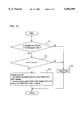
- FIG. 7 is a flow chart showing the procedure for judging the arrival of a first transitional mode, and controlling the reduction of a fuel pressure in the high-pressure accumulator in the first transitional mode;
- FIG. 8 is a timing chart showing a fuel injection waveform in the first transitional mode, and the driving of the injector and change-over valve;
- FIG. 9 is a diagram showing increasing variation of an indicated value, which relates to a low-pressure fuel in a low-pressure accumulator, in accordance with that of engine load and speed;
- FIG. 10 is a diagram showing variation of the indicated value in accordance with that of an engine load, and a response delay of an actual pressure with respect to the indicated value;
- FIG. 11 is a flow chart showing the judgement of a second transitional mode, and the procedure for carrying; out a control operation in the second transitional mode;
- FIG. 12 is a diagram showing variations with the lapse of time of an injector driving signal, a change-over valve driving signal, a fuel pressure at an inlet of the injector and a fuel pressure in the low-pressure accumulator during a fuel injection control operation in the second transitional mode.
- FIG. 1 is a schematic construction diagram of an accumulator type fuel injection control apparatus as an embodiment of the present invention
- FIG. 2 a schematic diagram showing the connection of primary elements of the fuel injection control apparatus shown in FIG. 1 with an injector for each cylinder of an engine.
- the accumulator type fuel injection control apparatus is mounted on, for example, a 6-series-cylinder diesel engine (not shown), and a high-pressure pump 1 is provided with, for example, two plunger pumps 20 shown in FIG. 3, which correspond to three front cylinder, and three rear cylinders respectively of the 6-series-cylinder diesel engine, cams 22 for driving a plunger 21 for the three front cylinders and a plunger 21 for driving the three rear cylinders being provided with three bulging portions, three force feed strokes being made while the shaft of the high-pressure pump 1 makes one full turn to force feed a fuel.
- a 6-series-cylinder diesel engine not shown
- a high-pressure pump 1 is provided with, for example, two plunger pumps 20 shown in FIG. 3, which correspond to three front cylinder, and three rear cylinders respectively of the 6-series-cylinder diesel engine, cams 22 for driving a plunger 21 for the three front cylinders and a plunger 21 for driving the three rear cylinders being provided with three bulging portions, three force feed strokes
- the regulation of the force feed stroke is made by regulating the closing time of an electromagnetic valve 23 provided on the discharge side of the plunger pumps 20, and, while this electromagnetic valve 23 is opened, the force feed operations of the plunger pumps 20 are ineffective.
- the electromagnetic valve 23 is controlled by an electronic control unit 8 which will be described later.
- the electronic control unit (ECU) 8 as a fuel control means for the accumulator type fuel injection control apparatus controls the electromagnetic valve 23 in the high-pressure fuel pump 1 in accordance with an engine speed Ne detected by an engine speed sensor 8a and an accelerator pedal stepping amount (degree of opening of the accelerator) Acc detected by a degree of opening of accelerator sensor (not shown) to variably regulate the force feed stroke, and feedback controls the force feed stroke (discharge pressure) in accordance with a fuel pressure P HP detected by a pressure sensor 3a provided on a high-pressure accumulator 3, whereby a high-pressure fuel suiting the operating condition of the engine is obtained.
- the fuel pressurized by the high-pressure pump 1 is stored in the high-pressure accumulator 3.
- This high-pressure accumulator 3 is common to all cylinders, and communicates with a fuel passage 10a.
- a fuel injection rate switching change-over valve (first control valve) 5 comprising, for example, a two-way electromagnetic valve is provided (FIG. 2) correspondingly to each cylinder with a check valve 32 which permits a fuel to flow only from the upstream side to the downstream side provided on the immediate downstream side of the change-over valve 5.
- a low-pressure accumulator (second accumulator) 4 common to all cylinders is connected via a fuel passage 10b, which branches from the fuel passage 10a, to the portion of the fuel passage 10a which is on the downstream side of the check valve 32.
- a check valve 6 and a bypass passage shunting the check valve 6 are provided, an orifice 6a being provided in this bypass passage.
- the check valve 6 is adapted to allow a fuel to flow only from the low-pressure accumulator 4 toward the fuel passage 10a. When the fuel pressure in the fuel passage 10a is higher than that in the fuel passage 10b, the fuel in the fuel passage 10a flows into the fuel passage 10b through the orifice 6a, and then into the low-pressure accumulator 4.
- a pressure control valve (second control valve) 34 operated under the control of the electronic control unit 8 and adapted to control the fuel pressure in the low-pressure accumulator 4 is provided.
- the low-pressure accumulator 4 is provided with a pressure sensor 4a for detecting a fuel pressure P LP therein.
- the electronic control unit 8 is adapted to control the pressure control valve 34 on the basis of an actual pressure P LP detected by the pressure sensor 4a, in such manner that the fuel pressure in the low-pressure accumulator 4 attains a level which suits the operating condition of the engine represented by the engine speed Ne and accelerator pedal stepping amount Acc.
- An injector 9 as a fuel injection nozzle provided in each cylinder of the engine has a pressure control chamber 11 connected to the fuel passage 10a via an orifice 15, and a fuel chamber (fuel reservoir) 12, the pressure control chamber 11 being connected to the fuel tank 17 via an orifice 16 and a fuel return passage 10c.
- a fuel injection time control switch valve 7 comprising, for example, a two-way electronic valve is connected to an intermediate portion of the fuel return passage 10c. The switch valve 7 may be provided in the injector.
- the injector 9 has a needle valve 13 adapted to open and close a nozzle (injection port) 9a, and a hydraulic piston 14 housed slidably in the pressure control chamber 11, and the needle valve 13 is urged to the side of the nozzle 9a by a spring (not shown) and closed.
- a resultant force of the resilient force of the spring and the fuel pressure is imparted to the needle valve 13, so that the needle valve 13 closes the nozzle 9a against the fuel pressure in the fuel chamber 12.
- the needle valve 13 is moved toward the hydraulic piston 14 against the resilient force of the spring due to the fuel pressure in the fuel chamber 12 to open the nozzle 9a, so that the fuel in the fuel chamber 12 is injected from the nozzle 9a into a combustion chamber of the engine.
- the fuel pressure in the high-pressure accumulator 3 and that in the low-pressure accumulator 4 are controlled under the control of the electronic control unit 8 so that these fuel pressures suit the operating condition of the engine, and a fuel injection period (fuel injection starting and finishing time) and low-pressure injection period are set in accordance with the operating condition (engine speed and accelerator pedal stepping amount) of the engine.
- the change-over valve 5 and switch valve 7 are all closed until the fuel injection starting time comes, and a low-pressure fuel is supplied from the low-pressure accumulator 4 to the portion of the fuel passage 10a which is on the downstream side of the change-over valve 5, and further to the pressure control chamber 11 and fuel chamber 12 of the injector 9. Since the switch valve 7 is closed, the fuel supplied to the interior of the pressure control chamber 11 is applied to the needle valve 13 via the hydraulic piston 14 to close the nozzle 9a with the needle valve 13, whereby the injector is closed.
- the injection rate switching change-over valve 5 is opened with the injection time control switch valve 7 left open, and a high-pressure fuel is supplied to the fuel chamber 12, the high-pressure fuel being injected from the injector 9. Namely, high-pressure injection of an injection rate higher than that of the low-pressure injection is executed.
- the injection time control switch valve 7 When the fuel injection finishing time comes, the injection time control switch valve 7 is closed, and the high-pressure fuel supplied from the fuel passage 10a to the pressure control chamber 11 through the orifice 15 works on the needle valve 13 via the hydraulic piston 14 to cause the needle valve 13 to close the nozzle 9a, so that the fuel injection from the nozzle 9a finishes.
- the fuel injection rate suddenly falls, and rates of discharge of black smoke and particulates (granular substances PM) from the engine is reduced.
- the injection rate switching change-over valve 5 is closed simultaneously with the closure of the switch valve 7 at the fuel injection finishing time, or at a point in time at which a predetermined period of time has elapsed after the fuel injection time was terminated.
- FIG. 6 shows an example of a pressure map of the high-pressure accumulator 3, in which the pressure (fuel pressure) in the high-pressure accumulator 3 increases in accordance with an increase in a load (degree of opening of the accelerator) as shown by an arrow.
- FIG. 7 is a flow chart showing procedures for judging the arrival of a first transitional mode and carrying out a pressure reduction control operation for the high-pressure accumulator in the first transitional mode
- FIG. 8 a timing chart showing a fuel injection waveform in the first transitional mode and the driving of the injector and change-over valve.
- the electronic control unit 8 judges that a transitional time has come, sets an indicated pressure of the high-pressure accumulator 3 in accordance with the operating condition of the engine, judges (Step S1) on the basis of a signal from the pressure sensor 3a provided on the high-pressure accumulator 3 whether a rate of decrease in the indicated pressure of the high-pressure accumulator is not lower than a predetermined level, i.e.
- Step S2 the operation mode to the transitional mode when the result of the judgement is affirmative (Yes).
- the judgement of the arrival of the first transitional mode may be made on the basis of the degree of opening of the accelerator.
- Step S2 the electronic control unit 8 executes a pressure reduction control operation for the high-pressure accumulator 3 in the transitional time.
- the force feed operation of the high-pressure pump 1 is temporarily stopped, i.e., put in a non-force-feed-conducting state, the opening time of the change-over valve 5 (FIG. 1) being extended to increase the discharge rate of the fuel from the high-pressure accumulator 3 to the low-pressure accumulator 4 and thereby promote the reduction of the fuel pressure.
- a driving signal for the change-over valve 5 in a regular mode is turned off as shown by a broken line after the differential time Te has elapsed after the driving signal was turned off.
- the pressure control valve 34 is adapted to discharge the fuel which has flowed into the low-pressure accumulator 4 to the fuel tank 17, whereby the pressure in the low-pressure accumulator 4 is controlled to a predetermined level. Consequently, the pressure (pressure in the fuel passage 10a) at the inlet of the injector 9 and that in the high-pressure accumulator 3 decreases.
- the high-pressure pump 1 is put in a force feed stopping condition in the transitional time, and the opening time of the change-over valve 5 is extended (first embodiment).
- the stopping of a force feed operation of the high-pressure fuel pump 1 is done by opening the electromagnetic valve 23 shown in FIG. 3.
- the extension of the opening time of the change-over valve 5 is carried out by computing maximum extension time ⁇ Te of the change-over valve 5 within the time T which is between the time of current injection finishing time of the injector 9 and the subsequent injection starting time as shown in FIG. 8.
- effective extension time corresponding to the operating condition (each load) of the engine can be determined.
- the electronic control unit 8 opens the electromagnetic valve 23 of the fuel pump 1 to temporarily stop (the force feeding of the fuel is not carried out) the fuel supply to the high-pressure accumulator 3 and open the change-over valve 5 during the maximum extension time ⁇ Te which is after the closure of the injector 9. Consequently, the flow rate of the high-pressure fuel supplied from the, high-pressure accumulator 3 to the low-pressure accumulator 4 increases.
- the pressure control valve 34 discharges the high-pressure fuel which has flowed into the low-pressure accumulator 4 into the fuel tank 17 to control the pressure in the low-pressure accumulator 4 to a predetermined level.
- the flow rate of the fuel from the high-pressure accumulator 3 to the low-pressure accumulator 4 is increased to positively carry out the reduction of the fuel pressure in the high-pressure accumulator 3, whereby the heightening of the rate of pressure decrease (rate of pressure drop) ⁇ Pb in the high-pressure accumulator 3 is promoted to have the same fuel pressure reach the indicated level early.
- This enables a response delay of an actual pressure with respect to the indicated pressure of the high-pressure accumulator 3 to be minimized, and the exhaust gas and fuel performance to be improved.
- the reducing of the pressure in the high-pressure accumulator 3 is done until the pressure in the low-pressure accumulator 4 has attained a predetermined level, and the time during which the change-over valve 5 is opened is up to a point in time which is a predetermined period of time ( ⁇ Taf+ ⁇ Tred) before the subsequent opening time of the injector 9.
- ⁇ Taf+ ⁇ Tred a predetermined period of time before the subsequent opening time of the injector 9.
- Step S1 when the result of judgement in Step S1 is negative (No), i.e., when a judgement that the rate of decrease in the indicated pressure in the high-pressure accumulator 3 is lower than a predetermined level is given, the electronic control unit 8 finishes the first transitional mode, and transfers (Step S3) the mode to a regular mode.
- a change-over valve opening and closing control operation in a second transitional mode which is different from the above-mentioned regular mode is carried out during an accelerating operation of the engine to promote the formation of fuel pressure in the low-pressure accumulator, and enable proper low-pressure injection to be executed early (second embodiment).
- an electronic control unit 8 executes a control mode judgement routine shown in FIG. 11 in a predetermined cycle.
- a target value (indicated value) P LPTAR of a low-pressure fuel suiting the operating condition of the engine is selected from, for example, an engine operating condition and indicated pressure map (not shown) on the basis of, for example, an engine speed Ne and an accelerator pedal stepping amount Acc.
- the variation amount of the indicated pressure from the preceding cycle to the current cycle is determined on the basis of an indicated pressure P LPTAR (n) of the low-pressure fuel calculated in the current cycle of the above-mentioned calculation routine and a calculated value P LPTAR (n-1) in the preceding cycle thereof.
- a variation rate dP LPTAR of the indicated pressure is further determined by dividing this variation amount of the indicated pressure by a calculation routine execution cycle. This variation rate dP LPTAR is then judged as to whether it exceeds a set level or not (Step S11).
- the set value regarding the variation rate of the indicated pressure is a variation rate of an upper permissible limit which does not cause a non-acceptable delay to occur in a response of the actual pressure with respect to the low-pressure fuel even when a change-over valve opening and closing control operation in a regular mode is executed, and this variation rate is determined in advance, for example, by conducting experiments. Therefore, when a change-over valve opening and closing control operation is carried out in a case where the variation rate of the indicated pressure exceeds the set level, a non-acceptable delay occurs in a response of the actual pressure with respect to the indicated pressure, and low-pressure injection suiting the operating condition of the engine cannot be carried out in some cases.
- Step S11 When the variation rate of the indicated pressure is not higher than the set level, a non-acceptable response delay does not occur even when a change-over valve opening and closing control operation is carried out in a regular mode, and low-pressure injection suiting the operating condition of the engine can be carried out.
- Step S11 When the result of judgement in Step S11 is negative (No), i.e., when the variation rate of the indicated pressure does not exceed the set level, a judgement that a response delay obstructing proper low-pressure injection does not occur even when the change-over valve opening and closing control operation is carried out in a regular mode is carried out is given, and the already-described change-over valve opening and closing control operation in a regular mode and fuel injection control operation are carried out (Step S12).
- Step S11 When a judgement that the variation rate of the indicated pressure exceeds the set level is given in Step S11, an output P LP from a pressure sensor 4a which represents the actual fuel pressure in the low-pressure accumulator 4 is read, and the actual pressure P LP is judged (Step S13) as to whether it is lower than the indicated pressure P LPTAR or not.
- Step 13 When a judgement that the actual pressure P LP is not lower than the indicated pressure P LPTAR is given in Step 13, it is construed as a judgement that low-pressure injection can be carried out properly even when the change-over valve opening and closing control operation is carried out in a regular mode, so that the change-over valve opening and closing control operation in a regular mode and the fuel injection control operation are carried out (Step S12).
- Step S13 When the result of judgement in Step S13 is affirmative (Yes), i.e., when a judgement that the actual pressure PLP is lower than the indicated pressure PLPTAR is given in Step S13 following the judgement that the variation rate of the indicated pressure exceeds the set level given in Step S11, it is construed as a judgement that, when the change-over valve opening and closing control operation in a regular mode keeps being carried out, a non-acceptable delay occurs in a response of the actual pressure with respect to the indicated pressure to render it unable to carry out a proper low-pressure injection operation, so that the operation mode is transferred to a second transitional mode (Step S14).
- an injection time control switch valve 7 is driven at such time that permits obtaining a fuel injection period suiting the operating condition of the engine, and the pressurized fuel in a fuel chamber 12 is injected from a nozzle port of an injector 9 while the switch valve 7 is opened.
- the opening of an injection rate switching change-over valve 5 is timed in the same manner as in a regular mode, and the low-pressure injection is switched at this time to high-pressure injection.
- the time at which the change-over valve 5 is closed is set to the time later than that in a regular mode.
- a predetermined period of time ⁇ Te between the fuel injection finishing time (point in time at which an injector driving signal falls) and the change-over valve closing time (point in time at which a change-over valve driving signal falls) is extended by extension time ⁇ Tesad.
- the time for supplying a pressurized fuel from the high-pressure accumulator 3 to the low-pressure accumulator 4 via a fuel passage 10a and an orifice 6a becomes longer than flat in a regular mode, and the supplying of the pressurized fuel to the low-pressure accumulator 4 is carried out positively while the change-over valve 5 is opened even after the injector 9 is closed. Consequently, an increased portion of the fuel pressure in the low-pressure accumulator 4 in the second transitional mode becomes large as shown by a solid line in FIG. 12 as compared with that (broken line) in a case where the change-over valve opening period is not extended.
- the formation of fuel pressure in the low-pressure accumulator 4 is promoted, and the fuel pressure in the second accumulator reaches in a short period of time the indicated level corresponding to the operating condition of the engine in a transitional operation.
- FIG. 12 shows for the convenience of illustration a case where the pressure of the low-pressure fuel reaches an indicated level owing to the extending of the change-over valve opening period in only a fuel injection cycle which follows immediately after the execution of transfer of the operation mode to the second transitional mode.
- the change-over valve opening period may be extended in a plurality of fuel injection cycles in some cases after the execution of transfer of the operation mode to the second transitional mode.
- the closing time of the change-over valve 5 is set to the time earlier than a subsequent opening of the injector 9 by a period of time equal to the sum of a predetermined period Tdra and a marginal period ⁇ Tdra.
- the predetermined period Tdra corresponds to the time required by the fuel pressure in the fuel passage 10a, i.e. the fuel pressure in the combustion chamber (inlet of the injector) of the injector to decrease after the closure of the change-over valve 5 to a level at which low-pressure injection is executed.
- This predetermined period Tdra can be determined, for example, by conducting experiments.
- the change-over valve 5 When the change-over valve 5 is thus closed at the time earlier than subsequent fuel injection starting time by at least the predetermined period Tdra, the fuel pressure at the inlet of the injector can be set stably to a level substantially equal to that of the low-pressure injection pressure. As a result, low-pressure injection in each fuel injection cycle is carried out properly, and the fuel consumption and exhaust gas characteristics are improved.
- Step S13 of the judgement routine of FIG. 11 When a judgement that the actual pressure P LP in the low-pressure accumulator 4 exceeds the indicated pressure P LPTAR is given in Step S13 of the judgement routine of FIG. 11, it is construed as a judgement that the formation of a fuel pressure in the low-pressure accumulator 4 is completed, and the operation mode is transferred to a regular mode.
- the present invention is not limited to the above-described embodiments, and can be modified variously.
- the variation rate of the indicated pressure is determined directly on the basis of the amounts of variation of the current and preceding indicated pressures P LPTAR , and a judgement that "request for accelerated operation is made" is given when the variation rate of the indicated pressure has exceeded a set level, the operation mode being transferred a transitional mode when the actual pressure P LP is lower than the indicated level, to extend the opening time of the change-over valve.
- a judgement that "request for accelerated operation is made” may be given when something, instead of the above-mentioned variation rate, representative of a degree of variation of the operating condition of an engine, for example, a variation rate of the accelerator pedal stepping amount has exceeded a set level.
- the variation rate of the indicated pressure may be determined indirectly on the basis of that of the accelerator pedal stepping amount.
- first and second embodiments may be provided independently, or the constitution of both thereof at once.
Landscapes
- Engineering & Computer Science (AREA)
- Chemical & Material Sciences (AREA)
- Combustion & Propulsion (AREA)
- Mechanical Engineering (AREA)
- General Engineering & Computer Science (AREA)
- Oil, Petroleum & Natural Gas (AREA)
- Physics & Mathematics (AREA)
- Fluid Mechanics (AREA)
- Fuel-Injection Apparatus (AREA)
- Electrical Control Of Air Or Fuel Supplied To Internal-Combustion Engine (AREA)
Abstract
Description
Claims (12)
Applications Claiming Priority (4)
| Application Number | Priority Date | Filing Date | Title |
|---|---|---|---|
| JP10-329240 | 1998-11-19 | ||
| JP32924098A JP3377033B2 (en) | 1998-11-19 | 1998-11-19 | Accumulator type fuel injection device |
| JP11-040479 | 1999-02-18 | ||
| JP04047999A JP3729239B2 (en) | 1999-02-18 | 1999-02-18 | Accumulated fuel injection control device |
Publications (1)
| Publication Number | Publication Date |
|---|---|
| US6092509A true US6092509A (en) | 2000-07-25 |
Family
ID=26379938
Family Applications (1)
| Application Number | Title | Priority Date | Filing Date |
|---|---|---|---|
| US09/443,009 Expired - Fee Related US6092509A (en) | 1998-11-19 | 1999-11-18 | Accumulator type fuel injection system |
Country Status (3)
| Country | Link |
|---|---|
| US (1) | US6092509A (en) |
| EP (1) | EP1002948B1 (en) |
| DE (1) | DE69905685T2 (en) |
Cited By (24)
| Publication number | Priority date | Publication date | Assignee | Title |
|---|---|---|---|---|
| US6192862B1 (en) * | 1998-11-19 | 2001-02-27 | Mitsubishi Jidosha Kogyo Kabushiki Kaisha | Accumulator type fuel injection system |
| US6363914B1 (en) * | 1999-09-22 | 2002-04-02 | Mitsubishi Jidosha Kogyo Kabushiki Kaisha | Accumulator fuel injection system |
| US6439202B1 (en) * | 2001-11-08 | 2002-08-27 | Cummins Inc. | Hybrid electronically controlled unit injector fuel system |
| US6457453B1 (en) * | 2000-03-31 | 2002-10-01 | Mitsubishi Jidosha Kogyo Kabushiki Kaisha | Accumulator fuel-injection apparatus |
| US6644278B2 (en) * | 2000-11-29 | 2003-11-11 | Robert Bosch Gmbh | Pressure controlled injector for injection systems with high pressure collecting area |
| US6651626B2 (en) * | 2001-03-15 | 2003-11-25 | Robert Bosch Gmbh | Fuel injection apparatus for internal combustion engines |
| US20040016421A1 (en) * | 2002-04-23 | 2004-01-29 | Robert Bosch Gmbh | Fuel injection device for an internal combustion engine |
| US6684856B2 (en) * | 2001-11-16 | 2004-02-03 | Mitsubishi Fuso Truck And Bus Corporation | Fuel injection apparatus of engine |
| US6684855B2 (en) * | 2001-03-23 | 2004-02-03 | Toyota Jidosha Kabushiki Kaisha | Common rail fuel injection apparatus and control method thereof |
| US6718947B1 (en) * | 1999-08-20 | 2004-04-13 | Robert Bosch Gmbh | Fuel injection method and systems for an internal combustion engine |
| US6725840B1 (en) * | 1999-08-20 | 2004-04-27 | Robert Bosch Gmbh | Fuel injection device |
| US6755181B2 (en) | 2000-09-04 | 2004-06-29 | Siemens Vdo Automotive | Method for controlling the amount of fuel injected in a direct injection internal combustion engine |
| US20040163626A1 (en) * | 2003-02-20 | 2004-08-26 | Stockner Alan R. | End of injection rate shaping |
| US20040237937A1 (en) * | 2001-09-12 | 2004-12-02 | Klaus Joos | Method, computer programme, control and/or regulation device for operation of an internal combustion engine and fuel system for an internal combustion engine |
| US20060144366A1 (en) * | 2002-08-24 | 2006-07-06 | Hans-Christoph Magel | Fuel injection device |
| US20070079807A1 (en) * | 2005-10-12 | 2007-04-12 | Denso Corporation | Fuel injection apparatus having fuel supplier for displacement amplifying chamber |
| US20070272204A1 (en) * | 2006-05-24 | 2007-11-29 | Gibson Dennis H | Multi-source fuel system having grouped injector pressure control |
| US20070272213A1 (en) * | 2006-05-24 | 2007-11-29 | Gibson Dennis H | Multi-source fuel system having closed loop pressure control |
| US20070277783A1 (en) * | 2006-05-31 | 2007-12-06 | Gibson Dennis H | Multi-source fuel system for variable pressure injection |
| US7398763B2 (en) | 2005-11-09 | 2008-07-15 | Caterpillar Inc. | Multi-source fuel system for variable pressure injection |
| US20080296413A1 (en) * | 2005-07-18 | 2008-12-04 | Marco Ganser | Accumulator Injection System for an Internal Combustion Engine |
| US20100132669A1 (en) * | 2008-12-03 | 2010-06-03 | Hyundai Motor Company | Fuel supply apparatus for engine and injector for the same |
| US20130032126A1 (en) * | 2011-08-01 | 2013-02-07 | Toyota Jidosha Kabushiki Kaisha | Fuel supply apparatus |
| US20140095051A1 (en) * | 2012-09-28 | 2014-04-03 | Pratt & Whitney Canada Corp. | Adaptive fuel manifold filling function for improved engine start |
Families Citing this family (3)
| Publication number | Priority date | Publication date | Assignee | Title |
|---|---|---|---|---|
| DE10112154A1 (en) * | 2001-03-14 | 2002-09-26 | Bosch Gmbh Robert | Fuel injection system |
| DE10123995A1 (en) * | 2001-05-17 | 2002-11-21 | Bosch Gmbh Robert | Fuel injection device has third electrically operated control valve to control second connection between pump working cavity and relief cavity |
| DE10131783B4 (en) * | 2001-07-03 | 2006-03-16 | Robert Bosch Gmbh | Method for operating an internal combustion engine |
Citations (7)
| Publication number | Priority date | Publication date | Assignee | Title |
|---|---|---|---|---|
| US5146894A (en) * | 1989-03-10 | 1992-09-15 | Robert Bosch Gmbh | Reservoir-type fuel injection system |
| US5619970A (en) * | 1995-05-13 | 1997-04-15 | Lucas Industries, Public. Limited Company | Fuel pumping apparatus |
| US5619969A (en) * | 1995-06-12 | 1997-04-15 | Cummins Engine Company, Inc. | Fuel injection rate shaping control system |
| US5622152A (en) * | 1994-07-08 | 1997-04-22 | Mitsubishi Jidosha Kogyo Kabushiki Kaisha | Pressure storage fuel injection system |
| US5642714A (en) * | 1994-11-12 | 1997-07-01 | Lucas Industries | Fuel system |
| US5732679A (en) * | 1995-04-27 | 1998-03-31 | Isuzu Motors Limited | Accumulator-type fuel injection system |
| US5839413A (en) * | 1997-04-28 | 1998-11-24 | The Rexroth Corporation | Quick start HEUI system |
Family Cites Families (4)
| Publication number | Priority date | Publication date | Assignee | Title |
|---|---|---|---|---|
| DE4313852B4 (en) * | 1993-04-28 | 2004-11-25 | Robert Bosch Gmbh | Fuel injection device for internal combustion engines |
| DE4445586A1 (en) * | 1994-12-20 | 1996-06-27 | Bosch Gmbh Robert | Method for reducing fuel pressure in a fuel injector |
| DE19640826B4 (en) * | 1995-10-03 | 2004-11-25 | Nippon Soken, Inc., Nishio | Storage fuel injection device and pressure control device therefor |
| KR100354216B1 (en) * | 1996-08-29 | 2003-02-20 | 미쯔비시 지도샤 고교 가부시끼가이샤 | Fuel Injection Apparatus |
-
1999
- 1999-11-18 DE DE69905685T patent/DE69905685T2/en not_active Expired - Lifetime
- 1999-11-18 US US09/443,009 patent/US6092509A/en not_active Expired - Fee Related
- 1999-11-18 EP EP99122946A patent/EP1002948B1/en not_active Expired - Lifetime
Patent Citations (7)
| Publication number | Priority date | Publication date | Assignee | Title |
|---|---|---|---|---|
| US5146894A (en) * | 1989-03-10 | 1992-09-15 | Robert Bosch Gmbh | Reservoir-type fuel injection system |
| US5622152A (en) * | 1994-07-08 | 1997-04-22 | Mitsubishi Jidosha Kogyo Kabushiki Kaisha | Pressure storage fuel injection system |
| US5642714A (en) * | 1994-11-12 | 1997-07-01 | Lucas Industries | Fuel system |
| US5732679A (en) * | 1995-04-27 | 1998-03-31 | Isuzu Motors Limited | Accumulator-type fuel injection system |
| US5619970A (en) * | 1995-05-13 | 1997-04-15 | Lucas Industries, Public. Limited Company | Fuel pumping apparatus |
| US5619969A (en) * | 1995-06-12 | 1997-04-15 | Cummins Engine Company, Inc. | Fuel injection rate shaping control system |
| US5839413A (en) * | 1997-04-28 | 1998-11-24 | The Rexroth Corporation | Quick start HEUI system |
Cited By (37)
| Publication number | Priority date | Publication date | Assignee | Title |
|---|---|---|---|---|
| US6192862B1 (en) * | 1998-11-19 | 2001-02-27 | Mitsubishi Jidosha Kogyo Kabushiki Kaisha | Accumulator type fuel injection system |
| US6718947B1 (en) * | 1999-08-20 | 2004-04-13 | Robert Bosch Gmbh | Fuel injection method and systems for an internal combustion engine |
| US6725840B1 (en) * | 1999-08-20 | 2004-04-27 | Robert Bosch Gmbh | Fuel injection device |
| US6363914B1 (en) * | 1999-09-22 | 2002-04-02 | Mitsubishi Jidosha Kogyo Kabushiki Kaisha | Accumulator fuel injection system |
| US6457453B1 (en) * | 2000-03-31 | 2002-10-01 | Mitsubishi Jidosha Kogyo Kabushiki Kaisha | Accumulator fuel-injection apparatus |
| US6755181B2 (en) | 2000-09-04 | 2004-06-29 | Siemens Vdo Automotive | Method for controlling the amount of fuel injected in a direct injection internal combustion engine |
| US6644278B2 (en) * | 2000-11-29 | 2003-11-11 | Robert Bosch Gmbh | Pressure controlled injector for injection systems with high pressure collecting area |
| US6651626B2 (en) * | 2001-03-15 | 2003-11-25 | Robert Bosch Gmbh | Fuel injection apparatus for internal combustion engines |
| US6684855B2 (en) * | 2001-03-23 | 2004-02-03 | Toyota Jidosha Kabushiki Kaisha | Common rail fuel injection apparatus and control method thereof |
| US20040237937A1 (en) * | 2001-09-12 | 2004-12-02 | Klaus Joos | Method, computer programme, control and/or regulation device for operation of an internal combustion engine and fuel system for an internal combustion engine |
| US7171952B2 (en) * | 2001-09-12 | 2007-02-06 | Robert Bosch Gmbh | Method, computer program, control and/or regulation device for operation of an internal combustion engine and fuel system for an internal combustion engine |
| US6439202B1 (en) * | 2001-11-08 | 2002-08-27 | Cummins Inc. | Hybrid electronically controlled unit injector fuel system |
| US6684856B2 (en) * | 2001-11-16 | 2004-02-03 | Mitsubishi Fuso Truck And Bus Corporation | Fuel injection apparatus of engine |
| US20040016421A1 (en) * | 2002-04-23 | 2004-01-29 | Robert Bosch Gmbh | Fuel injection device for an internal combustion engine |
| US6823846B2 (en) * | 2002-04-23 | 2004-11-30 | Robert Bosch Gmbh | Fuel injection device for an internal combustion engine |
| US7267107B2 (en) * | 2002-08-24 | 2007-09-11 | Robert Bosch Gmbh | Fuel injection device |
| US20060144366A1 (en) * | 2002-08-24 | 2006-07-06 | Hans-Christoph Magel | Fuel injection device |
| US20040163626A1 (en) * | 2003-02-20 | 2004-08-26 | Stockner Alan R. | End of injection rate shaping |
| US7059301B2 (en) * | 2003-02-20 | 2006-06-13 | Caterpillar Inc. | End of injection rate shaping |
| US20080296413A1 (en) * | 2005-07-18 | 2008-12-04 | Marco Ganser | Accumulator Injection System for an Internal Combustion Engine |
| US7603984B2 (en) | 2005-07-18 | 2009-10-20 | Ganser-Hydromag Ag | Accumulator injection system for an internal combustion engine |
| CN101223352B (en) * | 2005-07-18 | 2010-12-08 | 甘瑟-许德罗玛格股份公司 | Accumulator injection systems for internal combustion engines |
| US20070079807A1 (en) * | 2005-10-12 | 2007-04-12 | Denso Corporation | Fuel injection apparatus having fuel supplier for displacement amplifying chamber |
| US7520267B2 (en) * | 2005-10-12 | 2009-04-21 | Denso Corporation | Fuel injection apparatus having fuel supplier for displacement amplifying chamber |
| US7398763B2 (en) | 2005-11-09 | 2008-07-15 | Caterpillar Inc. | Multi-source fuel system for variable pressure injection |
| US20070272213A1 (en) * | 2006-05-24 | 2007-11-29 | Gibson Dennis H | Multi-source fuel system having closed loop pressure control |
| US7353800B2 (en) | 2006-05-24 | 2008-04-08 | Caterpillar Inc. | Multi-source fuel system having grouped injector pressure control |
| US20070272204A1 (en) * | 2006-05-24 | 2007-11-29 | Gibson Dennis H | Multi-source fuel system having grouped injector pressure control |
| US7431017B2 (en) * | 2006-05-24 | 2008-10-07 | Caterpillar Inc. | Multi-source fuel system having closed loop pressure control |
| US7392791B2 (en) * | 2006-05-31 | 2008-07-01 | Caterpillar Inc. | Multi-source fuel system for variable pressure injection |
| US20070277783A1 (en) * | 2006-05-31 | 2007-12-06 | Gibson Dennis H | Multi-source fuel system for variable pressure injection |
| US20100132669A1 (en) * | 2008-12-03 | 2010-06-03 | Hyundai Motor Company | Fuel supply apparatus for engine and injector for the same |
| US8215287B2 (en) * | 2008-12-03 | 2012-07-10 | Hyundai Motor Company | Fuel supply apparatus for engine and injector for the same |
| US20130032126A1 (en) * | 2011-08-01 | 2013-02-07 | Toyota Jidosha Kabushiki Kaisha | Fuel supply apparatus |
| US8944030B2 (en) * | 2011-08-01 | 2015-02-03 | Toyota Jidosha Kabushiki Kaisha | Fuel supply apparatus |
| US20140095051A1 (en) * | 2012-09-28 | 2014-04-03 | Pratt & Whitney Canada Corp. | Adaptive fuel manifold filling function for improved engine start |
| US9541005B2 (en) * | 2012-09-28 | 2017-01-10 | Pratt & Whitney Canada Corp. | Adaptive fuel manifold filling function for improved engine start |
Also Published As
| Publication number | Publication date |
|---|---|
| DE69905685D1 (en) | 2003-04-10 |
| DE69905685T2 (en) | 2003-10-02 |
| EP1002948A2 (en) | 2000-05-24 |
| EP1002948B1 (en) | 2003-03-05 |
| EP1002948A3 (en) | 2001-08-08 |
Similar Documents
| Publication | Publication Date | Title |
|---|---|---|
| US6092509A (en) | Accumulator type fuel injection system | |
| US6792919B2 (en) | Accumulator type fuel injection system | |
| US7328687B2 (en) | Fuel supply apparatus for internal combustion engine | |
| US5622152A (en) | Pressure storage fuel injection system | |
| EP1087130B1 (en) | Accumulator fuel injection system | |
| US6457453B1 (en) | Accumulator fuel-injection apparatus | |
| US7007671B2 (en) | Fuel injection system | |
| US20030051709A1 (en) | Method and system for controlling fuel injection | |
| US6192862B1 (en) | Accumulator type fuel injection system | |
| US5906188A (en) | Accumulator type fuel injection control system and the method thereof | |
| US7107966B2 (en) | Fuel injection system | |
| JP2636394B2 (en) | Fuel injection device | |
| US7225794B2 (en) | Common rail fuel injection system | |
| JP3729239B2 (en) | Accumulated fuel injection control device | |
| JP3377033B2 (en) | Accumulator type fuel injection device | |
| JP4135254B2 (en) | Fuel injection device for internal combustion engine | |
| JP3377032B2 (en) | Accumulator type fuel injection device | |
| US20100313854A1 (en) | Fuel injection control device of internal combustion engine | |
| JP3356087B2 (en) | Accumulator type fuel injection device | |
| JP3812620B2 (en) | Accumulated fuel injection system | |
| JP3952111B2 (en) | Accumulated fuel injection system | |
| JP2000161169A (en) | Accumulator type fuel injection device | |
| JP2000154750A (en) | Accumulator type fuel injection device | |
| KR20040045632A (en) | an apparatus and the method for fuel injection pressure controling of common rail in diesel engine |
Legal Events
| Date | Code | Title | Description |
|---|---|---|---|
| AS | Assignment |
Owner name: MITSUBISHI JIDOSHA KOGYO KABUSHIKI KAISHA, JAPAN Free format text: ASSIGNMENT OF ASSIGNORS INTEREST;ASSIGNORS:TANABE, KEIKI;KOHKETSU, SUSUMU;REEL/FRAME:010516/0438 Effective date: 19991220 |
|
| FEPP | Fee payment procedure |
Free format text: PAYOR NUMBER ASSIGNED (ORIGINAL EVENT CODE: ASPN); ENTITY STATUS OF PATENT OWNER: LARGE ENTITY |
|
| AS | Assignment |
Owner name: MITSUBISHI FUSO TRUCK AND BUS CORPORATION, JAPAN Free format text: ASSIGNMENT OF ASSIGNORS INTEREST;ASSIGNOR:MITSUBISHI JIDOSHA KOGYO KABUSHIKI KAISHA;REEL/FRAME:014402/0954 Effective date: 20030106 |
|
| FPAY | Fee payment |
Year of fee payment: 4 |
|
| AS | Assignment |
Owner name: MITSUBISHI FUSO TRUCK AND BUS CORPORATION, JAPAN Free format text: CHANGE OF ADDRESS;ASSIGNOR:MITSUBISHI FUSO TRUCK AND BUS CORPORATION;REEL/FRAME:014822/0559 Effective date: 20030501 |
|
| FPAY | Fee payment |
Year of fee payment: 8 |
|
| REMI | Maintenance fee reminder mailed | ||
| LAPS | Lapse for failure to pay maintenance fees | ||
| STCH | Information on status: patent discontinuation |
Free format text: PATENT EXPIRED DUE TO NONPAYMENT OF MAINTENANCE FEES UNDER 37 CFR 1.362 |
|
| FP | Lapsed due to failure to pay maintenance fee |
Effective date: 20120725 |