US6089316A - Wire-wrapped well screen - Google Patents
Wire-wrapped well screen Download PDFInfo
- Publication number
- US6089316A US6089316A US09/123,197 US12319798A US6089316A US 6089316 A US6089316 A US 6089316A US 12319798 A US12319798 A US 12319798A US 6089316 A US6089316 A US 6089316A
- Authority
- US
- United States
- Prior art keywords
- spacer
- cylinder
- recited
- spacers
- wire
- Prior art date
- Legal status (The legal status is an assumption and is not a legal conclusion. Google has not performed a legal analysis and makes no representation as to the accuracy of the status listed.)
- Expired - Lifetime
Links
- 125000006850 spacer group Chemical group 0.000 claims abstract description 135
- 239000012530 fluid Substances 0.000 claims abstract description 35
- 230000001154 acute effect Effects 0.000 claims description 14
- 230000001965 increasing effect Effects 0.000 claims description 10
- 238000004804 winding Methods 0.000 claims 13
- 238000003466 welding Methods 0.000 abstract description 8
- 239000012535 impurity Substances 0.000 abstract 1
- 238000013461 design Methods 0.000 description 12
- 238000004519 manufacturing process Methods 0.000 description 11
- 239000004576 sand Substances 0.000 description 11
- 230000015572 biosynthetic process Effects 0.000 description 10
- 238000005755 formation reaction Methods 0.000 description 10
- 230000007797 corrosion Effects 0.000 description 6
- 238000005260 corrosion Methods 0.000 description 6
- 238000000034 method Methods 0.000 description 6
- 230000001680 brushing effect Effects 0.000 description 4
- 239000012634 fragment Substances 0.000 description 4
- 239000013618 particulate matter Substances 0.000 description 4
- 230000008569 process Effects 0.000 description 4
- 238000010618 wire wrap Methods 0.000 description 4
- 230000008901 benefit Effects 0.000 description 3
- 230000000694 effects Effects 0.000 description 3
- 239000000463 material Substances 0.000 description 3
- 230000008439 repair process Effects 0.000 description 3
- 238000006748 scratching Methods 0.000 description 3
- 230000002393 scratching effect Effects 0.000 description 3
- 238000013459 approach Methods 0.000 description 2
- 230000009286 beneficial effect Effects 0.000 description 2
- 230000008859 change Effects 0.000 description 2
- 238000004140 cleaning Methods 0.000 description 2
- 230000002708 enhancing effect Effects 0.000 description 2
- 238000001914 filtration Methods 0.000 description 2
- 239000003673 groundwater Substances 0.000 description 2
- 238000009434 installation Methods 0.000 description 2
- 238000012856 packing Methods 0.000 description 2
- 239000002245 particle Substances 0.000 description 2
- 239000000126 substance Substances 0.000 description 2
- XLYOFNOQVPJJNP-UHFFFAOYSA-N water Substances O XLYOFNOQVPJJNP-UHFFFAOYSA-N 0.000 description 2
- 229920000049 Carbon (fiber) Polymers 0.000 description 1
- 229910001209 Low-carbon steel Inorganic materials 0.000 description 1
- 229910000831 Steel Inorganic materials 0.000 description 1
- 238000005299 abrasion Methods 0.000 description 1
- 239000011324 bead Substances 0.000 description 1
- 238000005422 blasting Methods 0.000 description 1
- 239000004917 carbon fiber Substances 0.000 description 1
- 239000000919 ceramic Substances 0.000 description 1
- 238000005097 cold rolling Methods 0.000 description 1
- 238000010276 construction Methods 0.000 description 1
- 230000008878 coupling Effects 0.000 description 1
- 238000010168 coupling process Methods 0.000 description 1
- 238000005859 coupling reaction Methods 0.000 description 1
- 230000007547 defect Effects 0.000 description 1
- 230000001419 dependent effect Effects 0.000 description 1
- 230000001627 detrimental effect Effects 0.000 description 1
- 238000011161 development Methods 0.000 description 1
- 229910003460 diamond Inorganic materials 0.000 description 1
- 239000010432 diamond Substances 0.000 description 1
- 238000009826 distribution Methods 0.000 description 1
- 239000003623 enhancer Substances 0.000 description 1
- 230000004927 fusion Effects 0.000 description 1
- 239000007789 gas Substances 0.000 description 1
- 238000002347 injection Methods 0.000 description 1
- 239000007924 injection Substances 0.000 description 1
- 229910052500 inorganic mineral Inorganic materials 0.000 description 1
- 238000002955 isolation Methods 0.000 description 1
- 238000002844 melting Methods 0.000 description 1
- 230000008018 melting Effects 0.000 description 1
- VNWKTOKETHGBQD-UHFFFAOYSA-N methane Chemical compound C VNWKTOKETHGBQD-UHFFFAOYSA-N 0.000 description 1
- 239000011707 mineral Substances 0.000 description 1
- 238000012544 monitoring process Methods 0.000 description 1
- 239000003921 oil Substances 0.000 description 1
- 230000035515 penetration Effects 0.000 description 1
- 229920003023 plastic Polymers 0.000 description 1
- 238000007517 polishing process Methods 0.000 description 1
- 229920000642 polymer Polymers 0.000 description 1
- 238000003825 pressing Methods 0.000 description 1
- 238000005086 pumping Methods 0.000 description 1
- 230000009467 reduction Effects 0.000 description 1
- 238000011160 research Methods 0.000 description 1
- 239000010935 stainless steel Substances 0.000 description 1
- 229910001220 stainless steel Inorganic materials 0.000 description 1
- 239000010959 steel Substances 0.000 description 1
Images


Classifications
-
- E—FIXED CONSTRUCTIONS
- E21—EARTH OR ROCK DRILLING; MINING
- E21B—EARTH OR ROCK DRILLING; OBTAINING OIL, GAS, WATER, SOLUBLE OR MELTABLE MATERIALS OR A SLURRY OF MINERALS FROM WELLS
- E21B43/00—Methods or apparatus for obtaining oil, gas, water, soluble or meltable materials or a slurry of minerals from wells
- E21B43/02—Subsoil filtering
- E21B43/08—Screens or liners
- E21B43/088—Wire screens
-
- B—PERFORMING OPERATIONS; TRANSPORTING
- B01—PHYSICAL OR CHEMICAL PROCESSES OR APPARATUS IN GENERAL
- B01D—SEPARATION
- B01D29/00—Filters with filtering elements stationary during filtration, e.g. pressure or suction filters, not covered by groups B01D24/00 - B01D27/00; Filtering elements therefor
- B01D29/11—Filters with filtering elements stationary during filtration, e.g. pressure or suction filters, not covered by groups B01D24/00 - B01D27/00; Filtering elements therefor with bag, cage, hose, tube, sleeve or like filtering elements
- B01D29/111—Making filtering elements
-
- B—PERFORMING OPERATIONS; TRANSPORTING
- B01—PHYSICAL OR CHEMICAL PROCESSES OR APPARATUS IN GENERAL
- B01D—SEPARATION
- B01D29/00—Filters with filtering elements stationary during filtration, e.g. pressure or suction filters, not covered by groups B01D24/00 - B01D27/00; Filtering elements therefor
- B01D29/11—Filters with filtering elements stationary during filtration, e.g. pressure or suction filters, not covered by groups B01D24/00 - B01D27/00; Filtering elements therefor with bag, cage, hose, tube, sleeve or like filtering elements
- B01D29/13—Supported filter elements
- B01D29/15—Supported filter elements arranged for inward flow filtration
-
- B—PERFORMING OPERATIONS; TRANSPORTING
- B01—PHYSICAL OR CHEMICAL PROCESSES OR APPARATUS IN GENERAL
- B01D—SEPARATION
- B01D29/00—Filters with filtering elements stationary during filtration, e.g. pressure or suction filters, not covered by groups B01D24/00 - B01D27/00; Filtering elements therefor
- B01D29/11—Filters with filtering elements stationary during filtration, e.g. pressure or suction filters, not covered by groups B01D24/00 - B01D27/00; Filtering elements therefor with bag, cage, hose, tube, sleeve or like filtering elements
- B01D29/13—Supported filter elements
- B01D29/23—Supported filter elements arranged for outward flow filtration
-
- B—PERFORMING OPERATIONS; TRANSPORTING
- B01—PHYSICAL OR CHEMICAL PROCESSES OR APPARATUS IN GENERAL
- B01D—SEPARATION
- B01D29/00—Filters with filtering elements stationary during filtration, e.g. pressure or suction filters, not covered by groups B01D24/00 - B01D27/00; Filtering elements therefor
- B01D29/44—Edge filtering elements, i.e. using contiguous impervious surfaces
- B01D29/46—Edge filtering elements, i.e. using contiguous impervious surfaces of flat, stacked bodies
-
- B—PERFORMING OPERATIONS; TRANSPORTING
- B01—PHYSICAL OR CHEMICAL PROCESSES OR APPARATUS IN GENERAL
- B01D—SEPARATION
- B01D29/00—Filters with filtering elements stationary during filtration, e.g. pressure or suction filters, not covered by groups B01D24/00 - B01D27/00; Filtering elements therefor
- B01D29/44—Edge filtering elements, i.e. using contiguous impervious surfaces
- B01D29/48—Edge filtering elements, i.e. using contiguous impervious surfaces of spirally or helically wound bodies
Definitions
- This invention pertains generally to well screens for oil, gas, mineral, and groundwater production, and groundwater monitoring, and more particularly to an improved one piece wire-wrapped well screen.
- the produced fluids When water, oil and gas producing wells are drilled through unconsolidated formations, the produced fluids generally contain particulate matter, usually sand.
- the production of sand, along with the fluids, is an undesired consequence because the sand causes extra wear and abrasion of production tubing, valves, pumps, and other equipment used to produce and remove fluids from the wells. It is therefore beneficial to avoid or minimize the production of sand or other particulate matter during the production of fluids from wells.
- gravel packing includes providing on the production conduit or tubular work string a slotted or ported cylindrically shaped member, generally known as well screens, which restricts the passage of particles into the interior of the conduit.
- well screens have been used in wells to permit fluid to flow through the screen and into the well while retaining sand and other particulate matter outside the well screen.
- a common well screen design uses longitudinal supports tangentially welded to a helical band to produce a frame upon which strainer elements or inserts are attached.
- the strainer elements or inserts fill the gaps between the longitudinal and helical bars and serve to retain sand and other particulate matter.
- the filtration screen is not self-supporting and is dependent on the frame for rigidity.
- Conventional wire wrap screens normally show mostly steel, not open area available for fluid to flow through.
- the usual range of open area percentage exposed to abutting geological formations is 20%-50% with a fluid entrance efficiency of approximately 90% at best.
- the present invention is a well screen which generally comprises a wire which is spirally wound to form a cylinder with spaces between each layer of wire. Spacers between the wire at intervals around the circumference of the well screen serve to attach the layers of wire together. The spacers do not extend radially beyond the inner or outer edge of the wire. The spacers can be flush with either the inner and/or outer edge of the wire or recessed from either the inner and/or outer edge of the wire. The spacers are permanently and securely attached to the wire by means such as welding, resulting in a single unitized well screen that is also very structurally rigid.
- the well screen comprises a plurality of rings stacked atop one another and connected together by spacers located at intervals around the circumference of the rings, generally forming a cylinder.
- the spacers do not extend radially beyond either the inner or outer edge of the rings.
- the spacers can be flush with either the inner and/or outer edge of the ring or recessed from either the inner and/or outer edge of the ring.
- the spacers are attached to the rings in the same manner as with the spiral wire well screen design.
- This spacer/wire and spacer/ring design allows for fabrication and use of any thickness or width of wire or ring.
- aperture dimensions can be varied by adjusting ring thickness, width, spacer dimensions, spacer shapes, placement and orientation, in order to improve fluid flow therethrough, while simultaneously increasing strength and rigidity and reducing material requirements.
- the spacer shape is variable, which allows the manipulation of fluid dynamics. Improved fluid flow characteristics can be achieved, thus increasing flow efficiency while reducing corrosion and plugging tendencies of conventional well screen designs.
- the flush inner surface of the well screen also allows ready installation of "swaged" patches for damage repair and eases repair when fissures develop during use.
- the flush inner surface allows the use of zone isolation devices with greater effectiveness.
- the flush inner surface also allows rotation activities within the screen without interference or catching of rods on the rotating device which would otherwise damage or destroy the screen.
- An object of the invention is to provide a one-piece rigid well screen which is selfsupporting, has increased structural strength and which can be manufactured efficiently and reliably.
- Another object of this invention is to provide a greater area through which fluid can flow, thus enhancing the fluid entrance capability and efficiency.
- Yet another object of the invention is to provide for a flush inner and outer surface.
- the flush inner surface allows the well screen to be cleaned using techniques such as vertical wire brushing and rotary scratching.
- FIG. 1 is a fragmentary side elevational view of a spiral wire well screen in accordance with the present invention.
- FIG. 2 is a top view of the well screen showing the spacers angled.
- FIG. 3 is top plan view of the preferred embodiment of a ring spacer in accordance with the present invention shown in relation to a fragment of a wire.
- FIG. 4 is top plan view of a second embodiment of a ring spacer in accordance with the present invention shown in relation to a fragment of a wire.
- FIG. 5 is top plan view of a third embodiment of a ring spacer in accordance with the present invention shown in relation to a fragment of a wire.
- FIG. 6 is top plan view of a fourth embodiment of a ring spacer in accordance with the present invention shown in relation to a fragment of a wire.
- FIG. 7 is a cross-sectional view of the well screen shown in FIG. 2 taken through line 7--7.
- FIG. 8 is a fragmentary side elevation view of the well screen shown in FIG. 2 showing a spacer between two wires and fillet welds between the spacer and wires.
- FIG. 9 is a fragmentary cross-sectional view in perspective of the well screen shown in FIG. 2 taken through line 9--9.
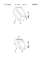
- FIG. 10 is a perspective view of an elliptical spacer in accordance with the present invention.
- FIG. 11 is a perspective view of a parallelogram-shaped spacer in accordance with the present invention.
- FIG. 12 is a side elevational view of a multiple ring well screen configuration in accordance with the present invention.
- FIG. 1 through FIG. 12 the apparatus generally shown in FIG. 1 through FIG. 12. It will be appreciated that the apparatus may vary as to configuration and as to details of the parts without departing from the basic concepts as disclosed herein.
- a well screen 10 in accordance with the present invention generally comprises a wire 12 spirally wound to form a porous cylinder.
- Wire 12 is wound with evenly spaced gaps 14 between the surfaces 18 of wire 12, with surfaces 18 of wire 12 attached by spacers 16 between the surfaces 18.
- Spacers 16 are positioned at intervals around the circumference of well screen 10 and do not extend radially from the inner edge 20 or the outer edge 22 of wire 12.
- An inner surface 24 and an outer surface 26 of well screen 10 is thereby formed.
- the "C" in FIG. 1 represents the central axis of well screen 10.
- spacers 16 are designed to minimize disruption of fluid flow along the horizontal axis by using a streamlined or elliptical design 50.
- the acute 52 or sharper end of spacer 16 is oriented towards outer edge 22 of wire 12, thus minimizing the surface area which restricts fluid flow at or near the entry point.
- spacer 16 width and thickness (volume) increases at a slightly slower rate than the greater volume of the widening gap 14 between surfaces 18 of wire 12.
- a greater net volume of the overall entrance chamber is created, thereby slowing fluid flow and causing less turbulence against entry.
- the outer or acute end 52 of spacer 16 does not extend to outer edge 22 of the wire 12, thus forming a recess 28 from outer surface 26 of well screen 10, as shown in FIG. 3.
- Recess 28 also aids in controlling corrosion as it reduces the fluid flow rate at that location which consequently reduces the occurrence of corrosion.
- acute end 52 of spacer 16 extends to outer edge 22 of wire 12, as shown in FIG. 4, giving well screen 10 extra strength and rigidity but reducing the amount of open area.
- the open area given up as a result of spacer 16 extending to outer edge 22 of wire 12 can be made up elsewhere, i.e. wider gaps 14 or fewer spacers 16.
- the number of spacers 16 between each layer of wire 12 varies according to structural, chemical, hydraulic and economic objectives.
- spacer 16 includes acute end 52 of spacer 16 extending to outer edge 22 of wire 12 and inner end 64 of spacer 16 recessed from inner edge 20 of wire 12 forming inner recess 66, as shown in FIG. 5. Yet another variation is to position spacer 16 such that its longitudinal axis L forms an acute angle ⁇ from a perpendicular P to a tangent to outer edge 22 of wire 12, as shown in FIG. 6.
- wire 12 is shown as a cold-rolled formation of a "Vee-shape" or trapezoidal-shape cross section 30 with the apex 32 of the "Vee” or trapezoid oriented towards inner surface 24 of well screen 10. Reducing the width profile (thickness) of the outer edge 22 of wire 12 results in a proportional increase in gap 14, which make up the fluid producing open areas. Because the apex 32 of wire 12 is oriented towards the inner surface 24 of the well screen 10, the volume of gap 14 between the layers of wire 12 increases towards the inner surface 24 of the well screen 10.
- the wire width to gap ratio is in the order of 1:2, with the gap 14 width (thickness) generally being twice the wire 12 width profile (thickness).
- wire 12 is preferably wound spirally at an angle up to approximately a 6° inclination as measured from the horizontal plane. It is also contemplated that wire 12 can have other cross-sectional shapes.
- the width of gap 14 between the surface 18 of wire 12 is variable depending upon the application of the well screen 10.
- the width is usually based on the relative size of the formation sand to be excluded. Where sands have a broad size distribution, a gap width of two times as large as the ten percentile diameter of the formation sand has been successfully used. Where sands are generally more uniform in size and rounded, a gap width equal to the ten to fifteen percentile formation sand diameter is used.
- spacers 16 are used during manufacturing which results in precisely formed apertures 54, thus allowing for accurate performance calculations and improved sand and particle filtration. Any length of spacer 16 can be used with any thickness of wire 12 and placed at any point along the wire surface 18 in any direction, thus allowing for optimal hydraulic, structural and chemical considerations.
- the variable circumferential position and spacer 16 shape can be used to benefit the hydraulic behavior of fluids while inside the confines of well screen 10, in the manner the fluids enter from the formation and in the manner which they are injected into the formation.
- the spacer system allows for precise connections between surface 18 of wire 12 by drawing them over a round mandrel or by placing them in a socket and fusion welding them in place.
- the result is a significantly reduced tubular ellipticity, an important consideration in conventional screen design as most failures occur due to collapse from elliptical induced weaknesses.
- Fillet welds 58 as shown in FIG. 7 and FIG. 8, around the joints of spacer 16 to wire 12 can further strengthen well screen 10 by reducing triangular stresses.
- spacers 16 can be positioned on the wire surface 18 mid-way above and below an aperture 54, which is formed by the surface boundaries of wire 12 and spacer 16 combination. This basically forms a diamond pattern which reduces leveraged stress across the wire.
- spacers 16 are positioned at intervals such that a portion of gaps 14 lie directly above and directly below each spacer 16. Therefore, the exact positioning of spacer 16 is driven by the direction and angle well screen 10 must be contorted.
- the flush inner surface 24 of the well screen 10 allows greater penetration of line scratching (vertical wire brushing) and rotary scratching (rotary brushing).
- line scratching vertical wire brushing
- rotary scratching rotary brushing
- An alternative spacer design in the form of a parallelogram 60 with curved corners 62, as shown in FIG. 11, allows both the initial sweep to be completed and subsequent entry and guiding of the same or new bristles into the next successive aperture, thus achieving a more thorough cleaning.
- spacers 16 could be of other shapes, including but not limited to, straight-edged, curved and curvilinear shapes. Spacer 16 could also be asymmetrically shaped such that a vortex is generated by the fluid entering well screen 10 to emulate natural whirling drainage patterns.
- the invention can be manufactured using a conventional secondary cold rolling process, resulting in greater precision of all aspects of the well screen 10. This process can be followed by a "bead blasting" polishing process, to reduce microscopic irregularities on the wire surface 18 that can contribute to the formation of hydraulic eddies, which are detrimental to smooth and efficient fluid flow. Both processes serve to increase the strength of the well screen 10.
- FIG. 12 illustrates an alternate embodiment of the invention wherein "C" represents the central axis of the ring well screen 34.
- Ring well screen 34 comprises a plurality of rings 36 vertically stacked and attached together by spacers 16 placed at intervals circumferentially on the surface 38 of rings 36.
- Rings 36 are formed by using a cold-rolled formation of a "Vee-shape" or trapezoidal-shape wire 30, as previously shown in FIG. 5, which has undergone an electro-resistance and pressure welding process to form a ring 36.
- Ring 36 has a generally trapezoidal cross section 30 with the apex 32 oriented towards the inner surface of well screen 34. All the other aspects of this ring well screen share a similarity to the wire well screen previously discussed.
- the invention herein can be fabricated from stainless steel, low carbon steel, plastic, polymers, carbon fiber, ceramics and other materials suitable for use in well environments. It will also be appreciated that the invention can be used as a drive point, strainer, filter, or other fluid porous media Although the description above contains many specificities, these should not be construed as limiting the scope of the invention but as merely providing illustrations of some of the presently preferred embodiments of this invention. Thus the scope of this invention should be determined by the appended claims and their legal equivalents.
Landscapes
- Chemical & Material Sciences (AREA)
- Chemical Kinetics & Catalysis (AREA)
- Mining & Mineral Resources (AREA)
- Life Sciences & Earth Sciences (AREA)
- Engineering & Computer Science (AREA)
- Geology (AREA)
- Fluid Mechanics (AREA)
- Environmental & Geological Engineering (AREA)
- Physics & Mathematics (AREA)
- General Life Sciences & Earth Sciences (AREA)
- Geochemistry & Mineralogy (AREA)
- Dispersion Chemistry (AREA)
- Filtration Of Liquid (AREA)
- Filtering Materials (AREA)
Abstract
A well screen for placement within wells used to filter out impurities from the fluid entering the well. In the preferred embodiment, the well screen comprises a spirally-wound wire forming a cylinder with gaps between the layers of wire. The layers of wire are attached by spacers placed within the gaps and on the surfaces of the wire such that the spacers do not extend radially beyond the inner and outer edges of the wire. The outer edge of the spacer can be flush or slightly recessed from the outer edge of the wire to create greater open area for which fluid can flow through. The inner edge of the spacer can also be flush or slightly recessed from the outer edge of the wire. In the alternate embodiment, the well screen comprises a plurality of rings stacked atop each other and connected together by spacers located at intervals around the circumference of the rings. The spacers are attached to the wire or rings by a secure means such as welding which results in a single unitized screen that is structurally rigid. The spacer/ring configuration allows greater open area on the screen which increases fluid flow and efficiency through the screen.
Description
This application is a continuation-in-part of copending application Ser. No. 08/904,883 filed on Aug. 1, 1997, now U.S. Pat. No. 5,785,122.
Not Applicable
Not Applicable
1. Field of the Invention
This invention pertains generally to well screens for oil, gas, mineral, and groundwater production, and groundwater monitoring, and more particularly to an improved one piece wire-wrapped well screen.
2. Description of the Background Art
When water, oil and gas producing wells are drilled through unconsolidated formations, the produced fluids generally contain particulate matter, usually sand. The production of sand, along with the fluids, is an undesired consequence because the sand causes extra wear and abrasion of production tubing, valves, pumps, and other equipment used to produce and remove fluids from the wells. It is therefore beneficial to avoid or minimize the production of sand or other particulate matter during the production of fluids from wells.
One method of accomplishing the reduction of sand or particulate production is by "gravel packing" the well during completion operations. Such gravel packing includes providing on the production conduit or tubular work string a slotted or ported cylindrically shaped member, generally known as well screens, which restricts the passage of particles into the interior of the conduit. For many years, well screens have been used in wells to permit fluid to flow through the screen and into the well while retaining sand and other particulate matter outside the well screen.
A common well screen design uses longitudinal supports tangentially welded to a helical band to produce a frame upon which strainer elements or inserts are attached. The strainer elements or inserts fill the gaps between the longitudinal and helical bars and serve to retain sand and other particulate matter. In such designs, the filtration screen is not self-supporting and is dependent on the frame for rigidity.
Other designs of well screens incorporate "projections" that are formed in a stack of rings and which protrude parallel to the longitudinal axis of the structure and perpendicular to the rings. This enables installers to adjust the gap between the rings during installation of the well screen. However, the projections do not provide structural rigidity to the screen and merely rest on the inner surface of the rings, thereby resulting in an undulated inner well screen surface.
Current screen design practice assumes a 1% ellipticity, which significantly reduces collapse strength and requires use of excess materials in order to achieve the desired resistance. The general tensile calculation for conventional wire wrap screens includes an approximate 30% welding de-rating effect due to welding of the wire or ring apex to the rod tangent, which is also a corrosion enhancer. Wire/rod screens have no torsional qualities. Corrosion, well construction defects, or manufacturing errors occasionally lead to holes or cracks in well casings or screens. One approach toward repair is to spot a serrated piece of slightly under-sized casing and hydraulically pressing this piece over the problem area, essentially forming a patch. This is impractical due to the presence of vertical rod protrusions in conventional wire wrap screens.
Conventional wire wrap screens normally show mostly steel, not open area available for fluid to flow through. The usual range of open area percentage exposed to abutting geological formations is 20%-50% with a fluid entrance efficiency of approximately 90% at best.
By way of example and not of limitation, the present invention is a well screen which generally comprises a wire which is spirally wound to form a cylinder with spaces between each layer of wire. Spacers between the wire at intervals around the circumference of the well screen serve to attach the layers of wire together. The spacers do not extend radially beyond the inner or outer edge of the wire. The spacers can be flush with either the inner and/or outer edge of the wire or recessed from either the inner and/or outer edge of the wire. The spacers are permanently and securely attached to the wire by means such as welding, resulting in a single unitized well screen that is also very structurally rigid.
In an alternate embodiment of the invention, the well screen comprises a plurality of rings stacked atop one another and connected together by spacers located at intervals around the circumference of the rings, generally forming a cylinder. The spacers do not extend radially beyond either the inner or outer edge of the rings. The spacers can be flush with either the inner and/or outer edge of the ring or recessed from either the inner and/or outer edge of the ring. The spacers are attached to the rings in the same manner as with the spiral wire well screen design.
This spacer/wire and spacer/ring design allows for fabrication and use of any thickness or width of wire or ring. By increasing wire or ring thickness and essentially melting the vertically oriented rod components of wire wrap screen into the thickness of the rings, and then welding these in place, superior strength is created even with less width profile. Since it is advantageous to provide more open area through which the fluid can enter the screen, aperture dimensions can be varied by adjusting ring thickness, width, spacer dimensions, spacer shapes, placement and orientation, in order to improve fluid flow therethrough, while simultaneously increasing strength and rigidity and reducing material requirements.
The spacer shape is variable, which allows the manipulation of fluid dynamics. Improved fluid flow characteristics can be achieved, thus increasing flow efficiency while reducing corrosion and plugging tendencies of conventional well screen designs.
Since the spacers do not extend beyond the inner surface of the well screen, the flush inner surface of the well screen also allows ready installation of "swaged" patches for damage repair and eases repair when fissures develop during use. The flush inner surface allows the use of zone isolation devices with greater effectiveness. The flush inner surface also allows rotation activities within the screen without interference or catching of rods on the rotating device which would otherwise damage or destroy the screen.
This design eliminates or minimizes problems associated with tangential welding and normal stress points as such welds are more robust and less susceptible to corrosion. In addition, any length of well screen can be easily manufactured because no rods are used.
An object of the invention is to provide a one-piece rigid well screen which is selfsupporting, has increased structural strength and which can be manufactured efficiently and reliably.
Another object of this invention is to provide a greater area through which fluid can flow, thus enhancing the fluid entrance capability and efficiency.
Yet another object of the invention is to provide for a flush inner and outer surface. The flush inner surface allows the well screen to be cleaned using techniques such as vertical wire brushing and rotary scratching.
Further objects and advantages of the invention will be brought out in the following portions of the specification, wherein the detailed description is for the purpose of fully disclosing preferred embodiments of the invention without placing limitations thereon.
The invention will be more fully understood by reference to the following drawings which are for illustrative purposes only:
FIG. 1 is a fragmentary side elevational view of a spiral wire well screen in accordance with the present invention.
FIG. 2 is a top view of the well screen showing the spacers angled.
FIG. 3 is top plan view of the preferred embodiment of a ring spacer in accordance with the present invention shown in relation to a fragment of a wire.
FIG. 4 is top plan view of a second embodiment of a ring spacer in accordance with the present invention shown in relation to a fragment of a wire.
FIG. 5 is top plan view of a third embodiment of a ring spacer in accordance with the present invention shown in relation to a fragment of a wire.
FIG. 6 is top plan view of a fourth embodiment of a ring spacer in accordance with the present invention shown in relation to a fragment of a wire.
FIG. 7 is a cross-sectional view of the well screen shown in FIG. 2 taken through line 7--7.
FIG. 8 is a fragmentary side elevation view of the well screen shown in FIG. 2 showing a spacer between two wires and fillet welds between the spacer and wires.
FIG. 9 is a fragmentary cross-sectional view in perspective of the well screen shown in FIG. 2 taken through line 9--9.
FIG. 10 is a perspective view of an elliptical spacer in accordance with the present invention.
FIG. 11 is a perspective view of a parallelogram-shaped spacer in accordance with the present invention.
FIG. 12 is a side elevational view of a multiple ring well screen configuration in accordance with the present invention.
Referring more specifically to the drawings, for illustrative purposes the present invention is embodied in the apparatus generally shown in FIG. 1 through FIG. 12. It will be appreciated that the apparatus may vary as to configuration and as to details of the parts without departing from the basic concepts as disclosed herein.
Referring first to FIG. 1 and FIG. 2, it will be seen that a well screen 10 in accordance with the present invention generally comprises a wire 12 spirally wound to form a porous cylinder. Wire 12 is wound with evenly spaced gaps 14 between the surfaces 18 of wire 12, with surfaces 18 of wire 12 attached by spacers 16 between the surfaces 18. Spacers 16 are positioned at intervals around the circumference of well screen 10 and do not extend radially from the inner edge 20 or the outer edge 22 of wire 12. An inner surface 24 and an outer surface 26 of well screen 10 is thereby formed. The "C" in FIG. 1 represents the central axis of well screen 10.
Referring also to FIG. 3 through FIG. 7, spacers 16 are designed to minimize disruption of fluid flow along the horizontal axis by using a streamlined or elliptical design 50. The acute 52 or sharper end of spacer 16 is oriented towards outer edge 22 of wire 12, thus minimizing the surface area which restricts fluid flow at or near the entry point. As spacer 16 approaches inner edge 20 of wire 12, spacer's 16 width and thickness (volume) increases at a slightly slower rate than the greater volume of the widening gap 14 between surfaces 18 of wire 12. Thus, a greater net volume of the overall entrance chamber is created, thereby slowing fluid flow and causing less turbulence against entry.
Preferably, the outer or acute end 52 of spacer 16 does not extend to outer edge 22 of the wire 12, thus forming a recess 28 from outer surface 26 of well screen 10, as shown in FIG. 3. This creates a greater open area and continuous opening through which fluid can flow through, thus enhancing fluid flow and efficiency. Recess 28 also aids in controlling corrosion as it reduces the fluid flow rate at that location which consequently reduces the occurrence of corrosion.
Alternatively, acute end 52 of spacer 16 extends to outer edge 22 of wire 12, as shown in FIG. 4, giving well screen 10 extra strength and rigidity but reducing the amount of open area. However, the open area given up as a result of spacer 16 extending to outer edge 22 of wire 12 can be made up elsewhere, i.e. wider gaps 14 or fewer spacers 16. The number of spacers 16 between each layer of wire 12 varies according to structural, chemical, hydraulic and economic objectives.
Another variation for spacer 16 includes acute end 52 of spacer 16 extending to outer edge 22 of wire 12 and inner end 64 of spacer 16 recessed from inner edge 20 of wire 12 forming inner recess 66, as shown in FIG. 5. Yet another variation is to position spacer 16 such that its longitudinal axis L forms an acute angle α from a perpendicular P to a tangent to outer edge 22 of wire 12, as shown in FIG. 6.
Referring also to FIG. 7 and FIG. 9, wire 12 is shown as a cold-rolled formation of a "Vee-shape" or trapezoidal-shape cross section 30 with the apex 32 of the "Vee" or trapezoid oriented towards inner surface 24 of well screen 10. Reducing the width profile (thickness) of the outer edge 22 of wire 12 results in a proportional increase in gap 14, which make up the fluid producing open areas. Because the apex 32 of wire 12 is oriented towards the inner surface 24 of the well screen 10, the volume of gap 14 between the layers of wire 12 increases towards the inner surface 24 of the well screen 10. Ideally, the wire width to gap ratio is in the order of 1:2, with the gap 14 width (thickness) generally being twice the wire 12 width profile (thickness). To relieve triangular stress, wire 12 is preferably wound spirally at an angle up to approximately a 6° inclination as measured from the horizontal plane. It is also contemplated that wire 12 can have other cross-sectional shapes.
The width of gap 14 between the surface 18 of wire 12 is variable depending upon the application of the well screen 10. The width is usually based on the relative size of the formation sand to be excluded. Where sands have a broad size distribution, a gap width of two times as large as the ten percentile diameter of the formation sand has been successfully used. Where sands are generally more uniform in size and rounded, a gap width equal to the ten to fifteen percentile formation sand diameter is used.
Identically fabricated spacers 16 are used during manufacturing which results in precisely formed apertures 54, thus allowing for accurate performance calculations and improved sand and particle filtration. Any length of spacer 16 can be used with any thickness of wire 12 and placed at any point along the wire surface 18 in any direction, thus allowing for optimal hydraulic, structural and chemical considerations. The variable circumferential position and spacer 16 shape can be used to benefit the hydraulic behavior of fluids while inside the confines of well screen 10, in the manner the fluids enter from the formation and in the manner which they are injected into the formation. There is a slight circulation loss that occurs as high volumes of water travel through the inner surface 24 from the outer surface 26 of well screen 10, however this circulation loss can be improved by introducing twists or reliefs to the fluid as it enters well screen 10 to emulate natural whirling drainage patterns. Theoretical radial flow patterns into wells are generally not possible due to geological imperfections so, to equalize entry potential, fluid is forced into more exposure to the more perfect area of artificial gravel pack by slightly twisting the fluid flow in a manner commensurate with turbine pumping activity. Also, injection at different rates can be beneficial for cleaning applications by creating diversion and vortices in the fluid flow. Since the spacer system comprises only two separate pieces, spacer 16 and wire 12, cleaner cuts on the inner surface 24 and outer surface 26 can be created, if necessary, during well fishing operations.
The spacer system allows for precise connections between surface 18 of wire 12 by drawing them over a round mandrel or by placing them in a socket and fusion welding them in place. The result is a significantly reduced tubular ellipticity, an important consideration in conventional screen design as most failures occur due to collapse from elliptical induced weaknesses. Fillet welds 58, as shown in FIG. 7 and FIG. 8, around the joints of spacer 16 to wire 12 can further strengthen well screen 10 by reducing triangular stresses. For even greater structural rigidity, spacers 16 can be positioned on the wire surface 18 mid-way above and below an aperture 54, which is formed by the surface boundaries of wire 12 and spacer 16 combination. This basically forms a diamond pattern which reduces leveraged stress across the wire. However, to allow for some flexibility of well screen 10, spacers 16 are positioned at intervals such that a portion of gaps 14 lie directly above and directly below each spacer 16. Therefore, the exact positioning of spacer 16 is driven by the direction and angle well screen 10 must be contorted.
The flush inner surface 24 of the well screen 10 allows greater penetration of line scratching (vertical wire brushing) and rotary scratching (rotary brushing). There is a geometric advantage formed during rotary brushing in that at the point of contact with inner rods, bristles are deflected away from the last portion of the sweep through the aperture area. An alternative spacer design in the form of a parallelogram 60 with curved corners 62, as shown in FIG. 11, allows both the initial sweep to be completed and subsequent entry and guiding of the same or new bristles into the next successive aperture, thus achieving a more thorough cleaning. It is also contemplated that spacers 16 could be of other shapes, including but not limited to, straight-edged, curved and curvilinear shapes. Spacer 16 could also be asymmetrically shaped such that a vortex is generated by the fluid entering well screen 10 to emulate natural whirling drainage patterns.
The invention can be manufactured using a conventional secondary cold rolling process, resulting in greater precision of all aspects of the well screen 10. This process can be followed by a "bead blasting" polishing process, to reduce microscopic irregularities on the wire surface 18 that can contribute to the formation of hydraulic eddies, which are detrimental to smooth and efficient fluid flow. Both processes serve to increase the strength of the well screen 10.
The ability to manipulate spacer 16 placement, shape, position, and quantity allows well screen 10 to flex to fit non-linear wells. There also exists the possibility to couple any length of the well screen assembly with swiveling couplings, thus allowing a high degree of directional change without the need for a manufacturing design change.
FIG. 12 illustrates an alternate embodiment of the invention wherein "C" represents the central axis of the ring well screen 34. Ring well screen 34 comprises a plurality of rings 36 vertically stacked and attached together by spacers 16 placed at intervals circumferentially on the surface 38 of rings 36. Rings 36 are formed by using a cold-rolled formation of a "Vee-shape" or trapezoidal-shape wire 30, as previously shown in FIG. 5, which has undergone an electro-resistance and pressure welding process to form a ring 36. Ring 36 has a generally trapezoidal cross section 30 with the apex 32 oriented towards the inner surface of well screen 34. All the other aspects of this ring well screen share a similarity to the wire well screen previously discussed.
Those skilled in the art will appreciate that the invention herein can be fabricated from stainless steel, low carbon steel, plastic, polymers, carbon fiber, ceramics and other materials suitable for use in well environments. It will also be appreciated that the invention can be used as a drive point, strainer, filter, or other fluid porous media Although the description above contains many specificities, these should not be construed as limiting the scope of the invention but as merely providing illustrations of some of the presently preferred embodiments of this invention. Thus the scope of this invention should be determined by the appended claims and their legal equivalents.
Claims (36)
1. A well screen, comprising:
(a) a wire wound spirally to form a porous cylinder having a plurality of spaced-apart windings, said cylinder including an outer surface and an inner surface;
(b) a plurality of individual spacers positioned within gaps between said windings and further positioned between said outer surface and said inner surface of said cylinder, said spacers including an inner edge and an outer edge, said inner edge and said outer edge defining a longitudinal axis therebetween of said spacers; and
(c) means for securely attaching said spacers to said windings.
2. An apparatus as recited in claim 1, wherein said inner edge of said spacer is flush with said inner surface of said cylinder, said outer edge of said spacer flush with said outer surface of said cylinder.
3. An apparatus as recited in claim 1, wherein said inner edge of said spacer is recessed from said inner surface of said cylinder, said outer edge of said spacer is flush with said outer surface of said cylinder.
4. An apparatus as recited in claim 1, wherein said inner edge of said spacer is recessed from said inner surface of said cylinder, said outer edge of said spacer is recessed from said outer surface of said cylinder.
5. An apparatus as recited in claim 1, wherein said longitudinal axis being generally perpendicular to a tangent of said windings between which said respective spacer is positioned.
6. An apparatus as recited in claim 1, wherein said spacers are positioned such that said longitudinal axis forms an acute angle from a perpendicular to a tangent to said windings between which said respective spacer is positioned.
7. An apparatus as recited in claim 1, wherein said spacers each having a width and a thickness, said width of each said spacer increasing as said spacer extends toward said inner surface of said cylinder, said thickness of said spacer increasing as said spacer extends toward said inner surface of said cylinder.
8. An apparatus as recited in claim 1, wherein each said spacer has an elliptical shape with an acute end and an obtuse end, said acute end of each said spacer oriented towards said outer surface of said cylinder.
9. An apparatus as recited in claim 1, wherein each said spacer is parallelogram-shaped with four curved corners.
10. An apparatus as recited in claim 1, wherein said wire has a trapezoidal cross-section having an apex oriented towards said inner surface of said cylinder.
11. An apparatus as recited in claim 1, wherein each said spacers are attached between said windings at intervals such that a portion of said gaps lie directly above and directly below each said spacer.
12. An apparatus as recited in claim 1, wherein each said spacers are shaped such that fluid passing through said gaps create a vortex.
13. A well screen, comprising:
(a) a wire wound spirally to form a porous cylinder having a plurality of spaced-apart windings, said cylinder including an outer surface and an inner surface; and
(b) a plurality of individual spacers welded between said windings, said spacers including an inner edge and an outer edge, said inner edge and said outer edge defining a longitudinal axis therebetween of said spacers;
(c) wherein each said spacers are attached between said windings at intervals such that a portion of said gaps lie directly above and directly below each said spacer.
14. An apparatus as recited in claim 13, wherein said inner edge of said spacer is flush with said inner surface of said cylinder, said outer edge of said spacer flush with said outer surface of said cylinder.
15. An apparatus as recited in claim 13, wherein said inner edge of said spacer is recessed from said inner surface of said cylinder, said outer edge of said spacer is flush with said outer surface of said cylinder.
16. An apparatus as recited in claim 13, wherein said inner edge of said spacer is recessed from said inner surface of said cylinder, said outer edge of said spacer is recessed from said outer surface of said cylinder.
17. An apparatus as recited in claim 13, wherein said longitudinal axis being generally perpendicular to a tangent of said windings between which said respective spacer is positioned.
18. An apparatus as recited in claim 13, wherein said spacers are positioned such that said longitudinal axis forms an acute angle from a perpendicular to a tangent to said windings between which said respective spacer is positioned.
19. An apparatus as recited in claim 13, wherein said spacers each having a width and a thickness, said width of each said spacer increasing as said spacer extends toward said inner surface of said cylinder, said thickness of said spacer increasing as said spacer extends toward said inner surface of said cylinder.
20. An apparatus as recited in claim 13, wherein each said spacer has an elliptical shape with an acute end and an obtuse end, said acute end of each said spacer oriented towards said outer surface of said cylinder.
21. An apparatus as recited in claim 13, wherein each said spacer is parallelogram-shaped with four curved corners.
22. An apparatus as recited in claim 13, wherein said wire has a trapezoidal cross-section having an apex oriented towards said inner surface of said cylinder.
23. An apparatus as recited in claim 13, wherein each said spacers are shaped such that fluid passing through said gaps create a vortex.
24. An apparatus as recited in claim 13, wherein each said spacers are attached between said windings at intervals such that a portion of said gaps lie directly above and directly below each said spacer.
25. A well screen, comprising:
(a) a plurality of concentric spaced-apart rings forming a porous cylinder, said cylinder including an outer surface and an inner surface;
(b) a plurality of individual spacers positioned in gaps between said rings, said spacers including an inner edge and an outer edge, said inner edge and said outer edge defining a longitudinal axis therebetween of said spacers; and
(c) means for securely attaching said spacers to said rings.
26. An apparatus as recited in claim 25, wherein said inner edge of said spacer is flush with said inner surface of said cylinder, said outer edge of said spacer flush with said outer surface of said cylinder.
27. An apparatus as recited in claim 25, wherein said inner edge of said spacer is recessed from said inner surface of said cylinder, said outer edge of said spacer is flush with said outer surface of said cylinder.
28. An apparatus as recited in claim 25, wherein said inner edge of said spacer is recessed from said inner surface of said cylinder, said outer edge of said spacer is recessed from said outer surface of said cylinder.
29. An apparatus as recited in claim 25, wherein said longitudinal axis being generally perpendicular to a tangent of said rings between which said respective spacer is positioned.
30. An apparatus as recited in claim 25, wherein said spacers are positioned such that said longitudinal axis forms an acute angle from a perpendicular to a tangent to said rings between which said respective spacer is positioned.
31. An apparatus as recited in claim 25, wherein said spacers each having a width and a thickness, said width of each said spacer increasing as said spacer extends toward said inner surface of said cylinder, said thickness of said spacer increasing as said spacer extends toward said inner surface of said cylinder.
32. An apparatus as recited in claim 25, wherein each said spacer has an elliptical shape with an acute end and an obtuse end, said acute end of each said spacer oriented towards said outer surface of said cylinder.
33. An apparatus as recited in claim 25, wherein each said spacer is parallelogram-shaped with four curved corners.
34. An apparatus as recited in claim 25, wherein said wire has a trapezoidal cross-section having an apex oriented towards said inner surface of said cylinder.
35. A well screen as recited in claim 25, wherein each said spacers are shaped such that fluid passing through said gaps create a vortex.
36. An apparatus as recited in claim 25, wherein each said spacers are attached between said windings at intervals such that a portion of said gaps lie directly above and directly below each said spacer.
Priority Applications (4)
| Application Number | Priority Date | Filing Date | Title |
|---|---|---|---|
| US09/123,197 US6089316A (en) | 1997-08-01 | 1998-07-27 | Wire-wrapped well screen |
| AU86059/98A AU8605998A (en) | 1997-08-01 | 1998-07-31 | Wire-wrapped well screen |
| PCT/US1998/016064 WO1999006669A1 (en) | 1997-08-01 | 1998-07-31 | Wire-wrapped well screen |
| US09/448,572 US6298914B1 (en) | 1997-08-01 | 1999-11-23 | Wire-wrapped well screen |
Applications Claiming Priority (2)
| Application Number | Priority Date | Filing Date | Title |
|---|---|---|---|
| US08/904,883 US5785122A (en) | 1997-08-01 | 1997-08-01 | Wire-wrapped well screen |
| US09/123,197 US6089316A (en) | 1997-08-01 | 1998-07-27 | Wire-wrapped well screen |
Related Parent Applications (1)
| Application Number | Title | Priority Date | Filing Date |
|---|---|---|---|
| US08/904,883 Continuation-In-Part US5785122A (en) | 1997-08-01 | 1997-08-01 | Wire-wrapped well screen |
Related Child Applications (1)
| Application Number | Title | Priority Date | Filing Date |
|---|---|---|---|
| US09/448,572 Continuation-In-Part US6298914B1 (en) | 1997-08-01 | 1999-11-23 | Wire-wrapped well screen |
Publications (1)
| Publication Number | Publication Date |
|---|---|
| US6089316A true US6089316A (en) | 2000-07-18 |
Family
ID=26821331
Family Applications (2)
| Application Number | Title | Priority Date | Filing Date |
|---|---|---|---|
| US09/123,197 Expired - Lifetime US6089316A (en) | 1997-08-01 | 1998-07-27 | Wire-wrapped well screen |
| US09/448,572 Expired - Fee Related US6298914B1 (en) | 1997-08-01 | 1999-11-23 | Wire-wrapped well screen |
Family Applications After (1)
| Application Number | Title | Priority Date | Filing Date |
|---|---|---|---|
| US09/448,572 Expired - Fee Related US6298914B1 (en) | 1997-08-01 | 1999-11-23 | Wire-wrapped well screen |
Country Status (3)
| Country | Link |
|---|---|
| US (2) | US6089316A (en) |
| AU (1) | AU8605998A (en) |
| WO (1) | WO1999006669A1 (en) |
Cited By (16)
| Publication number | Priority date | Publication date | Assignee | Title |
|---|---|---|---|---|
| US6298914B1 (en) * | 1997-08-01 | 2001-10-09 | Jeffery A. Spray | Wire-wrapped well screen |
| US20040026313A1 (en) * | 2002-08-09 | 2004-02-12 | Arlon Fischer Todd Kenneth | Multi-micron, multi-zoned mesh, method of making and use thereof |
| US6715544B2 (en) | 2000-09-29 | 2004-04-06 | Weatherford/Lamb, Inc. | Well screen |
| US6745843B2 (en) | 2001-01-23 | 2004-06-08 | Schlumberger Technology Corporation | Base-pipe flow control mechanism |
| WO2005021931A1 (en) | 2003-08-25 | 2005-03-10 | Spray Jeffery A | Expandable tubulars for use in geologic structures, methods for expanding tubulars, and methods of manufacturing expandable tubulars |
| US20070110598A1 (en) * | 2005-11-17 | 2007-05-17 | Jacobs Christopher A | System and method for pumping fluids |
| US20070199889A1 (en) * | 2006-02-27 | 2007-08-30 | Ruediger Tueshaus | Tubular filter material assemblies and methods |
| US20070199973A1 (en) * | 2006-02-27 | 2007-08-30 | Ruediger Tueshaus | Tubular filter material machine and methods |
| US20090133874A1 (en) * | 2005-09-30 | 2009-05-28 | Dale Bruce A | Wellbore Apparatus and Method for Completion, Production and Injection |
| US20090211965A1 (en) * | 2008-02-21 | 2009-08-27 | Weatherford/Lamb, Inc. | Arrangement for splicing panels together to form a cylindrical screen |
| US20100252250A1 (en) * | 2009-04-07 | 2010-10-07 | Halliburton Energy Services, Inc. | Well Screens Constructed Utilizing Pre-Formed Annular Elements |
| US9023456B2 (en) | 2011-03-18 | 2015-05-05 | Bilfinger Water Technologies, Inc. | Profiled wire screen for process flow and other applications |
| USD846161S1 (en) * | 2015-10-26 | 2019-04-16 | Aqseptence Group Pty Ltd. | Wire grating structure |
| CN109973056A (en) * | 2019-04-28 | 2019-07-05 | 朔创(厦门)科技有限公司 | A kind of wire-wrapped screen and wire-wrapped screen molding machine |
| USD1056259S1 (en) * | 2023-02-14 | 2024-12-31 | Franz Neuhofer | Structural panel |
| USD1107265S1 (en) | 2023-02-14 | 2025-12-23 | Franz Neuhofer | Structural panel |
Families Citing this family (7)
| Publication number | Priority date | Publication date | Assignee | Title |
|---|---|---|---|---|
| US7281319B1 (en) | 2004-04-30 | 2007-10-16 | Daniel Allford | Apparatus for manufacturing wire wound filter screens |
| US7753121B2 (en) * | 2006-04-28 | 2010-07-13 | Schlumberger Technology Corporation | Well completion system having perforating charges integrated with a spirally wrapped screen |
| EP1983153A1 (en) * | 2007-04-17 | 2008-10-22 | PRAD Research and Development N.V. | Flexible liner for drilled drainhole deployment |
| EP2662124B1 (en) * | 2009-07-20 | 2016-11-09 | 3M Innovative Properties Company | Separation apparatus for tubular throughflow apparatuses |
| BR112012024771B1 (en) * | 2010-03-31 | 2019-07-02 | 3M Innovative Properties Company | SEPARATION DEVICE FOR SEPARATION OF SAND AND ROCK PARTICULARS AND USE OF SUCH SEPARATION DEVICE |
| GB201215801D0 (en) * | 2012-09-05 | 2012-10-24 | Optima Internat Ltd | Apparatus and method for forming screens |
| RU2586359C1 (en) * | 2015-04-17 | 2016-06-10 | Валентин Петрович Ткаченко | Well filter of improved permeability |
Citations (13)
| Publication number | Priority date | Publication date | Assignee | Title |
|---|---|---|---|---|
| US880635A (en) * | 1905-11-17 | 1908-03-03 | Harry R Decker | Oil and water well strainer. |
| US1273236A (en) * | 1916-10-23 | 1918-07-23 | Mahlon E Layne | Well-screen. |
| CH496877A (en) * | 1968-09-02 | 1970-09-30 | Fehlmann Grundwasserbauten Ag | Filter tube consisting of several partial lengths and provided with slotted holes |
| US3584685A (en) * | 1968-12-30 | 1971-06-15 | Universal Oil Prod Co | Tubular screen |
| US3712373A (en) * | 1970-10-02 | 1973-01-23 | Pan American Petroleum Corp | Multi-layer well screen |
| GB1400673A (en) * | 1973-04-07 | 1975-07-23 | Reijonen Y | Straining tube for lined ground-water well |
| US4299283A (en) * | 1980-06-26 | 1981-11-10 | Reese Enterprises, Inc. | Strip structure for well screen |
| US4381820A (en) * | 1981-12-24 | 1983-05-03 | Uop Inc. | Filament reinforced plastic screen and apparatus for making same |
| DE3913986A1 (en) * | 1988-04-28 | 1989-11-09 | Borsod Abauj Zemplen Megyei Vi | FILTER ELEMENT |
| US5095990A (en) * | 1990-10-26 | 1992-03-17 | Mobil Oil Corporation | Method and device for sand control |
| EP0617195A2 (en) * | 1993-03-22 | 1994-09-28 | Halliburton Company | Well completion apparatus |
| US5355949A (en) * | 1993-04-22 | 1994-10-18 | Sparlin Derry D | Well liner with dual concentric half screens |
| US5785122A (en) * | 1997-08-01 | 1998-07-28 | Spray; Jeffrey A. | Wire-wrapped well screen |
Family Cites Families (11)
| Publication number | Priority date | Publication date | Assignee | Title |
|---|---|---|---|---|
| US1367406A (en) | 1920-03-01 | 1921-02-01 | Mclean Marrs | Well-screen |
| US1715856A (en) | 1927-01-28 | 1929-06-04 | Jr Joseph Henry Mcevoy | Well screen |
| US2155744A (en) | 1936-06-23 | 1939-04-25 | Leslie A Layne | Well strainer |
| US2346647A (en) | 1940-11-28 | 1944-04-18 | Edward E Johnson Inc | Well screen |
| AT320535B (en) | 1971-06-17 | 1975-02-10 | Fl Upo Osakeyhtioe | Well filter |
| US4167972A (en) | 1977-12-23 | 1979-09-18 | Uop Inc. | Well screen mounting arrangement |
| US5115864A (en) | 1988-10-05 | 1992-05-26 | Baker Hughes Incorporated | Gravel pack screen having retention means and fluid permeable particulate solids |
| JP2891582B2 (en) | 1991-12-27 | 1999-05-17 | 株式会社ナガオカ | Method of manufacturing selective isolation screen |
| US5355948A (en) | 1992-11-04 | 1994-10-18 | Sparlin Derry D | Permeable isolation sectioned screen |
| SE501110C2 (en) | 1993-04-21 | 1994-11-14 | Kvaerner Pulping Tech | Screening means with a screen body and method and apparatus for the screen body manufacture |
| US6089316A (en) * | 1997-08-01 | 2000-07-18 | Spray; Jeffery A. | Wire-wrapped well screen |
-
1998
- 1998-07-27 US US09/123,197 patent/US6089316A/en not_active Expired - Lifetime
- 1998-07-31 WO PCT/US1998/016064 patent/WO1999006669A1/en not_active Ceased
- 1998-07-31 AU AU86059/98A patent/AU8605998A/en not_active Abandoned
-
1999
- 1999-11-23 US US09/448,572 patent/US6298914B1/en not_active Expired - Fee Related
Patent Citations (13)
| Publication number | Priority date | Publication date | Assignee | Title |
|---|---|---|---|---|
| US880635A (en) * | 1905-11-17 | 1908-03-03 | Harry R Decker | Oil and water well strainer. |
| US1273236A (en) * | 1916-10-23 | 1918-07-23 | Mahlon E Layne | Well-screen. |
| CH496877A (en) * | 1968-09-02 | 1970-09-30 | Fehlmann Grundwasserbauten Ag | Filter tube consisting of several partial lengths and provided with slotted holes |
| US3584685A (en) * | 1968-12-30 | 1971-06-15 | Universal Oil Prod Co | Tubular screen |
| US3712373A (en) * | 1970-10-02 | 1973-01-23 | Pan American Petroleum Corp | Multi-layer well screen |
| GB1400673A (en) * | 1973-04-07 | 1975-07-23 | Reijonen Y | Straining tube for lined ground-water well |
| US4299283A (en) * | 1980-06-26 | 1981-11-10 | Reese Enterprises, Inc. | Strip structure for well screen |
| US4381820A (en) * | 1981-12-24 | 1983-05-03 | Uop Inc. | Filament reinforced plastic screen and apparatus for making same |
| DE3913986A1 (en) * | 1988-04-28 | 1989-11-09 | Borsod Abauj Zemplen Megyei Vi | FILTER ELEMENT |
| US5095990A (en) * | 1990-10-26 | 1992-03-17 | Mobil Oil Corporation | Method and device for sand control |
| EP0617195A2 (en) * | 1993-03-22 | 1994-09-28 | Halliburton Company | Well completion apparatus |
| US5355949A (en) * | 1993-04-22 | 1994-10-18 | Sparlin Derry D | Well liner with dual concentric half screens |
| US5785122A (en) * | 1997-08-01 | 1998-07-28 | Spray; Jeffrey A. | Wire-wrapped well screen |
Cited By (27)
| Publication number | Priority date | Publication date | Assignee | Title |
|---|---|---|---|---|
| US6298914B1 (en) * | 1997-08-01 | 2001-10-09 | Jeffery A. Spray | Wire-wrapped well screen |
| US6715544B2 (en) | 2000-09-29 | 2004-04-06 | Weatherford/Lamb, Inc. | Well screen |
| US6745843B2 (en) | 2001-01-23 | 2004-06-08 | Schlumberger Technology Corporation | Base-pipe flow control mechanism |
| US20040026313A1 (en) * | 2002-08-09 | 2004-02-12 | Arlon Fischer Todd Kenneth | Multi-micron, multi-zoned mesh, method of making and use thereof |
| WO2005021931A1 (en) | 2003-08-25 | 2005-03-10 | Spray Jeffery A | Expandable tubulars for use in geologic structures, methods for expanding tubulars, and methods of manufacturing expandable tubulars |
| US20050109517A1 (en) * | 2003-08-25 | 2005-05-26 | Spray Jeffrey A. | Expandable tubulars for use in geologic structures, methods for expanding tubulars, and methods of manufacturing expandable tubulars |
| US7677321B2 (en) | 2003-08-25 | 2010-03-16 | Dynamic Tubular Systems, Inc. | Expandable tubulars for use in geologic structures, methods for expanding tubulars, and methods of manufacturing expandable tubulars |
| US20090133874A1 (en) * | 2005-09-30 | 2009-05-28 | Dale Bruce A | Wellbore Apparatus and Method for Completion, Production and Injection |
| US7891420B2 (en) | 2005-09-30 | 2011-02-22 | Exxonmobil Upstream Research Company | Wellbore apparatus and method for completion, production and injection |
| US20070110598A1 (en) * | 2005-11-17 | 2007-05-17 | Jacobs Christopher A | System and method for pumping fluids |
| US7413009B2 (en) | 2005-11-17 | 2008-08-19 | Henry Research And Development Llc | System and method for pumping fluids |
| US20070199973A1 (en) * | 2006-02-27 | 2007-08-30 | Ruediger Tueshaus | Tubular filter material machine and methods |
| US20070199889A1 (en) * | 2006-02-27 | 2007-08-30 | Ruediger Tueshaus | Tubular filter material assemblies and methods |
| US20090211965A1 (en) * | 2008-02-21 | 2009-08-27 | Weatherford/Lamb, Inc. | Arrangement for splicing panels together to form a cylindrical screen |
| US20100252250A1 (en) * | 2009-04-07 | 2010-10-07 | Halliburton Energy Services, Inc. | Well Screens Constructed Utilizing Pre-Formed Annular Elements |
| US8196653B2 (en) | 2009-04-07 | 2012-06-12 | Halliburton Energy Services, Inc. | Well screens constructed utilizing pre-formed annular elements |
| US8302681B2 (en) | 2009-04-07 | 2012-11-06 | Halliburton Energy Services, Inc. | Well screens constructed utilizing pre-formed annular elements |
| US9023456B2 (en) | 2011-03-18 | 2015-05-05 | Bilfinger Water Technologies, Inc. | Profiled wire screen for process flow and other applications |
| USD846161S1 (en) * | 2015-10-26 | 2019-04-16 | Aqseptence Group Pty Ltd. | Wire grating structure |
| USD921935S1 (en) | 2015-10-26 | 2021-06-08 | Aqseptence Group Pty Ltd. | Wire grating structure |
| USD951490S1 (en) | 2015-10-26 | 2022-05-10 | Aqseptence Group Pty Ltd. | Wire grating structure |
| USD951491S1 (en) | 2015-10-26 | 2022-05-10 | Aqseptence Group Pty Ltd. | Wire grating structure |
| USD952194S1 (en) | 2015-10-26 | 2022-05-17 | Aqseptence Group Pty Ltd. | Wire grating structure |
| CN109973056A (en) * | 2019-04-28 | 2019-07-05 | 朔创(厦门)科技有限公司 | A kind of wire-wrapped screen and wire-wrapped screen molding machine |
| CN109973056B (en) * | 2019-04-28 | 2024-04-09 | 朔创(厦门)科技有限公司 | Wire-wrapped screen pipe and wire-wrapped screen pipe forming device |
| USD1056259S1 (en) * | 2023-02-14 | 2024-12-31 | Franz Neuhofer | Structural panel |
| USD1107265S1 (en) | 2023-02-14 | 2025-12-23 | Franz Neuhofer | Structural panel |
Also Published As
| Publication number | Publication date |
|---|---|
| AU8605998A (en) | 1999-02-22 |
| US6298914B1 (en) | 2001-10-09 |
| WO1999006669A1 (en) | 1999-02-11 |
Similar Documents
| Publication | Publication Date | Title |
|---|---|---|
| US6089316A (en) | Wire-wrapped well screen | |
| US5785122A (en) | Wire-wrapped well screen | |
| US4204967A (en) | Tubewell screen filters | |
| CA2421765C (en) | Well screen with spirally wrapped wire | |
| EP1206624B1 (en) | Well screen having an internal alternate flowpath | |
| CN102365421B (en) | There is the well screen assembly of many gage wires winding layer | |
| US5004049A (en) | Low profile dual screen prepack | |
| US6006829A (en) | Filter for subterranean use | |
| EP1015092B1 (en) | Well casing assembly with erosion protection for inner screen | |
| KR890003088B1 (en) | Deep well screen | |
| CN1075154C (en) | Coilable oil well screen pipe | |
| CN205154113U (en) | A sand control strainer for sandstone stratum deep well | |
| EP0819831A1 (en) | Screen for use in a well | |
| GB1598502A (en) | Protected well screen | |
| EP1117874A1 (en) | Flow modifier for submerged intake screen | |
| US5083614A (en) | Flexible gravel prepack production system for wells having high dog-leg severity | |
| US20050034860A1 (en) | Screen for sand control in a wellbore | |
| US10781673B2 (en) | Base pipes for sand control screen assemblies | |
| CA2850616A1 (en) | Screen assembly and methods of use | |
| WO2000047867A1 (en) | Sandfilter device for use in the recovery of oil, gas and water | |
| US10914141B2 (en) | Screen jacket termination configuration and method | |
| CN115012884A (en) | Multi-stage sand control screen | |
| RU2834823C1 (en) | Downhole anti-sand filter | |
| US1635368A (en) | Guarded opening screen | |
| US7032665B1 (en) | System and method for gravel packaging a well |
Legal Events
| Date | Code | Title | Description |
|---|---|---|---|
| STCF | Information on status: patent grant |
Free format text: PATENTED CASE |
|
| FPAY | Fee payment |
Year of fee payment: 4 |
|
| REMI | Maintenance fee reminder mailed | ||
| FPAY | Fee payment |
Year of fee payment: 8 |
|
| SULP | Surcharge for late payment |
Year of fee payment: 7 |
|
| FEPP | Fee payment procedure |
Free format text: PETITION RELATED TO MAINTENANCE FEES GRANTED (ORIGINAL EVENT CODE: PMFG); ENTITY STATUS OF PATENT OWNER: SMALL ENTITY Free format text: PETITION RELATED TO MAINTENANCE FEES FILED (ORIGINAL EVENT CODE: PMFP); ENTITY STATUS OF PATENT OWNER: SMALL ENTITY |
|
| REMI | Maintenance fee reminder mailed | ||
| PRDP | Patent reinstated due to the acceptance of a late maintenance fee |
Effective date: 20120807 |
|
| FPAY | Fee payment |
Year of fee payment: 12 |
|
| SULP | Surcharge for late payment |