US6081646A - In-line solder seal for optical fiber - Google Patents
In-line solder seal for optical fiber Download PDFInfo
- Publication number
- US6081646A US6081646A US08/863,432 US86343297A US6081646A US 6081646 A US6081646 A US 6081646A US 86343297 A US86343297 A US 86343297A US 6081646 A US6081646 A US 6081646A
- Authority
- US
- United States
- Prior art keywords
- optical fiber
- tube
- hermetic seal
- recited
- stripped
- Prior art date
- Legal status (The legal status is an assumption and is not a legal conclusion. Google has not performed a legal analysis and makes no representation as to the accuracy of the status listed.)
- Expired - Lifetime
Links
- 239000013307 optical fiber Substances 0.000 title claims abstract description 67
- 229910000679 solder Inorganic materials 0.000 title claims description 45
- 238000007789 sealing Methods 0.000 claims abstract description 12
- 238000005476 soldering Methods 0.000 claims abstract description 12
- 239000004593 Epoxy Substances 0.000 claims description 8
- 229910000833 kovar Inorganic materials 0.000 claims description 3
- 229910052745 lead Inorganic materials 0.000 claims description 3
- 229910052718 tin Inorganic materials 0.000 claims description 3
- 230000003287 optical effect Effects 0.000 description 7
- PXHVJJICTQNCMI-UHFFFAOYSA-N Nickel Chemical compound [Ni] PXHVJJICTQNCMI-UHFFFAOYSA-N 0.000 description 6
- PCHJSUWPFVWCPO-UHFFFAOYSA-N gold Chemical group [Au] PCHJSUWPFVWCPO-UHFFFAOYSA-N 0.000 description 4
- 229910052751 metal Inorganic materials 0.000 description 4
- 239000002184 metal Substances 0.000 description 4
- 239000000243 solution Substances 0.000 description 4
- 229910052737 gold Inorganic materials 0.000 description 3
- 239000010931 gold Substances 0.000 description 3
- 238000003780 insertion Methods 0.000 description 3
- 230000037431 insertion Effects 0.000 description 3
- 229910052759 nickel Inorganic materials 0.000 description 3
- 238000007747 plating Methods 0.000 description 3
- 230000005540 biological transmission Effects 0.000 description 2
- 238000004140 cleaning Methods 0.000 description 2
- 238000004891 communication Methods 0.000 description 2
- 230000007613 environmental effect Effects 0.000 description 2
- 239000011521 glass Substances 0.000 description 2
- 238000012423 maintenance Methods 0.000 description 2
- 238000000034 method Methods 0.000 description 2
- 238000012986 modification Methods 0.000 description 2
- 230000004048 modification Effects 0.000 description 2
- 238000004806 packaging method and process Methods 0.000 description 2
- 230000001681 protective effect Effects 0.000 description 2
- 206010070834 Sensitisation Diseases 0.000 description 1
- 239000007864 aqueous solution Substances 0.000 description 1
- QVGXLLKOCUKJST-UHFFFAOYSA-N atomic oxygen Chemical compound [O] QVGXLLKOCUKJST-UHFFFAOYSA-N 0.000 description 1
- 238000005452 bending Methods 0.000 description 1
- 230000006866 deterioration Effects 0.000 description 1
- 238000007598 dipping method Methods 0.000 description 1
- 239000000835 fiber Substances 0.000 description 1
- 230000004907 flux Effects 0.000 description 1
- 238000002347 injection Methods 0.000 description 1
- 239000007924 injection Substances 0.000 description 1
- 238000007689 inspection Methods 0.000 description 1
- 238000004519 manufacturing process Methods 0.000 description 1
- 239000000463 material Substances 0.000 description 1
- 238000001465 metallisation Methods 0.000 description 1
- 239000000203 mixture Substances 0.000 description 1
- 229910052760 oxygen Inorganic materials 0.000 description 1
- 239000001301 oxygen Substances 0.000 description 1
- PIBWKRNGBLPSSY-UHFFFAOYSA-L palladium(II) chloride Chemical compound Cl[Pd]Cl PIBWKRNGBLPSSY-UHFFFAOYSA-L 0.000 description 1
- 230000008313 sensitization Effects 0.000 description 1
- ANOBYBYXJXCGBS-UHFFFAOYSA-L stannous fluoride Chemical compound F[Sn]F ANOBYBYXJXCGBS-UHFFFAOYSA-L 0.000 description 1
- 229960002799 stannous fluoride Drugs 0.000 description 1
Images
Classifications
-
- G—PHYSICS
- G02—OPTICS
- G02B—OPTICAL ELEMENTS, SYSTEMS OR APPARATUS
- G02B6/00—Light guides; Structural details of arrangements comprising light guides and other optical elements, e.g. couplings
- G02B6/24—Coupling light guides
- G02B6/42—Coupling light guides with opto-electronic elements
- G02B6/4201—Packages, e.g. shape, construction, internal or external details
- G02B6/4248—Feed-through connections for the hermetical passage of fibres through a package wall
Definitions
- This invention relates to packaging optical fibers, and more particularly to hermetically sealing an optical fiber to a metal housing.
- Optical communication systems are desirable because of the wide bandwidths available for the information signal channels.
- the robustness of an optical fiber is increasingly important with increasing bandwidth capability.
- Lightwave repeaters, regenerators and optical amplifiers extend transmission distances of light signals. Inserted into a fiber system at a point where the original light signal becomes weak, they generate a stronger signal, effectively extending the operating distances. Repeaters and regenerators convert the light signal into an electrical signal before amplifying the signal. Optical amplifiers directly amplify the light signal. It is desirable to hermetically seal the repeaters, regenerators, optical amplifiers and other devices within a housing to prevent deterioration due to atmospheric conditions. This is particularly necessary for buried terrestrial or submarine optical fiber systems. The fact that the optical fiber cores have a very small diameter (typically 8 to 9 ⁇ m) makes them susceptible to damage and difficult to handle.
- U.S. Pat. No. 4,119,363 entitled "Package For Optical Devices Including Optical Fiber-To-Metal Hermetic Seal", issued on Oct. 10, 1978 to Irfan Camlibel et al, discloses an optical fiber that is hermetically sealed to a metal housing, where solder filling a thin walled metal tube forms a hermetic seal. The end of the optical fiber that is inserted into the tube is stripped to the bare optical fiber.
- a bare optical fiber, stripped of its protective outer cover is particularly vulnerable to damage during manufacturing, assembly, maintenance and operation. This vulnerability reduces yields, increases failures and raises the cost of operation and maintenance of an optical fiber system. The robustness of an optical fiber is increasingly important with increasing bandwidth capability.
- the present invention is an in-line hermetic seal for an optical fiber.
- the optical fiber has an outer diameter and a stripped mid-section.
- a tube has an interior with a diameter larger than the outer diameter of the optical fiber and has an opening through a wall of the tube to the interior.
- the tube and the optical fiber having the stripped mid-section extending through the tube define an annular space therebetween.
- Soldering means fills the annular space. Sealing means holds the optical fiber approximately centered in ends of the tube.
- the stripped mid-section is contained by the tube, the sealing means and the soldering means. A method in accordance with the present invention is also described.
- FIG. 1 shows a prior art optical fiber hermetic solder seal
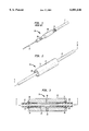
- FIG. 2 shows the in-line solder seal with an optical fiber
- FIG. 3 shows a longitudinal cross section A--A of the in-line solder seal.
- FIG. 1 there is shown a detail of a prior art optical fiber hermetic solder seal 10 which is presently used in commercial practice.
- the optical fiber 12 is stripped on one end to expose the bare optical fiber 14.
- the bare optical fiber 14 is inserted into a hollow solder seal tube 16.
- the hollow solder seal tube 16 is filled with solder through a first opening 18.
- solder may be wicked into the hollow solder seal tube 16 from the bare optical fiber 14 end.
- the assembly is permitted to cool so that the solder forms a hermetic seal.
- a second opening 19 permits inspection during assembly and after cleaning is utilized for the injection of epoxy between the optical fiber 12 and the interior of the hollow solder seal tube 16.
- the prior art optical fiber hermetic solder seal 10 may then be suitably attached to a housing.
- the bare optical fiber 14 which protrudes from the hollow solder seal tube 16 is exposed and thus highly susceptible to mechanical and environmental damage.
- FIG. 3 is a longitudinal cross section A--A of the optical fiber in-line solder seal 20 with the same components being assigned the same number.
- An optical fiber 22 with a stripped mid-section 24 (the protective covering having been removed exposing the inner glass optical fiber) is axially aligned within an in-line hollow solder seal tube 26.
- the in-line hollow solder seal tube 26 is typically made of a material such as Kovar, which is selected for its thermal expansion characteristics.
- the in-line hollow solder seal tube 26 has an interior diameter sufficiently large to permit the unstripped end of the optical fiber 22 to be inserted.
- the in-line hollow solder seal tube 26 has a fill opening 28 through the wall into the interior. Optionally an additional fill opening similar to fill opening 28 may be present.
- the interior of the in-line hollow solder seal tube 26 has tapered ends 30. Epoxy plugs 32 are at the ends of the in-line hollow solder seal tube 26 and hold the optical fiber 22.
- the interior cavity defined by the in-line hollow solder seal tube 26, optical fiber 22 and the epoxy plugs 32 contains solder.
- the interior mid-section of the in-line hollow solder tube 26 can have a larger diameter than the ends.
- the solder can be approximately 60% Sn and 40% Pb or other suitable composition.
- the optical fiber 22 is stripped in the mid-section 24 by bending the optical fiber 22 into a U shape and dipping the U shape into a stripping solution. The stripping solution then removes the outer layer of the optical fiber which exposes a section of the bare optical fiber.
- the optical fiber 22 with the stripped mid-section 24 is straightened from the U shape after stripping and is plated with nickel and gold. The optical fiber 22 must be straight when plated otherwise the plating may crack and be damaged. The plating covers the stripped mid-section 24 and over laps slightly beyond in order to ensure that there is no bare glass exposed.
- the optical fiber 22 is inserted into the in-line hollow solder seal tube 26 such that the stripped mid-section 24, which is now plated, is aligned to be contained within the in-line hollow solder seal tube 26.
- the tapered ends 30 of the interior of the in-line hollow solder seal tube 26 assist in the insertion of the optical fiber 22.
- Heat sinks may be attached to the ends of the in-line hollow solder seal tube 26 which will limit the flow of the solder.
- the interior mid-section of the in-line hollow solder tube 26 can have a larger diameter than the ends in order to assist in controlling the flow of the solder.
- An interior cavity, which is annular, is defined by the in-line hollow solder seal tube 26 and the optical fiber 22.
- the annular interior cavity is filled with solder through fill the opening(s) 28.
- the assembly is permitted to cool so that the solder forms a hermetic seal.
- epoxy plugs 32 are inserted into the ends of the in-line hollow solder seal tube 26 so as to fill the gap between the optical fiber 22 and the interior wall of the in-line hollow solder seal tube 26.
- the optical fiber in-line solder seal 20 may then be suitably attached to a housing.
- the insertion of the optical fiber 22 through the in-line hollow solder seal tube 26, filling with solder and insertion of the epoxy plugs 28 takes place at a location suitably isolated so that there is no danger of the stripping, plating, epoxy application, soldering or fluxing contaminating critical optical devices.
- optical fiber 22 which protrudes from the in-line hollow solder seal tube 26 does not have exposed a bare optical fiber which is highly susceptible to mechanical and environmental damage.
Landscapes
- Physics & Mathematics (AREA)
- General Physics & Mathematics (AREA)
- Optics & Photonics (AREA)
- Light Guides In General And Applications Therefor (AREA)
- Optical Couplings Of Light Guides (AREA)
Abstract
Description
Claims (15)
Priority Applications (2)
| Application Number | Priority Date | Filing Date | Title |
|---|---|---|---|
| US08/863,432 US6081646A (en) | 1997-05-27 | 1997-05-27 | In-line solder seal for optical fiber |
| US09/160,315 US6088504A (en) | 1997-05-27 | 1998-09-25 | In-line solder seal for optical fiber |
Applications Claiming Priority (1)
| Application Number | Priority Date | Filing Date | Title |
|---|---|---|---|
| US08/863,432 US6081646A (en) | 1997-05-27 | 1997-05-27 | In-line solder seal for optical fiber |
Related Child Applications (1)
| Application Number | Title | Priority Date | Filing Date |
|---|---|---|---|
| US09/160,315 Division US6088504A (en) | 1997-05-27 | 1998-09-25 | In-line solder seal for optical fiber |
Publications (1)
| Publication Number | Publication Date |
|---|---|
| US6081646A true US6081646A (en) | 2000-06-27 |
Family
ID=25341081
Family Applications (2)
| Application Number | Title | Priority Date | Filing Date |
|---|---|---|---|
| US08/863,432 Expired - Lifetime US6081646A (en) | 1997-05-27 | 1997-05-27 | In-line solder seal for optical fiber |
| US09/160,315 Expired - Fee Related US6088504A (en) | 1997-05-27 | 1998-09-25 | In-line solder seal for optical fiber |
Family Applications After (1)
| Application Number | Title | Priority Date | Filing Date |
|---|---|---|---|
| US09/160,315 Expired - Fee Related US6088504A (en) | 1997-05-27 | 1998-09-25 | In-line solder seal for optical fiber |
Country Status (1)
| Country | Link |
|---|---|
| US (2) | US6081646A (en) |
Cited By (3)
| Publication number | Priority date | Publication date | Assignee | Title |
|---|---|---|---|---|
| US20020179683A1 (en) * | 2001-06-01 | 2002-12-05 | Carrier Geary R. | Hermetic optical fiber seal |
| US6612752B2 (en) * | 1998-12-29 | 2003-09-02 | Corning Oti Spa | Sealed container for optical components and sealed feedthrough for optical fibers |
| CN114077014A (en) * | 2020-08-17 | 2022-02-22 | 华为机器有限公司 | Optical fiber sealing junction, wavelength selection switch, circuit board and communication equipment |
Families Citing this family (15)
| Publication number | Priority date | Publication date | Assignee | Title |
|---|---|---|---|---|
| IL128450A (en) * | 1999-02-09 | 2002-05-23 | Elop Electrooptics Ind Ltd | Method of bonding an optical element within an enclosure |
| US6526212B1 (en) * | 2000-07-28 | 2003-02-25 | Weatherford/Lamb, Inc. | Optical fiber bulkhead feedthrough assembly and method of making same |
| US6445868B1 (en) * | 2000-07-28 | 2002-09-03 | Weatherford/Lamb, Inc. | Optical fiber feedthrough assembly and method of making same |
| US6572743B2 (en) * | 2001-08-23 | 2003-06-03 | 3M Innovative Properties Company | Electroplating assembly for metal plated optical fibers |
| US6643446B2 (en) | 2001-11-27 | 2003-11-04 | Jds Uniphase Inc. | Hermetic fiber ferrule and feedthrough |
| US20030190135A1 (en) * | 2002-04-03 | 2003-10-09 | Moidu Abdul Jaleel J. | Hermetic waveguide seals and method of making them |
| US6920276B2 (en) * | 2002-08-26 | 2005-07-19 | Seikoh Giken Co., Ltd. | Optical fiber assembly having hermetic seal portion and method for making the same |
| JP3960935B2 (en) * | 2002-08-30 | 2007-08-15 | 住友大阪セメント株式会社 | Fixing method and fixing pipe for optical fiber in optical element module |
| US20040047571A1 (en) * | 2002-09-06 | 2004-03-11 | Boord Warren Timothy | Hermetically sealed ferrule |
| US7430357B2 (en) * | 2003-06-27 | 2008-09-30 | General Dynamics Advanced Information Systems, Inc. | Hermetic seal on metallized fiber optics |
| TWI226465B (en) * | 2003-08-27 | 2005-01-11 | Browave Corp | Packaging method and structure of optical-fiber optical device |
| US7918612B1 (en) | 2007-05-29 | 2011-04-05 | Agiltron, Inc. | Method and apparatus for mechanically splicing optic fibers |
| US20110026882A1 (en) * | 2009-07-31 | 2011-02-03 | International Business Machines Corporation | Lensed optical connector with passive alignment features |
| US9429719B1 (en) * | 2015-08-21 | 2016-08-30 | Corning Optical Communications LLC | Fiber optic connector sub-assemblies and related methods |
| JP7617855B2 (en) * | 2019-12-25 | 2025-01-20 | 古河電気工業株式会社 | Optical device and method for manufacturing the same |
Citations (6)
| Publication number | Priority date | Publication date | Assignee | Title |
|---|---|---|---|---|
| US4119363A (en) * | 1976-03-18 | 1978-10-10 | Bell Telephone Laboratories Incorporated | Package for optical devices including optical fiber-to-metal hermetic seal |
| US4252457A (en) * | 1978-06-27 | 1981-02-24 | Bell Telephone Laboratories, Incorporated | Optical fiber-to-metal hermetic seal |
| US4657346A (en) * | 1984-02-21 | 1987-04-14 | American Telephone And Telegraph Company | Optical packages including fiber seals |
| US4699456A (en) * | 1985-05-01 | 1987-10-13 | American Telephone And Telegraph Company, At&T Bell Laboratories | Hermetic fiber seal |
| US4756592A (en) * | 1984-07-11 | 1988-07-12 | Hitachi, Ltd | Luminescent package device for coupling an optical fiber with a luminescent element |
| US4826276A (en) * | 1987-07-17 | 1989-05-02 | E. I. Du Pont De Nemours And Company | Optical fiber feedthrough assembly having a rigidizing arrangement therein |
Family Cites Families (6)
| Publication number | Priority date | Publication date | Assignee | Title |
|---|---|---|---|---|
| US4033668A (en) * | 1976-04-08 | 1977-07-05 | Bell Telephone Laboratories, Incorporated | Solderable glass splices, terminations and hermetic seals |
| CA1108899A (en) * | 1978-08-17 | 1981-09-15 | Rca Limited | Light detector housing for fiber optic applications |
| US4708431A (en) * | 1984-01-20 | 1987-11-24 | Hughes Aircraft Company | Fiber optic solderable bulkhead fitting |
| US5568585A (en) * | 1995-03-13 | 1996-10-22 | The United States Of America As Represented By The Department Of Energy | Low-temperature hermetic sealing of optical fiber components |
| GB2303467B (en) * | 1995-07-21 | 1997-07-23 | Northern Telecom Ltd | Hermetic optical fibre feed-through |
| US5805757A (en) * | 1996-12-10 | 1998-09-08 | Bloom; Cary | Apparatus and method for preserving optical characteristics of a fiber optic device |
-
1997
- 1997-05-27 US US08/863,432 patent/US6081646A/en not_active Expired - Lifetime
-
1998
- 1998-09-25 US US09/160,315 patent/US6088504A/en not_active Expired - Fee Related
Patent Citations (6)
| Publication number | Priority date | Publication date | Assignee | Title |
|---|---|---|---|---|
| US4119363A (en) * | 1976-03-18 | 1978-10-10 | Bell Telephone Laboratories Incorporated | Package for optical devices including optical fiber-to-metal hermetic seal |
| US4252457A (en) * | 1978-06-27 | 1981-02-24 | Bell Telephone Laboratories, Incorporated | Optical fiber-to-metal hermetic seal |
| US4657346A (en) * | 1984-02-21 | 1987-04-14 | American Telephone And Telegraph Company | Optical packages including fiber seals |
| US4756592A (en) * | 1984-07-11 | 1988-07-12 | Hitachi, Ltd | Luminescent package device for coupling an optical fiber with a luminescent element |
| US4699456A (en) * | 1985-05-01 | 1987-10-13 | American Telephone And Telegraph Company, At&T Bell Laboratories | Hermetic fiber seal |
| US4826276A (en) * | 1987-07-17 | 1989-05-02 | E. I. Du Pont De Nemours And Company | Optical fiber feedthrough assembly having a rigidizing arrangement therein |
Cited By (3)
| Publication number | Priority date | Publication date | Assignee | Title |
|---|---|---|---|---|
| US6612752B2 (en) * | 1998-12-29 | 2003-09-02 | Corning Oti Spa | Sealed container for optical components and sealed feedthrough for optical fibers |
| US20020179683A1 (en) * | 2001-06-01 | 2002-12-05 | Carrier Geary R. | Hermetic optical fiber seal |
| CN114077014A (en) * | 2020-08-17 | 2022-02-22 | 华为机器有限公司 | Optical fiber sealing junction, wavelength selection switch, circuit board and communication equipment |
Also Published As
| Publication number | Publication date |
|---|---|
| US6088504A (en) | 2000-07-11 |
Similar Documents
| Publication | Publication Date | Title |
|---|---|---|
| US6081646A (en) | In-line solder seal for optical fiber | |
| US4295707A (en) | Feed through for optical submerged repeater | |
| EP0770893B1 (en) | Optical fiber locking submount and hermetic feedthrough assembly | |
| US6318910B1 (en) | Method for hermetically sealing optical fiber introducing section and hermetically sealed structure | |
| US7103257B2 (en) | Hermetically sealed fiber tail assembly for polarization maintaining fiber | |
| EP0690322B1 (en) | Hermetically sealed optical fiber insert assembly | |
| US20020150375A1 (en) | Crimp for providing hermetic seal for optical fiber | |
| GB1573245A (en) | Hermetic seal for optical fibre | |
| JPS59113408A (en) | Transmitting or receiving apparatus for electrooptic information transmitter | |
| EP1093593B1 (en) | A hermetically sealed package and method of assembly | |
| JP2524463B2 (en) | Airtight sealing method for optical fiber introduction part | |
| JPS6123379A (en) | optoelectronic device | |
| JPH01284807A (en) | Optical fiber through part and manufacture thereof | |
| US6974266B2 (en) | Optical component packaging device | |
| US6474879B1 (en) | Post assembly metallization of a device to form hermetic seal | |
| US20030190135A1 (en) | Hermetic waveguide seals and method of making them | |
| AU2001273311A1 (en) | Post assembly metallization of a device | |
| JPH0792335A (en) | Optical fiber hermetically sealed structure | |
| US6536958B2 (en) | Optical device package with hermetically bonded fibers | |
| US5993931A (en) | Hermetic solder lid closure | |
| JPH0476446B2 (en) | ||
| JPH023521Y2 (en) | ||
| JPH09133817A (en) | Optical cable guide-in part structure of optical submarine repeater | |
| EP1308762A1 (en) | Package assembly and method for hermetically sealing an optical component | |
| JPH03119303A (en) | Method for sealing optical fiber feed-through |
Legal Events
| Date | Code | Title | Description |
|---|---|---|---|
| AS | Assignment |
Owner name: LUCENT TECHNOLOGIES INC., NEW JERSEY Free format text: ASSIGNMENT OF ASSIGNORS INTEREST;ASSIGNORS:FILAS, ROBERT W.;MOYER, RALPH SALVATORE;SMITH, CRAIG G.;REEL/FRAME:009615/0223;SIGNING DATES FROM 19971013 TO 19971107 |
|
| STCF | Information on status: patent grant |
Free format text: PATENTED CASE |
|
| AS | Assignment |
Owner name: THE CHASE MANHATTAN BANK, AS COLLATERAL AGENT, TEX Free format text: CONDITIONAL ASSIGNMENT OF AND SECURITY INTEREST IN PATENT RIGHTS;ASSIGNOR:LUCENT TECHNOLOGIES INC. (DE CORPORATION);REEL/FRAME:011722/0048 Effective date: 20010222 |
|
| FEPP | Fee payment procedure |
Free format text: PAYOR NUMBER ASSIGNED (ORIGINAL EVENT CODE: ASPN); ENTITY STATUS OF PATENT OWNER: LARGE ENTITY |
|
| FPAY | Fee payment |
Year of fee payment: 4 |
|
| AS | Assignment |
Owner name: LUCENT TECHNOLOGIES INC., NEW JERSEY Free format text: TERMINATION AND RELEASE OF SECURITY INTEREST IN PATENT RIGHTS;ASSIGNOR:JPMORGAN CHASE BANK, N.A. (FORMERLY KNOWN AS THE CHASE MANHATTAN BANK), AS ADMINISTRATIVE AGENT;REEL/FRAME:018590/0047 Effective date: 20061130 |
|
| FPAY | Fee payment |
Year of fee payment: 8 |
|
| FPAY | Fee payment |
Year of fee payment: 12 |