US6072381A - Small-sized simple switch for protecting circuit - Google Patents
Small-sized simple switch for protecting circuit Download PDFInfo
- Publication number
- US6072381A US6072381A US09/304,780 US30478099A US6072381A US 6072381 A US6072381 A US 6072381A US 30478099 A US30478099 A US 30478099A US 6072381 A US6072381 A US 6072381A
- Authority
- US
- United States
- Prior art keywords
- switch
- alloy plate
- wire connecting
- lever
- connecting pad
- Prior art date
- Legal status (The legal status is an assumption and is not a legal conclusion. Google has not performed a legal analysis and makes no representation as to the accuracy of the status listed.)
- Expired - Lifetime
Links
Images


Classifications
-
- H—ELECTRICITY
- H01—ELECTRIC ELEMENTS
- H01H—ELECTRIC SWITCHES; RELAYS; SELECTORS; EMERGENCY PROTECTIVE DEVICES
- H01H23/00—Tumbler or rocker switches, i.e. switches characterised by being operated by rocking an operating member in the form of a rocker button
- H01H23/003—Tumbler or rocker switches, i.e. switches characterised by being operated by rocking an operating member in the form of a rocker button with more than one electrically distinguishable condition in one or both positions
Definitions
- the small-sized simple switch for protecting circuit of the present invention relates to a circuit protection device which is simple in structure and used to control ON/OFF of a circuit and, in particular, to a switch which automatically trips for circuit protection during power overload and which resets the circuit to the original "ON" condition only after the user depresses a reset button on the switch.
- switches for indoor use or for use on electrical appliances are of the pressing type which effect switching between the closing and opening of a circuit by depressing a switch's ON/OFF button.
- these switches only serve the function of switching between the closing and the opening of a circuit and can not ensure safety for power supply for these switches do not automatically trip or cut off the power supply for circuit protection when a power overload exists.
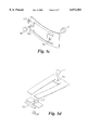
- a further switch for circuit protection is disclosed in which no n-shaped spring plate, or arcuated resilient plate is used as disclosed in the previous patents, but an upper supporting lever 32 and a lower supporting lever 33 are provided at a proper distance above and under the arc changing position, respectively, on the disk-shaped bimetal alloy plate 31 in the switch body functioning as a seesaw, which, together with a lever 34 having a tripping space, cause the disk-shaped bimetal alloy plate 31 functioning to trip in both directions, thus effects the closing and opening of the circuit by pushing or pulling actions.
- the alloy plate used in this patent is a relatively complicated disk-shaped bimetal alloy plate 31. As shown in FIG.
- the disk-shaped bimetal alloy plate 31 is structured with its central face extending from a free end to a fixing end into a contact spring plate 311, the contact spring plate 311 being provided on the extremity with a platinum contacting point 3111 for contact with the platinum contacting point 312. Then, the disk-shaped bi-metal alloy plate 31 is formed into the configuration with a wider free end and a narrower fixing end (W1>W2). As a result, when the fixing end of the disk-shaped metal alloy plate 31 is reduced to a smaller width (W2), the internal stress causes it to deform into an arcuated dish-like shape, and then, in combination with the upper and lower supporting levers 32, 33, it is possible to effect tripping for circuit protection power current overload.
- W2 width
- Pat. No. 5,828,284 issued on Oct. 27, 1998 discloses another safety switch for overload protection. It can be seen from FIG. 4 that a resilient member 41 (a spring) engaging a driving member 42 is used in the switch, the driving member 42 being connected to a pressing portion 43 above and to a lead plate 44 below, such that when the lead plate 44 is overheated and becomes deformed, the pressing portion is pushed up, causing the switch to open for circuit protection.
- This switch is also rather complicated in that a resilient member and the like are used.
- the object of the present invention is to provide a small-sized simple switch for circuit protection which is simple in structure, easy to operate and inexpensive to manufacture.
- the switch of the present invention serves to control the closing and opening of a circuit just as a typical switch does.
- the switch trips to break the circuit for safety protection of the circuit, and the switch can be reset to normal operation by only depressing a reset button and the circuit will remain closed such that the switch of the present invention can be widely used in various electrical appliances to ensure safe power use.
- the on-off switch of the present invention comprises a body having a reset button, the body being provided on the lower end with at least two embedded wire connecting pads, a first wire connecting pad being provided with a silver contacting point; a lever with one end pivoted to one end of the reset button to be pushed or pulled in cooperation with the reset button; a second wire connecting pad, the upper portion thereof being secured to an alloy plate, the other end of the alloy plate being pivoted to the lever and having a silver contacting point; during the power overload, the alloy plate originally in contact with the first wire connecting pad expands and becomes deformed, causing the lever to be pushed up, and the silver contacting point on the first wire connecting pad and the silver contacting point on the alloy plate which are in contact with each other to become disengaged, thus breaking the current for circuit protection.
- FIG. 1 is a side view showing the structure of a conventional switch for circuit protection.
- FIG. 2 is a side view showing the structure of another conventional switch for circuit protection.
- FIG. 3a is a side view showing the structure of still another conventional switch for circuit protection.
- FIG. 3b is a side view showing the structure of the alloy plate used in the switch shown in FIG. 3a.
- FIG. 4 is a side view showing the structure of a still further conventional switch for circuit protection.
- FIG. 5a is a side view showing the structure of a small-sized simple switch for circuit protection of the present invention in the "OFF" condition.
- FIG. 5b is a side view showing the structure of a small-sized simple switch for circuit protection of the present invention in the "ON" condition.
- FIG. 5c is a side view showing the structure of the alloy plate used in the small-sized simple switch for circuit protection of the present invention.
- FIG. 5d is a side view showing the structure of the alloy plate of another configuration used in the small-sized simple switch for circuit protection of the present invention.
- FIG. 6 is a side view showing another embodiment of the small-sized simple switch for circuit protection of the present invention.
- FIGS. 5a and 5b are side views showing the structure of a small-sized simple switch for circuit protection of the present invention in the "OFF" and “ON” conditions, respectively.
- the small-sized simple switch for circuit protection comprises a body 50, a reset button 51 being pivotally connected to the upper portion thereof via a pivot 511 and able to swing side to side.
- a lever 53 is pivotally connected to the left end of the 51 such that the lever 53 can be pushed and pulled relative to each other.
- a pair of detent portions 52 disposed on two sides of the body 50 are advantageous for the switch to be fixed into any electrical appliance.
- a pair of wire connecting pad 55, 56 are embedded in the lower face of the body 50 wherein the first wire connecting pad 55 is provided with a silver contacting point 59 and one end of the alloy plate 54 is secured to the second wire connecting pad 56 by means of a rivet 57.
- the alloy plate 54 is a hollow rectangular structure and the portion secured to the second wire connecting pad is projected into the hollow portion (as shown in FIG. 5c), the other end of the alloy plate 54 is provided with a through hole 542 which is combined with a rivet to form a silver contacting point 58. It can be seen from FIG.
- the alloy plate 54 is highly resilient because of its approximately rectangular and hollow structure as shown in FIG. 5c and it is hooked and connected by the lever 53 through a projection 543.
- the alloy plate 54 consists of different alloy materials with different thermal expansion coefficients such that the alloy plate becomes deformed upward due to thermal expansion during the power overload, causing the silver contacting points 58, 59 which are originally in contact with each other to become disengaged, thus causing the switch to be turned “OFF" to achieve the safety protection of the circuit. Then, the alloy plate bends up and deforms due to expansion and pushes the lever 53 such that the reset button 51 changes from the originally left depressed condition to the right depressed condition.
- FIG. 5d shows another configuration of the alloy plate of the present invention wherein the alloy plate is also of a hollow configuration which is different from that shown in FIG. 5c in that the originally disengaged members 54a and 54b are bonded by welding, and the member 54a still has a projection portion 543' for connecting the lever 53, a through hole 542', and a silver contacting point 58' for contacting the silver contacting point 59 on the first wire connecting pad 55.
- the member 54b is also provided with a through hole 541' for fixing to the second wire connecting pad 56 by a rivet 57'.
- an alloy plate which consists of two members bonded together is used instead of the integrally formed alloy plate, which saves material consumption and thus reduces the manufacturing cost.
- FIG. 6 shows another embodiment of the present invention wherein a third wire connecting pad 61 is embedded into the lower portion of the body 50 and is connected to a neon lamp 62 by a lead and to the second wire connecting pad, such that when the switch is turned on, the neon lamp is lighten to indicate that the switch is in the "ON" operating condition.
Landscapes
- Thermally Actuated Switches (AREA)
- Breakers (AREA)
- Interface Circuits In Exchanges (AREA)
- Amplifiers (AREA)
- Burglar Alarm Systems (AREA)
Abstract
A small-sized simple switch for circuit protection of the present invention is simple in structure and easy to operate, and can be readily switched for safety protection of circuits. An alloy plate of the present invention is highly resilient. When in overload, the alloy plate expands and becomes deformed due to the different thermal expansion coefficient and is deformed upward to become disengaged from a wire connecting pad with which it is originally in contact, causing the switch to be switched from the "ON" condition to the "OFF" condition. The alloy plate pushes a lever pivoted to the moving end of the alloy plate to move up such that the lever pushes one end of a pivoted reset button to move up. A user only has to depress the reset button and the switch will be again in the "ON" condition such that repeated ON/OFF conditions of the protection circuit can be effected. If there is no overload on the circuit, the switch of the present invention will be operated to be in "ON" or "OFF" condition as ordinary switches.
Description
1. Field of the Invention
The small-sized simple switch for protecting circuit of the present invention relates to a circuit protection device which is simple in structure and used to control ON/OFF of a circuit and, in particular, to a switch which automatically trips for circuit protection during power overload and which resets the circuit to the original "ON" condition only after the user depresses a reset button on the switch.
2. Description of Related Art
Conventional switches for indoor use or for use on electrical appliances are of the pressing type which effect switching between the closing and opening of a circuit by depressing a switch's ON/OFF button. However, these switches only serve the function of switching between the closing and the opening of a circuit and can not ensure safety for power supply for these switches do not automatically trip or cut off the power supply for circuit protection when a power overload exists.
In U.S. Pat. No. 5,262,748 issued on Nov. 16, 1993 (see FIG. 1), a switch for circuit protection is disclosed in which an n-shaped spring plate 11 springs up when the power is overload and then an alloy plate 13 is moved up by an actuating lever 12, causing contacting points 14, 15 to become disengaged. With this switch, in addition to requiring the n-shaped spring plate 11, another support lever 17 is connected under the center of a pressing portion 16 and a round head 171 of the support lever is embedded in a braking slot 18 so as to control the swing of the support lever 17 back and forth such that both the structure and the operation of the switch are rather complicated. In RON application Pat. No. 82,204,642 published on Jun. 21, 1993 (see FIG. 2), another switch for circuit protection is disclosed in which an arcuated resilient plate 21 is pivoted to a contact spring plate 22 and abuts against an actuating plate 24 when the platinum contacting point 221 of the contact spring plate 22 is in contact with the platinum contacting point 231 of an wire connecting pad 23. The structure of this switch is also complicated. In U.S. Pat. No. 5,760,672 issued on Jun. 2, 1998 (see FIG. 3a), a further switch for circuit protection is disclosed in which no n-shaped spring plate, or arcuated resilient plate is used as disclosed in the previous patents, but an upper supporting lever 32 and a lower supporting lever 33 are provided at a proper distance above and under the arc changing position, respectively, on the disk-shaped bimetal alloy plate 31 in the switch body functioning as a seesaw, which, together with a lever 34 having a tripping space, cause the disk-shaped bimetal alloy plate 31 functioning to trip in both directions, thus effects the closing and opening of the circuit by pushing or pulling actions. Moreover, the alloy plate used in this patent is a relatively complicated disk-shaped bimetal alloy plate 31. As shown in FIG. 3b, the disk-shaped bimetal alloy plate 31 is structured with its central face extending from a free end to a fixing end into a contact spring plate 311, the contact spring plate 311 being provided on the extremity with a platinum contacting point 3111 for contact with the platinum contacting point 312. Then, the disk-shaped bi-metal alloy plate 31 is formed into the configuration with a wider free end and a narrower fixing end (W1>W2). As a result, when the fixing end of the disk-shaped metal alloy plate 31 is reduced to a smaller width (W2), the internal stress causes it to deform into an arcuated dish-like shape, and then, in combination with the upper and lower supporting levers 32, 33, it is possible to effect tripping for circuit protection power current overload. U.S. Pat. No. 5,828,284 issued on Oct. 27, 1998 (see FIG. 4) discloses another safety switch for overload protection. It can be seen from FIG. 4 that a resilient member 41 (a spring) engaging a driving member 42 is used in the switch, the driving member 42 being connected to a pressing portion 43 above and to a lead plate 44 below, such that when the lead plate 44 is overheated and becomes deformed, the pressing portion is pushed up, causing the switch to open for circuit protection. This switch, however, is also rather complicated in that a resilient member and the like are used.
From the foregoing, it can be seen that conventional circuit protection switches are all implemented by using a complicated structure which increases the cost.
The object of the present invention is to provide a small-sized simple switch for circuit protection which is simple in structure, easy to operate and inexpensive to manufacture. During normal operation, the switch of the present invention serves to control the closing and opening of a circuit just as a typical switch does. During the power overload, the switch trips to break the circuit for safety protection of the circuit, and the switch can be reset to normal operation by only depressing a reset button and the circuit will remain closed such that the switch of the present invention can be widely used in various electrical appliances to ensure safe power use. To achieve the above object, the on-off switch of the present invention comprises a body having a reset button, the body being provided on the lower end with at least two embedded wire connecting pads, a first wire connecting pad being provided with a silver contacting point; a lever with one end pivoted to one end of the reset button to be pushed or pulled in cooperation with the reset button; a second wire connecting pad, the upper portion thereof being secured to an alloy plate, the other end of the alloy plate being pivoted to the lever and having a silver contacting point; during the power overload, the alloy plate originally in contact with the first wire connecting pad expands and becomes deformed, causing the lever to be pushed up, and the silver contacting point on the first wire connecting pad and the silver contacting point on the alloy plate which are in contact with each other to become disengaged, thus breaking the current for circuit protection.
FIG. 1 is a side view showing the structure of a conventional switch for circuit protection.
FIG. 2 is a side view showing the structure of another conventional switch for circuit protection.
FIG. 3a is a side view showing the structure of still another conventional switch for circuit protection.
FIG. 3b is a side view showing the structure of the alloy plate used in the switch shown in FIG. 3a.
FIG. 4 is a side view showing the structure of a still further conventional switch for circuit protection.
FIG. 5a is a side view showing the structure of a small-sized simple switch for circuit protection of the present invention in the "OFF" condition.
FIG. 5b is a side view showing the structure of a small-sized simple switch for circuit protection of the present invention in the "ON" condition.
FIG. 5c is a side view showing the structure of the alloy plate used in the small-sized simple switch for circuit protection of the present invention.
FIG. 5d is a side view showing the structure of the alloy plate of another configuration used in the small-sized simple switch for circuit protection of the present invention.
FIG. 6 is a side view showing another embodiment of the small-sized simple switch for circuit protection of the present invention.
Referring to FIGS. 5a and 5b, which are side views showing the structure of a small-sized simple switch for circuit protection of the present invention in the "OFF" and "ON" conditions, respectively. The small-sized simple switch for circuit protection comprises a body 50, a reset button 51 being pivotally connected to the upper portion thereof via a pivot 511 and able to swing side to side. A lever 53 is pivotally connected to the left end of the 51 such that the lever 53 can be pushed and pulled relative to each other. A pair of detent portions 52 disposed on two sides of the body 50 are advantageous for the switch to be fixed into any electrical appliance. A pair of wire connecting pad 55, 56 are embedded in the lower face of the body 50 wherein the first wire connecting pad 55 is provided with a silver contacting point 59 and one end of the alloy plate 54 is secured to the second wire connecting pad 56 by means of a rivet 57. The alloy plate 54 is a hollow rectangular structure and the portion secured to the second wire connecting pad is projected into the hollow portion (as shown in FIG. 5c), the other end of the alloy plate 54 is provided with a through hole 542 which is combined with a rivet to form a silver contacting point 58. It can be seen from FIG. 5a that the switch is in the "OFF" condition wherein the reset button 51 is depressed to the right such that the lever 53 is pulled up, causing the silver contacting points 58, 59 to be out of contact, thus bringing the switch into the "OFF" condition. The alloy plate 54 is highly resilient because of its approximately rectangular and hollow structure as shown in FIG. 5c and it is hooked and connected by the lever 53 through a projection 543. When depressing on the reset button 51 to the left, the switch is turned on, causing the connected circuit to be in the "ON" condition and the switch is in the condition as shown in FIG. 5b wherein the lever 53 pushes the alloy plate 54 down, causing the alloy plate 54 to become bent down and bringing the silver contacting point 58 into contact with the silver contacting point 59 on the first wire connecting pad 55 such that the switch is turned on. The alloy plate 54 consists of different alloy materials with different thermal expansion coefficients such that the alloy plate becomes deformed upward due to thermal expansion during the power overload, causing the silver contacting points 58, 59 which are originally in contact with each other to become disengaged, thus causing the switch to be turned "OFF" to achieve the safety protection of the circuit. Then, the alloy plate bends up and deforms due to expansion and pushes the lever 53 such that the reset button 51 changes from the originally left depressed condition to the right depressed condition. The switch can be reset to the turned on condition again only by the user depressing the reset button 51 to the left once more. FIG. 5d shows another configuration of the alloy plate of the present invention wherein the alloy plate is also of a hollow configuration which is different from that shown in FIG. 5c in that the originally disengaged members 54a and 54b are bonded by welding, and the member 54a still has a projection portion 543' for connecting the lever 53, a through hole 542', and a silver contacting point 58' for contacting the silver contacting point 59 on the first wire connecting pad 55. In addition, the member 54b is also provided with a through hole 541' for fixing to the second wire connecting pad 56 by a rivet 57'. In this configuration, an alloy plate which consists of two members bonded together is used instead of the integrally formed alloy plate, which saves material consumption and thus reduces the manufacturing cost.
FIG. 6 shows another embodiment of the present invention wherein a third wire connecting pad 61 is embedded into the lower portion of the body 50 and is connected to a neon lamp 62 by a lead and to the second wire connecting pad, such that when the switch is turned on, the neon lamp is lighten to indicate that the switch is in the "ON" operating condition.
The foregoing illustrates only what are the preferred configurations of the present invention without limiting the scope thereof. It is intended that all the modifications and changes not departing from the spirit of the present invention are considered as equivalent implementation of the present invention and should be covered in the scope as defined in the appended claims.
Claims (3)
1. A small-sized simple switch for circuit protection comprises a body; a pressing portion being pivotally connected to the upper portion of said body; at least two wire connecting pads being embedded in the lower face of said body, wherein a first wire connecting pad is provided with a silver contacting point; and a lever with an upper end pivoted to one end of the pressing portion to be pushed or pulled in cooperation with the pressing portion; wherein a second wire connecting pad has an upper portion secured to an alloy plate, the other end of the alloy plate being pivoted to the lever and having a silver contacting point; wherein the alloy plate is highly resilient; and that in normal temperature, by depressing the pressing portion, the alloy plate becomes resiliently bent, causing the silver contacting point to be in or out of contact with the first wire connecting pad and the switch is turned on or off through pushing or pulling the lever, and during overload, the alloy plate expands and becomes deformed only due to its own intrinsic resilient forces, causing the lever to be pushed up and the pressing portion to move to its original position, and the silver contacting point on the first wire connecting pad and the silver contacting point on the alloy plate which are in contact with each other to become disengaged, rendering the switch to be in off condition for circuit protection.
2. A small-sized simple switch according to claim 1 further comprising a third wire connecting pad connected to a neon lamp by a lead and to the second wire connecting pad, such that when the switch is turned on, the neon lamp is lighten to indicate that the switch is in the "ON" operating condition.
3. The small-sized simple switch according to claim 1 wherein the body is provided externally with a detent portion for fixing purpose when the switch is assembled.
Applications Claiming Priority (3)
| Application Number | Priority Date | Filing Date | Title |
|---|---|---|---|
| TW88202642 | 1999-02-12 | ||
| TW88202642 | 1999-02-12 | ||
| CA002271444A CA2271444C (en) | 1999-02-12 | 1999-05-10 | Small-sized simple switch for protecting circuit |
Publications (1)
| Publication Number | Publication Date |
|---|---|
| US6072381A true US6072381A (en) | 2000-06-06 |
Family
ID=32094383
Family Applications (1)
| Application Number | Title | Priority Date | Filing Date |
|---|---|---|---|
| US09/304,780 Expired - Lifetime US6072381A (en) | 1999-02-12 | 1999-05-04 | Small-sized simple switch for protecting circuit |
Country Status (3)
| Country | Link |
|---|---|
| US (1) | US6072381A (en) |
| CA (1) | CA2271444C (en) |
| DE (1) | DE29907707U1 (en) |
Cited By (32)
| Publication number | Priority date | Publication date | Assignee | Title |
|---|---|---|---|---|
| US6249209B1 (en) * | 1999-09-17 | 2001-06-19 | Tsung-Mou Yu | Switch structure having a current overloading protection mechanism |
| US6252490B1 (en) * | 1999-10-21 | 2001-06-26 | Wen-Jang Lin | Safety plug and switch device |
| US6252489B1 (en) * | 1999-11-10 | 2001-06-26 | Tsung-Mou Yu | Switch structure |
| US6275134B1 (en) * | 2000-03-01 | 2001-08-14 | Tsan-Chi Chen | Safety switch with a rocker type actuator and trip-off contact |
| US6275133B1 (en) * | 1999-12-03 | 2001-08-14 | Tsung-Mou Yu | Switch structure |
| US6307459B1 (en) * | 2000-01-05 | 2001-10-23 | Tsung-Mou Yu | Power switch device |
| US6307460B1 (en) * | 2000-02-01 | 2001-10-23 | Tsung-Mou Yu | Power switch device |
| US6353380B1 (en) * | 2000-01-27 | 2002-03-05 | Tsung-Mou Yu | Power switch device |
| US6400250B1 (en) * | 2000-07-14 | 2002-06-04 | Tsung-Mou Yu | Safety switch |
| US6445273B1 (en) * | 1999-10-29 | 2002-09-03 | Tsung-Mou Yu | Overload-protection push-button switch with automatic resetting mechanism |
| US6480090B1 (en) * | 2000-11-20 | 2002-11-12 | Tsung-Mou Yu | Universal device for safety switches |
| US6512441B1 (en) * | 1999-06-24 | 2003-01-28 | Tsung-Mou Yu | Push-button switch of overload protection (II) |
| US6577221B1 (en) * | 2001-11-30 | 2003-06-10 | Ming-Shan Wang | Safety switch |
| US6617952B1 (en) * | 2002-02-26 | 2003-09-09 | Tsung-Mou Yu | Switch with adjustable spring |
| US6617951B2 (en) * | 2001-08-24 | 2003-09-09 | Tsung-Mou Yu | Safety switch |
| US6703917B2 (en) * | 2001-10-10 | 2004-03-09 | The United States Of America As Represented By The Secretary Of The Navy | Resettable fuse/circuit interrupter with visual fault indication |
| US20050264391A1 (en) * | 2004-05-26 | 2005-12-01 | Tsung-Mou Yu | Safety switch device |
| US6984798B1 (en) * | 2004-10-19 | 2006-01-10 | Chen Dung Lu | Safety switch |
| US20070001798A1 (en) * | 2005-07-02 | 2007-01-04 | Tsung-Mou Yu | Protection device for switches |
| US20070247272A1 (en) * | 2006-04-20 | 2007-10-25 | Fontaine Lucien P | Thermally activated circuit interrupter |
| US20090121821A1 (en) * | 2007-11-14 | 2009-05-14 | Tsung Mou Yu | Safety switch |
| US20090184795A1 (en) * | 2008-01-22 | 2009-07-23 | Albert Huang | Safety switch |
| US7583175B2 (en) * | 2007-11-16 | 2009-09-01 | Tsung Mou Yu | Safety switch |
| US20090267724A1 (en) * | 2008-04-23 | 2009-10-29 | Sun-Lite Sockets Industry Inc. | Temperature control switch |
| US20100308952A1 (en) * | 2009-06-03 | 2010-12-09 | Tsung Mou Yu | Safety Device For Switch |
| US20110162947A1 (en) * | 2010-01-07 | 2011-07-07 | Albert Huang | Safety switch |
| US20120126930A1 (en) * | 2009-06-05 | 2012-05-24 | Hofsaess Marcel P | Bimetal part and temperature-dependent switch equipped therewith |
| US20140292473A1 (en) * | 2013-03-27 | 2014-10-02 | Eltek S.P.A. | Actuator device with stable working positions |
| US20150364866A1 (en) * | 2014-01-03 | 2015-12-17 | Brainwave Research Corporation | Electrical cord plug eject mechanism |
| US10529513B1 (en) * | 2018-10-02 | 2020-01-07 | Green Idea Tech Inc. | Overheating destructive switch |
| CN111816504A (en) * | 2020-08-04 | 2020-10-23 | 苏州英忆新材料有限公司 | A push-button mobile socket with double anti-overload function |
| US20230335358A1 (en) * | 2020-06-30 | 2023-10-19 | Bourns Kk | Electric circuit |
Families Citing this family (2)
| Publication number | Priority date | Publication date | Assignee | Title |
|---|---|---|---|---|
| US11675809B2 (en) | 2021-03-02 | 2023-06-13 | International Business Machines Corporation | Replicating data changes using multiple storage devices and tracking records of pending data changes stored on the storage devices |
| US11475043B2 (en) | 2021-03-05 | 2022-10-18 | International Business Machines Corporation | Machine learning based application of changes in a target database system |
Citations (11)
| Publication number | Priority date | Publication date | Assignee | Title |
|---|---|---|---|---|
| US2563175A (en) * | 1950-10-03 | 1951-08-07 | Julia Kitman | Thermal circuit breaker |
| US4337450A (en) * | 1980-06-09 | 1982-06-29 | Eaton Corporation | Remote control electro-thermal actuator switch |
| US5262748A (en) * | 1992-01-13 | 1993-11-16 | Tsung Mou Yu | Fuseless breaking switch |
| WO1994017745A1 (en) * | 1993-02-09 | 1994-08-18 | Plus Endoprothetik Ag | Device for stiffening and/or correcting the spine |
| US5498846A (en) * | 1994-11-07 | 1996-03-12 | Chin; Kun-San | Toggle switches |
| US5539371A (en) * | 1995-09-08 | 1996-07-23 | Yu; Tsung-Mou | Fuseless breaking switch |
| US5694106A (en) * | 1996-12-16 | 1997-12-02 | Wang; Ming Shan | Safety switch with overload protection circuit |
| US5760672A (en) * | 1997-05-02 | 1998-06-02 | Wang; Ming-Shan | Safety switch built-in with protecting circuit |
| US5828284A (en) * | 1997-12-04 | 1998-10-27 | Huang; Albert | Circuit overload protective device |
| US5847638A (en) * | 1996-06-11 | 1998-12-08 | Sorenson; Richard W. | Thermal circuit protector and switch |
| US5892426A (en) * | 1998-06-12 | 1999-04-06 | Huang; Tse-Chuan | Safety switch with security structure |
-
1999
- 1999-04-30 DE DE29907707U patent/DE29907707U1/en not_active Expired - Lifetime
- 1999-05-04 US US09/304,780 patent/US6072381A/en not_active Expired - Lifetime
- 1999-05-10 CA CA002271444A patent/CA2271444C/en not_active Expired - Fee Related
Patent Citations (11)
| Publication number | Priority date | Publication date | Assignee | Title |
|---|---|---|---|---|
| US2563175A (en) * | 1950-10-03 | 1951-08-07 | Julia Kitman | Thermal circuit breaker |
| US4337450A (en) * | 1980-06-09 | 1982-06-29 | Eaton Corporation | Remote control electro-thermal actuator switch |
| US5262748A (en) * | 1992-01-13 | 1993-11-16 | Tsung Mou Yu | Fuseless breaking switch |
| WO1994017745A1 (en) * | 1993-02-09 | 1994-08-18 | Plus Endoprothetik Ag | Device for stiffening and/or correcting the spine |
| US5498846A (en) * | 1994-11-07 | 1996-03-12 | Chin; Kun-San | Toggle switches |
| US5539371A (en) * | 1995-09-08 | 1996-07-23 | Yu; Tsung-Mou | Fuseless breaking switch |
| US5847638A (en) * | 1996-06-11 | 1998-12-08 | Sorenson; Richard W. | Thermal circuit protector and switch |
| US5694106A (en) * | 1996-12-16 | 1997-12-02 | Wang; Ming Shan | Safety switch with overload protection circuit |
| US5760672A (en) * | 1997-05-02 | 1998-06-02 | Wang; Ming-Shan | Safety switch built-in with protecting circuit |
| US5828284A (en) * | 1997-12-04 | 1998-10-27 | Huang; Albert | Circuit overload protective device |
| US5892426A (en) * | 1998-06-12 | 1999-04-06 | Huang; Tse-Chuan | Safety switch with security structure |
Cited By (41)
| Publication number | Priority date | Publication date | Assignee | Title |
|---|---|---|---|---|
| US6512441B1 (en) * | 1999-06-24 | 2003-01-28 | Tsung-Mou Yu | Push-button switch of overload protection (II) |
| US6249209B1 (en) * | 1999-09-17 | 2001-06-19 | Tsung-Mou Yu | Switch structure having a current overloading protection mechanism |
| US6252490B1 (en) * | 1999-10-21 | 2001-06-26 | Wen-Jang Lin | Safety plug and switch device |
| US6445273B1 (en) * | 1999-10-29 | 2002-09-03 | Tsung-Mou Yu | Overload-protection push-button switch with automatic resetting mechanism |
| US6252489B1 (en) * | 1999-11-10 | 2001-06-26 | Tsung-Mou Yu | Switch structure |
| US6275133B1 (en) * | 1999-12-03 | 2001-08-14 | Tsung-Mou Yu | Switch structure |
| US6307459B1 (en) * | 2000-01-05 | 2001-10-23 | Tsung-Mou Yu | Power switch device |
| US6353380B1 (en) * | 2000-01-27 | 2002-03-05 | Tsung-Mou Yu | Power switch device |
| US6307460B1 (en) * | 2000-02-01 | 2001-10-23 | Tsung-Mou Yu | Power switch device |
| US6275134B1 (en) * | 2000-03-01 | 2001-08-14 | Tsan-Chi Chen | Safety switch with a rocker type actuator and trip-off contact |
| US6400250B1 (en) * | 2000-07-14 | 2002-06-04 | Tsung-Mou Yu | Safety switch |
| US6480090B1 (en) * | 2000-11-20 | 2002-11-12 | Tsung-Mou Yu | Universal device for safety switches |
| US6617951B2 (en) * | 2001-08-24 | 2003-09-09 | Tsung-Mou Yu | Safety switch |
| US6703917B2 (en) * | 2001-10-10 | 2004-03-09 | The United States Of America As Represented By The Secretary Of The Navy | Resettable fuse/circuit interrupter with visual fault indication |
| US6577221B1 (en) * | 2001-11-30 | 2003-06-10 | Ming-Shan Wang | Safety switch |
| US6617952B1 (en) * | 2002-02-26 | 2003-09-09 | Tsung-Mou Yu | Switch with adjustable spring |
| US20050264391A1 (en) * | 2004-05-26 | 2005-12-01 | Tsung-Mou Yu | Safety switch device |
| US7148784B2 (en) * | 2004-05-26 | 2006-12-12 | Tsung-Mou Yu | Safety switch device |
| US6984798B1 (en) * | 2004-10-19 | 2006-01-10 | Chen Dung Lu | Safety switch |
| US20070001798A1 (en) * | 2005-07-02 | 2007-01-04 | Tsung-Mou Yu | Protection device for switches |
| US7292129B2 (en) * | 2005-07-02 | 2007-11-06 | Tsung-Mou Yu | Protection device for switches |
| US20070247272A1 (en) * | 2006-04-20 | 2007-10-25 | Fontaine Lucien P | Thermally activated circuit interrupter |
| US7405645B2 (en) * | 2006-04-20 | 2008-07-29 | Sensata Technologies, Inc. | Thermally activated circuit interrupter |
| US20090121821A1 (en) * | 2007-11-14 | 2009-05-14 | Tsung Mou Yu | Safety switch |
| US7583174B2 (en) * | 2007-11-14 | 2009-09-01 | Tsung Mou Yu | Safety switch |
| US7583175B2 (en) * | 2007-11-16 | 2009-09-01 | Tsung Mou Yu | Safety switch |
| US20090184795A1 (en) * | 2008-01-22 | 2009-07-23 | Albert Huang | Safety switch |
| US7626482B2 (en) * | 2008-01-22 | 2009-12-01 | Albert Huang | Safety switch |
| US20090267724A1 (en) * | 2008-04-23 | 2009-10-29 | Sun-Lite Sockets Industry Inc. | Temperature control switch |
| US7755465B2 (en) * | 2008-04-23 | 2010-07-13 | Sun-Lite Sockets Industry Inc. | Temperature control switch |
| US20100308952A1 (en) * | 2009-06-03 | 2010-12-09 | Tsung Mou Yu | Safety Device For Switch |
| US7982577B2 (en) * | 2009-06-03 | 2011-07-19 | Tsung Mou Yu | Safety device for switch |
| US20120126930A1 (en) * | 2009-06-05 | 2012-05-24 | Hofsaess Marcel P | Bimetal part and temperature-dependent switch equipped therewith |
| US9355801B2 (en) * | 2009-06-05 | 2016-05-31 | Marcel P. HOFSAESS | Bimetal part and temperature-dependent switch equipped therewith |
| US20110162947A1 (en) * | 2010-01-07 | 2011-07-07 | Albert Huang | Safety switch |
| US20140292473A1 (en) * | 2013-03-27 | 2014-10-02 | Eltek S.P.A. | Actuator device with stable working positions |
| US9786455B2 (en) * | 2013-03-27 | 2017-10-10 | Eltek S.P.A. | Actuator device with stable working positions |
| US20150364866A1 (en) * | 2014-01-03 | 2015-12-17 | Brainwave Research Corporation | Electrical cord plug eject mechanism |
| US10529513B1 (en) * | 2018-10-02 | 2020-01-07 | Green Idea Tech Inc. | Overheating destructive switch |
| US20230335358A1 (en) * | 2020-06-30 | 2023-10-19 | Bourns Kk | Electric circuit |
| CN111816504A (en) * | 2020-08-04 | 2020-10-23 | 苏州英忆新材料有限公司 | A push-button mobile socket with double anti-overload function |
Also Published As
| Publication number | Publication date |
|---|---|
| CA2271444A1 (en) | 2000-11-10 |
| DE29907707U1 (en) | 1999-08-05 |
| CA2271444C (en) | 2005-11-22 |
Similar Documents
| Publication | Publication Date | Title |
|---|---|---|
| US6072381A (en) | Small-sized simple switch for protecting circuit | |
| US6590173B2 (en) | Molded case circuit breaker | |
| US6400250B1 (en) | Safety switch | |
| JP3074364U (en) | Overload prevention pushbutton switch | |
| EP1059654A3 (en) | Thermal circuit breaker switch | |
| US6456185B1 (en) | Push-button switch with overload protection | |
| JP2005005139A (en) | Switch | |
| US6552644B2 (en) | Safety press-button switch | |
| TWM382568U (en) | Bipolar type auto power off safety switch | |
| US20020130028A1 (en) | Switch with an override interruption structure | |
| US5982269A (en) | Electric switch and thermal protector | |
| US6275133B1 (en) | Switch structure | |
| US6307459B1 (en) | Power switch device | |
| US6469610B1 (en) | Switch assembly | |
| EP1059653A3 (en) | Thermal circuit breaker switch | |
| JP3074365U (en) | Push button switch with overload protection function and automatic reset function | |
| KR200364982Y1 (en) | Small-sized simple switch for protecting circuit | |
| US6323450B1 (en) | Switch assembly | |
| JP3567116B2 (en) | Oscillator switch structure | |
| JP3063680U (en) | Small and simple switch for circuit protection | |
| US6480090B1 (en) | Universal device for safety switches | |
| TW543058B (en) | Accessory-switch device for circuit breaker | |
| JP2002313209A (en) | Press switch | |
| US5950811A (en) | Electrical switch with user selectable manual/automatic reset | |
| JP3634705B2 (en) | Swing type switch structure |
Legal Events
| Date | Code | Title | Description |
|---|---|---|---|
| STCF | Information on status: patent grant |
Free format text: PATENTED CASE |
|
| FPAY | Fee payment |
Year of fee payment: 4 |
|
| FPAY | Fee payment |
Year of fee payment: 8 |
|
| FPAY | Fee payment |
Year of fee payment: 12 |