US6067861A - Method and apparatus for ultrasonic doppler velocimetry using speed of sound and reflection mode pulsed wideband doppler - Google Patents
Method and apparatus for ultrasonic doppler velocimetry using speed of sound and reflection mode pulsed wideband doppler Download PDFInfo
- Publication number
- US6067861A US6067861A US09/100,293 US10029398A US6067861A US 6067861 A US6067861 A US 6067861A US 10029398 A US10029398 A US 10029398A US 6067861 A US6067861 A US 6067861A
- Authority
- US
- United States
- Prior art keywords
- ultrasonic
- velocity
- sound
- doppler
- speed
- Prior art date
- Legal status (The legal status is an assumption and is not a legal conclusion. Google has not performed a legal analysis and makes no representation as to the accuracy of the status listed.)
- Expired - Fee Related
Links
- 238000000034 method Methods 0.000 title claims abstract description 28
- 238000000827 velocimetry Methods 0.000 title abstract description 3
- 239000012530 fluid Substances 0.000 claims abstract description 68
- 238000013480 data collection Methods 0.000 claims description 6
- 238000005259 measurement Methods 0.000 abstract description 70
- 230000005540 biological transmission Effects 0.000 abstract description 10
- 239000002245 particle Substances 0.000 description 15
- 239000002002 slurry Substances 0.000 description 11
- DNIAPMSPPWPWGF-UHFFFAOYSA-N Propylene glycol Chemical compound CC(O)CO DNIAPMSPPWPWGF-UHFFFAOYSA-N 0.000 description 9
- 230000008569 process Effects 0.000 description 8
- 239000000523 sample Substances 0.000 description 6
- 239000007787 solid Substances 0.000 description 6
- 230000008859 change Effects 0.000 description 5
- 230000000694 effects Effects 0.000 description 5
- 238000000518 rheometry Methods 0.000 description 5
- 229920002125 Sokalan® Polymers 0.000 description 4
- 238000013459 approach Methods 0.000 description 4
- 238000002474 experimental method Methods 0.000 description 4
- 239000007788 liquid Substances 0.000 description 4
- 238000003325 tomography Methods 0.000 description 4
- 238000003384 imaging method Methods 0.000 description 3
- 238000013507 mapping Methods 0.000 description 3
- 239000000725 suspension Substances 0.000 description 3
- 238000012512 characterization method Methods 0.000 description 2
- 230000007423 decrease Effects 0.000 description 2
- 230000001419 dependent effect Effects 0.000 description 2
- 238000010586 diagram Methods 0.000 description 2
- 239000006185 dispersion Substances 0.000 description 2
- 238000005516 engineering process Methods 0.000 description 2
- 239000000463 material Substances 0.000 description 2
- 229910052751 metal Inorganic materials 0.000 description 2
- 239000002184 metal Substances 0.000 description 2
- 239000000203 mixture Substances 0.000 description 2
- 238000012986 modification Methods 0.000 description 2
- 230000004048 modification Effects 0.000 description 2
- 230000003287 optical effect Effects 0.000 description 2
- 238000012552 review Methods 0.000 description 2
- 238000005070 sampling Methods 0.000 description 2
- 238000005204 segregation Methods 0.000 description 2
- 238000012935 Averaging Methods 0.000 description 1
- 238000007476 Maximum Likelihood Methods 0.000 description 1
- BQCADISMDOOEFD-UHFFFAOYSA-N Silver Chemical compound [Ag] BQCADISMDOOEFD-UHFFFAOYSA-N 0.000 description 1
- 230000003321 amplification Effects 0.000 description 1
- 230000002547 anomalous effect Effects 0.000 description 1
- 238000000237 capillary viscometry Methods 0.000 description 1
- 238000006243 chemical reaction Methods 0.000 description 1
- 230000001427 coherent effect Effects 0.000 description 1
- 238000013461 design Methods 0.000 description 1
- 238000006073 displacement reaction Methods 0.000 description 1
- 238000002592 echocardiography Methods 0.000 description 1
- 239000011521 glass Substances 0.000 description 1
- 238000001093 holography Methods 0.000 description 1
- 229910052500 inorganic mineral Inorganic materials 0.000 description 1
- 238000009434 installation Methods 0.000 description 1
- 230000003993 interaction Effects 0.000 description 1
- 229910001338 liquidmetal Inorganic materials 0.000 description 1
- 238000004519 manufacturing process Methods 0.000 description 1
- 238000013508 migration Methods 0.000 description 1
- 230000005012 migration Effects 0.000 description 1
- 239000011707 mineral Substances 0.000 description 1
- 238000012544 monitoring process Methods 0.000 description 1
- 238000003199 nucleic acid amplification method Methods 0.000 description 1
- 230000008520 organization Effects 0.000 description 1
- 230000035515 penetration Effects 0.000 description 1
- 229920003023 plastic Polymers 0.000 description 1
- 239000004033 plastic Substances 0.000 description 1
- 239000000843 powder Substances 0.000 description 1
- 238000012545 processing Methods 0.000 description 1
- 238000005086 pumping Methods 0.000 description 1
- 239000000700 radioactive tracer Substances 0.000 description 1
- 229910052709 silver Inorganic materials 0.000 description 1
- 239000004332 silver Substances 0.000 description 1
- 238000001228 spectrum Methods 0.000 description 1
- 239000000126 substance Substances 0.000 description 1
- 238000002604 ultrasonography Methods 0.000 description 1
- XLYOFNOQVPJJNP-UHFFFAOYSA-N water Substances O XLYOFNOQVPJJNP-UHFFFAOYSA-N 0.000 description 1
Images


Classifications
-
- G—PHYSICS
- G01—MEASURING; TESTING
- G01F—MEASURING VOLUME, VOLUME FLOW, MASS FLOW OR LIQUID LEVEL; METERING BY VOLUME
- G01F1/00—Measuring the volume flow or mass flow of fluid or fluent solid material wherein the fluid passes through a meter in a continuous flow
- G01F1/66—Measuring the volume flow or mass flow of fluid or fluent solid material wherein the fluid passes through a meter in a continuous flow by measuring frequency, phase shift or propagation time of electromagnetic or other waves, e.g. using ultrasonic flowmeters
- G01F1/663—Measuring the volume flow or mass flow of fluid or fluent solid material wherein the fluid passes through a meter in a continuous flow by measuring frequency, phase shift or propagation time of electromagnetic or other waves, e.g. using ultrasonic flowmeters by measuring Doppler frequency shift
-
- G—PHYSICS
- G01—MEASURING; TESTING
- G01F—MEASURING VOLUME, VOLUME FLOW, MASS FLOW OR LIQUID LEVEL; METERING BY VOLUME
- G01F1/00—Measuring the volume flow or mass flow of fluid or fluent solid material wherein the fluid passes through a meter in a continuous flow
- G01F1/66—Measuring the volume flow or mass flow of fluid or fluent solid material wherein the fluid passes through a meter in a continuous flow by measuring frequency, phase shift or propagation time of electromagnetic or other waves, e.g. using ultrasonic flowmeters
- G01F1/666—Measuring the volume flow or mass flow of fluid or fluent solid material wherein the fluid passes through a meter in a continuous flow by measuring frequency, phase shift or propagation time of electromagnetic or other waves, e.g. using ultrasonic flowmeters by detecting noise and sounds generated by the flowing fluid
-
- G—PHYSICS
- G01—MEASURING; TESTING
- G01F—MEASURING VOLUME, VOLUME FLOW, MASS FLOW OR LIQUID LEVEL; METERING BY VOLUME
- G01F1/00—Measuring the volume flow or mass flow of fluid or fluent solid material wherein the fluid passes through a meter in a continuous flow
- G01F1/66—Measuring the volume flow or mass flow of fluid or fluent solid material wherein the fluid passes through a meter in a continuous flow by measuring frequency, phase shift or propagation time of electromagnetic or other waves, e.g. using ultrasonic flowmeters
- G01F1/667—Arrangements of transducers for ultrasonic flowmeters; Circuits for operating ultrasonic flowmeters
- G01F1/668—Compensating or correcting for variations in velocity of sound
-
- G—PHYSICS
- G01—MEASURING; TESTING
- G01N—INVESTIGATING OR ANALYSING MATERIALS BY DETERMINING THEIR CHEMICAL OR PHYSICAL PROPERTIES
- G01N2291/00—Indexing codes associated with group G01N29/00
- G01N2291/02—Indexing codes associated with the analysed material
- G01N2291/028—Material parameters
- G01N2291/02836—Flow rate, liquid level
Definitions
- the invention is an ultrasonic method and apparatus for measuring a velocity profile of a fluid flow. More specifically, the invention is the use of ultrasonic measurements from scatterers within the fluid to obtain both local speed of sound and local fluid velocity.
- the term "scatterer” refers to any feature within the fluid that exhibits a change in the speed of sound through that feature. Most often a change in density defines the scatterer, for example a particle. A change in density may also be the result of fluid density variation resulting from a temperature gradient, concentration gradient or other gradient.
- Ultrasonic scatterer is a feature that scatters ultrasonic sound or energy and exhibits a change in the speed of ultrasonic sound.
- Rheology describes the relation between the strain or rate of strain field and the stress field.
- viscosity is a single parameter that links the rate of shear and the shear stress in the flow field.
- the viscosity cannot be represented in terms of a single parameter and becomes a function of the flow field.
- the local fluid viscosity not only depends on the local concentration of the solids but also on the local rate of shear and its gradient. Often, the solids being transported in the pipeline migrate away from the solid walls and into the core of the flow. As a result, measurement of rheology of the fluid near the wall will yield erroneous results relative to the total flow cross section.
- Rheological characterization of solid-liquid dispersions is commonly performed using off-line measurement devices. This approach has the disadvantage that once a sample is withdrawn from the process stream its rheological properties will begin to change. Most often, the fluids to be characterized have rheologies that intimately depend on the flow field. This dependence is especially true for colloidal suspensions in which size and fractal dimensions of the clusters or aggregates depend strongly on the environment under which they exist. Many of these fluids exhibit shear-dependent viscosity, in the form of shear thinning or shear-thickening behavior, requiring determination of their viscosity at various shear-rates which correspond to the range of shear rates observed in the flow field. Off-line measurements can hardly reproduce the same conditions which exist in a real flow field such as shear induced migration of solid particles. Further, given that the material in the pipeline may not be homogeneous, it will be difficult to obtain a representative sample for off-line measurements.
- ultrasonic Doppler flowmeters can yield the mean velocity inside of a pipe or in a flow field (Fowlis, W. W., 1973, "Liquid Metal Flow Measurements Using an Ultrasonic Doppler Velocimeter,” Nature Phys. Sci., 242, pp. 12-13).
- This approach relies on the principle that the frequency of a longitudinal acoustic wave, reflected from discontinuities or scatterers moving with the flow stream, is shifted.
- FIG. 1 depicts the most common orientation of the transmitter 100 and receiver 102 probes with respect to a pipe 104 and a fluid 106 flowing therein. The difference between the transmitted and received frequencies (frequency shift) is directly proportional to the discontinuity or scatterer velocity.
- Reflection-mode and transmission-mode ultrasonic tomographic imaging systems have been well developed during the past few decades. A thorough review of these systems is provided by Plaskowski, A., Beck, M. S., Thorn, R., and Dyalowski, T., 1995, "Imaging Industrial Flows," IOP Publishing, Ltd, Bristol.
- the use of transmission-mode ultrasonic tomography for measuring the three dimensional velocity profile in a pipe has been demonstrated by Johnson, S. A., Greenleaf, J. F., Hansen, C. R., Tanaka, W. F., Lent, A., Christensen, D. A., and Woolley, R.
- the object space is viewed from several parallel projections. These projections are essentially a series of time delay measurements in an acoustic system, giving the distances between the object-media interfaces from the receiving transducers.
- each transducer In the reflection-mode (pulse-echo), each transducer is used to transmit a short pulse and then receive the resulting reflected acoustic energy as a function of time.
- acoustic reconstruction algorithms are linear and straightforward. The output of the reconstruction process provides the echo strength versus time delay.
- the strength of the echo is a function of the sector angle aperture, local gradient of concentration of the slurry (gradient of acoustic impedance), and opacity of the mixture along the pathlength of the beam if the mixture is attenuative.
- the time delay axis may be converted to a distance (range) from the knowledge of local acoustic velocity. ##EQU2## where c is the local acoustic velocity or local speed of sound and X is the range. It has been assumed that the local speed of sound is a constant over the entire measurement range, thereby the range is directly proportional to the range time delay. The average speed of sound is found from two opposite transducers placed across the pipe.
- the variance in measurement of the range directly depends on the variance in the local speed of sound or concentration of the medium. If the local concentration of the slurry changes dramatically from one point to the next in the flow field, then the range will have a substantial amount of variance and the resulting measurement will be inaccurate.
- data exists for monodisperse particle slurries which show the dependence of the speed of sound on the slurry concentration Kelvin, H. K., 1995, "Theory of Sound Propagation in Suspensions: A Guide to Particle Size and Concentration Characterization," Powder Technology, 82, pp. 115-121
- the actual dependence of speed of sound on concentration would have to be determined for the particular slurry in question using off-line calibration.
- v is the convection velocity and s is the unit vector along the ray path.
- s is the unit vector along the ray path.
- the scalar and vector effects may be separated out by calculating the sum and difference of measurements of time-of-flight taken from the same path.
- the resolution in the time-of-flight measurement is limited to the points at which different rays cross. As the number of projections (rays from different directions) increase, the resolution in velocity measurement improves.
- the reflection mode or the pulse-echo technique is considered more suitable for the measurement of the convection of fluid velocity.
- speed of sound measurements may be more simply obtained using the transmission mode or the time-of-flight measurements, but at a lower spatial resolution.
- Ultrasonic transmission time-of-flight measurements can be used to determine the integrated line-of-sight acoustic velocity in the fluid. If the fluid contains scatterers (e.g. particles), then a coherent reflection system can be used to measure the Doppler frequency shift caused by the fluid flow. The magnitude of the Doppler shift can be used to determine the fluid velocity. Applying a sequence of range gates to the Doppler measurements allows determination of the fluid velocity profile along the line-of-sight of the ultrasonic transducer. When the acoustic velocity is uniform across the cross-section of the pipe, and is axisymmetric then this range-gated ultrasonic Doppler data can provide accurate measurement of the fluid velocity profile.
- scatterers e.g. particles
- both the fluid velocity profile and the acoustic velocity are non-uniform across the cross-section of the pipe.
- the time-of-flight acoustic transmission measurement will be in error because the fluid velocity profile is not taken into account, and the reflection Doppler measurement will be in error because the acoustic velocity profile is not known.
- This will cause a distortion of the fluid velocity profile measured by the ultrasonic Doppler system, because the Doppler shift is proportional to the acoustic velocity and the range gate mapping assumes a uniform acoustic velocity across the pipe.
- a single line measurement cannot accurately solve the complex pipe flow velocity problem.
- the transmission measurement can only solve for the average acoustic velocity, not the acoustic velocity profile.
- the reflection Doppler measurement requires the acoustic velocity profile in order to determine the actual fluid velocity profile.
- a single line-of-sight measurement system does not provide enough information to simultaneously solve for both the acoustic and the fluid velocity profiles.
- a method and apparatus rely upon tomographic measurement of the speed of sound and fluid velocity in a pipe.
- the invention provides a more accurate profile of velocity within flow fields where the speed of sound varies within the cross-section of the pipe. This profile is obtained by reconstruction of the velocity profile from the local speed of sound measurement simultaneously with the flow velocity.
- the method of the present invention is real-time tomographic ultrasonic Doppler velocimetry utilizing a plurality of ultrasonic transmission and reflection measurements along two orthogonal sets of parallel acoustic lines-of-sight as depicted in FIGS. 2a, 2b, and 2c.
- the fluid velocity profile and the acoustic velocity profile are determined by iteration between the following two steps until convergence is reached. This iteration will improve accuracy but in general is not required for velocities much smaller than speed of sound.
- Reflection-mode pulsed wideband Doppler measurement determines the approximate fluid velocity profile along each line-of-sight assuming that the acoustic velocity is known (initially constant).
- FIG. 1 shows a prior art transducer pair for an ultrasonic flowmeter.
- FIG. 2a shows orthogonal lines of sight through a fluid volume.
- FIG. 2b shows a transducer grid
- FIG. 2c shows an alternative transducer grid.
- FIG. 2d is a side view of a transducer block.
- FIG. 2e is a top view of the transducer block.
- FIG. 3 is a block diagram of the apparatus of the present invention.
- FIG. 4 is a flow chart of a first instruction set.
- FIG. 5 is a flow chart of a second instruction set.
- FIG. 6 is a side view of an experimental pipe loop.
- FIG. 7a is a single transducer block.
- FIG. 7b is a paired transducer block.
- FIG. 8 is an electronic block diagram of the transceiver.
- FIG. 9 is flow data from a single transducer.
- FIG. 10a is flow data using 2 cycles at 5 MHz.
- FIG. 10b is flow data using 5 cycles at 5 MHz.
- FIG. 10c is flow data using 10 cycles at 5 MHz.
- FIG. 10d is flow data using 20 cycles at 5 MHz.
- FIG. 11 is a probability density function for axial fluid velocity.
- FIG. 12 is a fluid velocity profile comparing ultrasonic data with laser data.
- FIG. 13a shows velocity profiles from transducers pairs 1, 7, 8, & 14.
- FIG. 13b shows velocity profiles from transducers pairs 2, 6, 9, & 13.
- FIG. 13c shows velocity profiles from transducers pairs 3, 5, 10, & 12.
- FIG. 13d shows velocity profiles from transducers pairs 4 & 11.
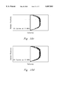
- FIG. 14a is a comparison of transit time between transducer pairs 3, 5, 10, 12, 8, & 1.
- FIG. 14b is a comparison of transit time between transducer pairs 2, 6, 9, 13, 4 & 11.
- the local attenuation can be measured tomographically from the transmitted energy using the transducer grid shown in FIG. 2b or 2c.
- the relation between speed of sound and concentration is more direct and achievable for concentration measurement in a slurry.
- the local speed of sound is measured via time-of-flight measurements.
- the relation between the concentration and speed of sound is established through a one-time off-line calibration for each slurry being transported. This correlation is then used to infer the local concentration in the pipe.
- the method of the present invention for local fluid velocity measurement relies on measurement of the Doppler frequency shift of moving tracer particles, or scatterers, within a pipe flow. Using a short ultrasonic pulse system, the cross-sectional velocity profile is obtained from the Doppler shift at each point in range.
- the Doppler frequency shift is given by ##EQU5## where v is the particle velocity, c is the speed of sound in the fluid, and f is the ultrasonic frequency.
- v is the particle velocity
- c is the speed of sound in the fluid
- f is the ultrasonic frequency.
- the range resolution is approximately equal to one-half of the spatial width of the pulse.
- the range resolution is approximately ##EQU6##
- 5 cycles of 5 MHz (0.3 mm wavelength) yields a range resolution of approximately 0.75 mm.
- Obtaining such high range resolution creates a problem for measurement of the Doppler shift which is on the order of kiloHertz.
- a gated sine-wave of only a few cycles has a relatively wide frequency bandwidth B of approximately, ##EQU7## which is 1 MHz for 5 cycles of a 5 MHz wave.
- the Doppler shift would need to be on the order of or larger than 1 MHz to be distinctly measurable from the frequency spectrum of the echo returned from the particles. Doppler shifts this large would only be expected if the fluid velocity were on the same order as the speed of sound in the fluid. Velocities of interest in pipe flow problems are much lower than the speed of sound. While reducing the bandwidth would allow for good Doppler velocity resolution it would yield a poor range-resolution.
- This conflict is resolved according to the present invention by transmitting and receiving multiple pulses, i.e. observing the fluid over a much longer time interval and obtaining a greater number of observations from each point in the flow field. Multiple pulses, or a plurality of pulses, is at least two pulses, preferably about 5 pulses with no limit of the number of pulses that may be used.
- the grid may be achieved in part with the transducer block shown in FIGS. 2d and 2e.
- the block 200 has a flow passage 202 and pipe connection ports 204a, 204b.
- Transducer ports 206a, 206b are aligned along a common axis 208.
- FIG. 3 includes pairs of ultrasonic transducers 300 (shown schematically) connected to an ultrasonic Doppler computer data collection system 302.
- This system 302 has an ultrasonic transceiver 304 (e.g. Model XIM 1055 Transducer, Xactex Corporation, Pasco, Wash.), computer interface 306, analog-to-digital converter 308, and computer system 310.
- the ultrasonic transceiver 304 generates a specified number of cycles (preferably 5) of ultrasound, then amplifies and transmits them through the ultrasonic transducer 300a.
- the same transducer 300a is used to receive the echoes from the fluid scatterers.
- the received echo signals are passed through a low noise amplifier chain (within the transceiver) with gain adjustable to 99 dB. After amplification the received signals are coherently down converted in frequency from 5 MHz to baseband (centered at DC). Frequency downconversion allows a much smaller amount of data to be recorded by the A/D converter 308 than would direct A/D sampling.
- Computer interface electronics 306 generate the sampling clock pulses used by the A/D converter 308. This number of pulses is adjustable, as is the time delay to the first sample. After A/D conversion the data is stored on the computer systems disk-drive (within the computer system 310). Preferred parameters used in this system are shown in Table 1.
- the first instruction set within the computer receives data from the Reflection-mode Doppler measurement and determines the approximate fluid velocity profile along each line-of-sight assuming that the acoustic velocity is known (initially constant).
- FIG. 4 is a flow chart of this first instruction set.
- the Doppler data is down-converted then read in a time series format by the computer 400.
- An initial range or "fast-time” is selected from which to extract a slow-time waveform 402.
- a Fourier transform is performed along the slow-time 404 from which is obtained the magnitude and the mean velocity at that initial range 406.
- the first instruction set is repeated until all ranges have been assigned a fluid velocity.
- the second instruction set within the computer receives data from transmission measurements of time-of-flight between opposing transducers 500 and determines measurement of the integrated line-of-sight acoustic velocity at a plurality of positions across the pipe cross-section.
- the time-of-flight is calculated along each chord 502 and an average speed of sound is found 504. Utilizing tomographic inversion, the acoustic velocity at each intersection point is determined 506 assuming that the fluid velocity is known (initially assumed known).
- the present invention makes no difference whether the first or second instruction set is done first, nor does it make a difference whether the Doppler or time-of-flight is measured first.
- the results from the first and second instruction sets are combined in Equation 2 but with the local speed of sound as a variable rather than a constant.
- a fully developed flow in a circular pipe was generated using the hydraulic system shown in FIG. 6. Flow was delivered to a 5.5 m long ⁇ 5 cm diameter (nominal) straight PVC pipe section 600.
- the ultrasonic transducer block 602 was located far enough downstream such that the flow became fully developed with no swirl or secondary flow before reaching the transducers.
- the flow rate in the pipe 600 was measured using a positive displacement flowmeter 604.
- the flow rate in the system was laminar such that the Reynolds numbers for all the different conditions were smaller (to much smaller) than 300. For both Carbopol and propylene glycol solutions, sufficient back-scattering was present to produce a velocity profile. However, the signal-to-noise ratio was significantly improved by adding particles.
- particles added were about 45 to 50 micron silver coated glass particles at approximately 0.5 vol%. Settling of particles was finite but not significant for the Newtonian case (u s /U ⁇ 10 -3 ), and almost non-existent for the non-Newtonian fluid which had a strongly shearthinning behavior.
- FIG. 7a shows the transducer block 602 with a single transducer 300a.
- the axial velocity in the pipe was interrogated by this transducer 300a positioned at 45° with respect to the flow direction.
- FIG. 7b shows the orientation of a pair of opposing transducers 300 in the transducer block 602 installed on the pipe.
- the ultrasonic signal was transmitted into the pipe and return signal was received by the transceiver transducer and supplied to the data acquisition system 302 (FIG. 3).
- the processed signal was then converted into a velocity profile.
- For speed of sound measurements the time-of-flight for the signal transmitted by the transceiver to reach the receiver was measured.
- a grid of transducers (5 MHz) was placed around the pipe FIG. 2c. Two transducers 300 were placed along each chord--one for velocity measurement and the other for speed-of-sound measurement.
- the waveform and number of cycles used for triggering the transceiver was generated using an electronic circuitry shown schematically in FIG. 8. Between 5 to 20 cycles were used depending on the particular experimental condition under study.
- LDV Laser Doppler Velocimeter
- Raw data from the pipe flow had a vertical axis of ultrasonic wave signal amplitude distribution representing the range, or fast-time axis which varied from 0 to 50 mm.
- the information along this axis is over-sampled by approximately five times since there are 512 sampled data points for approximately 100 range gates (defined as the path length divided by the range resolution).
- the horizontal axis, time represents the slow-time axis which varies from 0 to 0.2 seconds.
- the frequency of this data along the slow-time direction (horizontal) is proportional to the local velocity and is the Doppler shift of the fluid. Since the Doppler shift is proportional to the fluid velocity, the velocity was obtained by Fourier Transform of the raw data.
- the signal period increases approaching the side-walls of the pipe (near 0 or 50 mm).
- the Fourier transform of the raw data is a velocity profile as shown in FIG. 9 specifically for flow of propylene glycol (Newtonian fluid) in the pipe measured with the UDV of the present invention.
- the distribution is parabolic with a centerline velocity being the same as the measurements made with LDV.
- the distribution of velocity shown on this plot is parabolic, as expected for a laminar Newtonian flow in a circular pipe.
- FIGS. 10a, 10b, 10c, 10d Additional data are shown in FIGS. 10a, 10b, 10c, 10d.
- the speckled appearance of these profiles is due to the random nature of the incoming signal from the scatterers as well as finite domain FFT aliasing. Varying the number of cycles in a pulse transmitted into the fluid affected the velocity density function at each radial location by broadening as the number of cycles decrease from 10 to 2 cycles per pulse. However, increasing the number of cycles to 20 did not improve compared to the 10 cycle pulse conditions. Therefore, most of the experiments were performed with 5 or 10 cycle pulses.
- FIG. 12 shows the comparison between velocity profiles found with UDV and LDV for 0.1% by weight of Carbopol solution. Because of the presence of yield stress in the Carbopol solution, there tends to be a plug or unsheared region in the center of the pipe. This unsheared zone becomes larger and larger as the flow rate decreases and extends throughout the cross-section of the pipe as the flow rate diminishes. Note that the amplitude of velocity and the extent of the plug are measured very closely by both techniques. In most parts, the UDV and LDV measurements show less than 5% discrepancy. This is due to higher variance in UDV measurements at specific points in the pipe, caused by multiple reflection interference.
- the orthogonal grid arrangement shown in FIG. 2c was used for tomographic measurements of the velocity profile and speed of sound.
- the measurements along several of the chords shown should ideally be identical.
- any flow nonuniformity due to lack of symmetry (coming from swirl or secondary flow in the pipe) or settling, saltation, or segregation in the solids within the pipe would be observable by comparison of the results obtained from the different symmetric chords.
- the current measurements for symmetric flow we did not expect to see any difference in the measurements made by symmetric transducers. Nonetheless, such measurement could provide an indication on the measurement uncertainty.
- FIGS. 13a, 13b, 13c, and 13d show the velocity profile at different symmetric chords. Most of the velocity profiles at each chord closely overlap. The close agreement in the results is an indication of the reasonably low level of uncertainty in the measurements, indicating that not only the flow was very symmetric, but also the ultrasonic measurement approach produces repeatable and accurate results.
- FIGS. 14a and 14b are the time-of-flight measurements by various transducer pairs. Each figure includes the signal from two different groups of symmetric transducer pairs (e.g., 4 and 11 are symmetric pairs and likewise 2, 6, 9, & 13).
- Table 2 summarizes the results obtained from these different transducers. Similar to the velocity profile results, these measurements indicate that there is no variation in the speed of sound measured by all the transducer pairs which was expected since the fluid tested is homogeneous. However, nonuniformity in concentration of solids in a slurry flow would be detectable using this approach, provided sufficient concentration differences exist.
Landscapes
- Physics & Mathematics (AREA)
- Electromagnetism (AREA)
- Fluid Mechanics (AREA)
- General Physics & Mathematics (AREA)
- Measuring Volume Flow (AREA)
Abstract
Description
TABLE 1 ______________________________________ The Ultrasonic Doppler System Parameters. Data collection parameters ______________________________________Frequency 5 MHz Number ofcycles 5 Range resolution 0.75 mm Range samples 512 Slow-time samples 1024 Time per waveform 0.5 msec Total data collection time 0.512 sec ______________________________________
              TABLE 2
______________________________________
Speed of Sound Measurements from Various Transducer Pairs.
               Transit Time
                           Xducer Dist.
                                   Speed of
  Xducer Pairs (μs) (mm) Sound(m/s)
______________________________________
4 & 11     55          81.5      1482
  3, 5, 10, & 12 53 78.5 1481
  2, 6, 9, & 13 46 68.6 1491
  1 & 3 32 47.5 1484
______________________________________
Claims (8)
Priority Applications (1)
| Application Number | Priority Date | Filing Date | Title |
|---|---|---|---|
| US09/100,293 US6067861A (en) | 1998-06-18 | 1998-06-18 | Method and apparatus for ultrasonic doppler velocimetry using speed of sound and reflection mode pulsed wideband doppler |
Applications Claiming Priority (1)
| Application Number | Priority Date | Filing Date | Title |
|---|---|---|---|
| US09/100,293 US6067861A (en) | 1998-06-18 | 1998-06-18 | Method and apparatus for ultrasonic doppler velocimetry using speed of sound and reflection mode pulsed wideband doppler |
Publications (1)
| Publication Number | Publication Date |
|---|---|
| US6067861A true US6067861A (en) | 2000-05-30 |
Family
ID=22279054
Family Applications (1)
| Application Number | Title | Priority Date | Filing Date |
|---|---|---|---|
| US09/100,293 Expired - Fee Related US6067861A (en) | 1998-06-18 | 1998-06-18 | Method and apparatus for ultrasonic doppler velocimetry using speed of sound and reflection mode pulsed wideband doppler |
Country Status (1)
| Country | Link |
|---|---|
| US (1) | US6067861A (en) |
Cited By (43)
| Publication number | Priority date | Publication date | Assignee | Title |
|---|---|---|---|---|
| WO2001069231A1 (en) * | 2000-03-14 | 2001-09-20 | Halliburton Energy Services, Inc. | Method of fluid rheology characterization and apparatus therefor |
| US20030018264A1 (en) * | 2001-06-19 | 2003-01-23 | Yoichi Suzuki | Ultrasonic imaging apparatus |
| US6546810B1 (en) * | 1998-07-24 | 2003-04-15 | Institut Francais Du Petrole | Process and device for measuring the velocity of flow of a fluid stream |
| WO2003036241A1 (en) * | 2001-10-26 | 2003-05-01 | The Tokyo Electric Power Company, Incorporated | Doppler ultrasonic flowmeter |
| WO2003097997A1 (en) * | 2002-05-15 | 2003-11-27 | Halliburton Energy Services, Inc. | Acoustic doppler downhole fluid flow measurement |
| WO2004001344A1 (en) * | 2002-06-21 | 2003-12-31 | Bühler AG | Method for determining rheological parameters of a fluid |
| US20040006436A1 (en) * | 2002-07-02 | 2004-01-08 | Morgen Gerald P. | Ultrasonic system and technique for fluid characterization |
| US6837113B1 (en) * | 2003-09-05 | 2005-01-04 | Daniel Industries, Inc. | Enhanced velocity estimation in ultrasonic flow meters |
| US20060016243A1 (en) * | 2004-07-21 | 2006-01-26 | Nevius Timothy A | Acoustic flowmeter calibration method |
| US20060174717A1 (en) * | 2004-09-10 | 2006-08-10 | Kaijo Sonic Corporation | Ultrasonic flow velocity meter and ultrasonic transducer thereof |
| US20060272417A1 (en) * | 2005-06-01 | 2006-12-07 | Daniel Measurement And Control Inc. | Method and ultrasonic meter system for determining pipe roughness |
| US7152490B1 (en) | 2005-08-15 | 2006-12-26 | Daniel Measurement And Control, Inc. | Methods for determining transducer delay time and transducer separation in ultrasonic flow meters |
| EP1500910A4 (en) * | 2002-05-24 | 2007-02-28 | Tokyo Electric Power Co | ULTRASONIC FLOWMETER AND ULTRASONIC FLOW MEASUREMENT METHOD |
| US20070107535A1 (en) * | 2003-12-26 | 2007-05-17 | The Tokyo Electric Power Company Incorported | Ultrasonic flow meter, flow measurement method, and computer program |
| US20070136008A1 (en) * | 2005-12-14 | 2007-06-14 | Thermo Electron Corporation | Method and system for multi-path ultrasonic flow measurement of partially developed flow profiles |
| US20070156355A1 (en) * | 2003-05-06 | 2007-07-05 | Keio University | Ultrasonic flow-velocity distribution meter/flowmeter, method of ultrasonically measuring flow velocity distribution/flowrate, program for ultrasonically measuring flow velocity distribution/flowrate |
| US20070253582A1 (en) * | 2006-04-26 | 2007-11-01 | Thermo Electron Corporation | Transducer assembly |
| WO2008073673A1 (en) | 2006-12-07 | 2008-06-19 | General Electric Company | Ultrasonic flow rate measurement using doppler frequency |
| US20080156107A1 (en) * | 2006-12-29 | 2008-07-03 | Xiaolei Shirley Ao | Ultrasonic flow meter system |
| US20090099459A1 (en) * | 2005-05-12 | 2009-04-16 | Sune Svanberg | Device, System And Method For Determining The Effect Of Photodynamic Or Photothermal Tumor Therapy |
| RU2354938C2 (en) * | 2004-11-03 | 2009-05-10 | Эндресс+Хаузер Флоутек Аг | Device for defining and/or control of volume and/or weight flow rate for measured medium |
| EP2072972A1 (en) * | 2007-12-21 | 2009-06-24 | SICK Engineering GmbH | Device for measuring the movement of a fluid in a pipe |
| WO2009087280A1 (en) * | 2008-01-10 | 2009-07-16 | Metering & Technology Sas | Device for measuring the flow rate of a fluid flowing in a pipe |
| US20100049052A1 (en) * | 2006-10-26 | 2010-02-25 | Cardiogal Ltd. | Non-invasive cardiac parameter measurement |
| US20100299088A1 (en) * | 2007-12-05 | 2010-11-25 | Schlomberger Technology Corporation | Ultrasonic clamp-on multiphase flowmeter |
| US20110103189A1 (en) * | 2008-06-25 | 2011-05-05 | Paulson Peter O | Anomaly detector for pipelines |
| US20110126636A1 (en) * | 2008-08-04 | 2011-06-02 | Hydro Vision Gmbh | Method and device for determining a flow rate of a fluid |
| US8019559B1 (en) | 2007-05-30 | 2011-09-13 | Racine Federated, Inc. | Sonic flow meter and method |
| KR101371373B1 (en) * | 2012-11-26 | 2014-03-12 | 한국표준과학연구원 | Method of ultrasonic flow metering |
| US8700344B2 (en) | 2011-04-20 | 2014-04-15 | Neptune Technology Group Inc. | Ultrasonic flow meter |
| US20140216151A1 (en) * | 2011-09-29 | 2014-08-07 | Optasense Holdings Limited | Flow Monitoring |
| US20140260626A1 (en) * | 2013-03-14 | 2014-09-18 | Weston Aerospace Limited | Apparatus and method for detecting obstructions in pipes or channels |
| CN105091970A (en) * | 2015-08-07 | 2015-11-25 | 北京控制工程研究所 | Dynamic compensation method for ultrasonic flow meter |
| WO2016094643A1 (en) * | 2014-12-10 | 2016-06-16 | General Electric Company | System and method for calculating flow velocity |
| EP3450930A1 (en) * | 2017-08-29 | 2019-03-06 | Nederlandse Organisatie voor toegepast- natuurwetenschappelijk onderzoek TNO | Acoustic measurement of a fluid flow |
| US10371800B2 (en) * | 2015-01-20 | 2019-08-06 | Infineon Technologies Ag | Radar device with noise cancellation |
| US10379198B2 (en) * | 2017-04-06 | 2019-08-13 | International Business Machines Corporation | Determining positions of transducers for receiving and/or transmitting wave signals |
| US10451761B2 (en) | 2015-02-27 | 2019-10-22 | Halliburton Energy Services, Inc. | Ultrasound color flow imaging for oil field applications |
| US10612327B2 (en) | 2015-02-27 | 2020-04-07 | Halliburton Energy Services, Inc. | Ultrasound color flow imaging for oil field applications |
| CN111964772A (en) * | 2020-08-21 | 2020-11-20 | 天津大学 | An underwater sound velocity measuring instrument based on acousto-optic effect |
| US11215489B2 (en) * | 2017-03-07 | 2022-01-04 | Abb Schweiz Ag | Apparatus and method for measuring the flow velocity of a fluid in a pipe |
| CN116027307A (en) * | 2022-11-02 | 2023-04-28 | 哈尔滨工程大学 | Acoustic Doppler instantaneous speed measurement quality evaluation method |
| CN120927517A (en) * | 2025-10-15 | 2025-11-11 | 绍兴舒美针织有限公司 | Pigment dispersity monitoring and controlling system for washing-free printed fabric |
Citations (12)
| Publication number | Priority date | Publication date | Assignee | Title |
|---|---|---|---|---|
| US4176337A (en) * | 1977-06-15 | 1979-11-27 | Fried. Krupp Gesellschaft Mit Beschrankter Haftung | Apparatus for measuring the time between received pulses |
| US4993418A (en) * | 1989-01-26 | 1991-02-19 | Minnesota Mining And Manufacturing Company | Doppler blood flow system and method using low frequency noise signal processing |
| US5113867A (en) * | 1990-05-16 | 1992-05-19 | Janszen David A | Fluid flow characterizing |
| US5115670A (en) * | 1990-03-09 | 1992-05-26 | Chevron Research & Technology Company | Measurement of fluid properties of two-phase fluids using an ultrasonic meter |
| US5226328A (en) * | 1989-11-17 | 1993-07-13 | Ads Environmental Services, Inc. | Velocity measurement system |
| US5341809A (en) * | 1990-08-31 | 1994-08-30 | Hitachi, Ltd. | Ultrasonic flowmeter |
| US5363848A (en) * | 1992-11-16 | 1994-11-15 | Triton Technology, Inc. | Variable illumination of a lumen for acoustic blood flow measurement |
| US5463906A (en) * | 1994-01-24 | 1995-11-07 | Triton Technology, Inc. | Interchangeable disposable acoustic for use with an ultrasonic flowmeter, particularly during extracorporeal measurement of blood flow |
| US5473948A (en) * | 1993-10-15 | 1995-12-12 | United Kingdom Atomic Energy Authority | Flow measurement |
| US5521883A (en) * | 1993-08-30 | 1996-05-28 | Remtech | Method of remotely determining the three-dimensional velocity of a fluid such as air or water |
| US5835884A (en) * | 1996-10-04 | 1998-11-10 | Brown; Alvin E. | Method of determining a characteristic of a fluid |
| US5844144A (en) * | 1997-03-04 | 1998-12-01 | Jennings; Gordon H. | Method for estimating flow velocity |
-
1998
- 1998-06-18 US US09/100,293 patent/US6067861A/en not_active Expired - Fee Related
Patent Citations (12)
| Publication number | Priority date | Publication date | Assignee | Title |
|---|---|---|---|---|
| US4176337A (en) * | 1977-06-15 | 1979-11-27 | Fried. Krupp Gesellschaft Mit Beschrankter Haftung | Apparatus for measuring the time between received pulses |
| US4993418A (en) * | 1989-01-26 | 1991-02-19 | Minnesota Mining And Manufacturing Company | Doppler blood flow system and method using low frequency noise signal processing |
| US5226328A (en) * | 1989-11-17 | 1993-07-13 | Ads Environmental Services, Inc. | Velocity measurement system |
| US5115670A (en) * | 1990-03-09 | 1992-05-26 | Chevron Research & Technology Company | Measurement of fluid properties of two-phase fluids using an ultrasonic meter |
| US5113867A (en) * | 1990-05-16 | 1992-05-19 | Janszen David A | Fluid flow characterizing |
| US5341809A (en) * | 1990-08-31 | 1994-08-30 | Hitachi, Ltd. | Ultrasonic flowmeter |
| US5363848A (en) * | 1992-11-16 | 1994-11-15 | Triton Technology, Inc. | Variable illumination of a lumen for acoustic blood flow measurement |
| US5521883A (en) * | 1993-08-30 | 1996-05-28 | Remtech | Method of remotely determining the three-dimensional velocity of a fluid such as air or water |
| US5473948A (en) * | 1993-10-15 | 1995-12-12 | United Kingdom Atomic Energy Authority | Flow measurement |
| US5463906A (en) * | 1994-01-24 | 1995-11-07 | Triton Technology, Inc. | Interchangeable disposable acoustic for use with an ultrasonic flowmeter, particularly during extracorporeal measurement of blood flow |
| US5835884A (en) * | 1996-10-04 | 1998-11-10 | Brown; Alvin E. | Method of determining a characteristic of a fluid |
| US5844144A (en) * | 1997-03-04 | 1998-12-01 | Jennings; Gordon H. | Method for estimating flow velocity |
Cited By (89)
| Publication number | Priority date | Publication date | Assignee | Title |
|---|---|---|---|---|
| US6546810B1 (en) * | 1998-07-24 | 2003-04-15 | Institut Francais Du Petrole | Process and device for measuring the velocity of flow of a fluid stream |
| WO2001069231A1 (en) * | 2000-03-14 | 2001-09-20 | Halliburton Energy Services, Inc. | Method of fluid rheology characterization and apparatus therefor |
| US6378357B1 (en) * | 2000-03-14 | 2002-04-30 | Halliburton Energy Services, Inc. | Method of fluid rheology characterization and apparatus therefor |
| US20030018264A1 (en) * | 2001-06-19 | 2003-01-23 | Yoichi Suzuki | Ultrasonic imaging apparatus |
| WO2003036241A1 (en) * | 2001-10-26 | 2003-05-01 | The Tokyo Electric Power Company, Incorporated | Doppler ultrasonic flowmeter |
| AU2002344016B9 (en) * | 2001-10-26 | 2006-07-20 | Yasushi Takeda | Doppler ultrasonic flowmeter |
| AU2002344016B2 (en) * | 2001-10-26 | 2006-03-23 | Yasushi Takeda | Doppler ultrasonic flowmeter |
| US6931945B2 (en) | 2001-10-26 | 2005-08-23 | The Tokyo Electric Power Company, Incorporated | Doppler ultrasonic flowmeter |
| CN1327198C (en) * | 2001-10-26 | 2007-07-18 | 东京电力株式会社 | Doppler ultrasonic flowmeter |
| US20050011279A1 (en) * | 2001-10-26 | 2005-01-20 | Yasushi Takeda | Doppler ultrasonic flowmeter |
| US6829947B2 (en) | 2002-05-15 | 2004-12-14 | Halliburton Energy Services, Inc. | Acoustic Doppler downhole fluid flow measurement |
| US20050034530A1 (en) * | 2002-05-15 | 2005-02-17 | Halliburton Energy Services, Inc. | Acoustic doppler downhole fluid flow measurement |
| US20040003658A1 (en) * | 2002-05-15 | 2004-01-08 | Halliburton Energy Services, Inc. | Acoustic doppler downhole fluid flow measurement |
| US6938458B2 (en) | 2002-05-15 | 2005-09-06 | Halliburton Energy Services, Inc. | Acoustic doppler downhole fluid flow measurement |
| WO2003097997A1 (en) * | 2002-05-15 | 2003-11-27 | Halliburton Energy Services, Inc. | Acoustic doppler downhole fluid flow measurement |
| US7289914B2 (en) | 2002-05-24 | 2007-10-30 | Keio University | Ultrasonic flowmeter and ultrasonic flowmetering method |
| EP1500910A4 (en) * | 2002-05-24 | 2007-02-28 | Tokyo Electric Power Co | ULTRASONIC FLOWMETER AND ULTRASONIC FLOW MEASUREMENT METHOD |
| CN100334433C (en) * | 2002-06-21 | 2007-08-29 | 布勒公司 | Method for determining rheological parameters of a fluid |
| DE10227918A1 (en) * | 2002-06-21 | 2004-01-15 | Bühler AG | Method for determining rheological parameters of a fluid |
| US7228728B2 (en) | 2002-06-21 | 2007-06-12 | Buehler Ag | Method for determining rheological parameters of a fluid |
| US20050126268A1 (en) * | 2002-06-21 | 2005-06-16 | Boris Ouriev | Method for determining rheological parameters of a fluid |
| WO2004001344A1 (en) * | 2002-06-21 | 2003-12-31 | Bühler AG | Method for determining rheological parameters of a fluid |
| US20040006436A1 (en) * | 2002-07-02 | 2004-01-08 | Morgen Gerald P. | Ultrasonic system and technique for fluid characterization |
| US6871148B2 (en) * | 2002-07-02 | 2005-03-22 | Battelle Memorial Institute | Ultrasonic system and technique for fluid characterization |
| US7409300B2 (en) | 2003-05-06 | 2008-08-05 | Keio University | Ultrasonic flow-velocity distribution meter/flowmeter, method of ultrasonically measuring flow velocity distribution/flowrate, program for ultrasonically measuring flow velocity distribution/flowrate |
| US20070156355A1 (en) * | 2003-05-06 | 2007-07-05 | Keio University | Ultrasonic flow-velocity distribution meter/flowmeter, method of ultrasonically measuring flow velocity distribution/flowrate, program for ultrasonically measuring flow velocity distribution/flowrate |
| EP1630529A4 (en) * | 2003-05-06 | 2007-09-12 | Univ Keio | ULTRASONIC MEASUREMENT / FLOW METER MEASURING FLOW SPEED DISTRIBUTION, ULTRASONIC MEASUREMENT METHOD FOR FLOW SPEED DISTRIBUTION, PROGRAM FOR ULTRASONIC MEASUREMENT OF FLOW RATE / FLOW RATE DISTRIBUTION |
| WO2005026666A1 (en) * | 2003-09-05 | 2005-03-24 | Daniel Industries, Inc. | Enhanced velocity estimation in ultrasonic flow meters |
| US6837113B1 (en) * | 2003-09-05 | 2005-01-04 | Daniel Industries, Inc. | Enhanced velocity estimation in ultrasonic flow meters |
| US20070107535A1 (en) * | 2003-12-26 | 2007-05-17 | The Tokyo Electric Power Company Incorported | Ultrasonic flow meter, flow measurement method, and computer program |
| US7124621B2 (en) * | 2004-07-21 | 2006-10-24 | Horiba Instruments, Inc. | Acoustic flowmeter calibration method |
| US20060016243A1 (en) * | 2004-07-21 | 2006-01-26 | Nevius Timothy A | Acoustic flowmeter calibration method |
| US20060174717A1 (en) * | 2004-09-10 | 2006-08-10 | Kaijo Sonic Corporation | Ultrasonic flow velocity meter and ultrasonic transducer thereof |
| US7318355B2 (en) * | 2004-09-10 | 2008-01-15 | Kaijo Sonic Corporation | Ultrasonic flow velocity meter and ultrasonic transducer thereof |
| RU2354938C2 (en) * | 2004-11-03 | 2009-05-10 | Эндресс+Хаузер Флоутек Аг | Device for defining and/or control of volume and/or weight flow rate for measured medium |
| US20090099459A1 (en) * | 2005-05-12 | 2009-04-16 | Sune Svanberg | Device, System And Method For Determining The Effect Of Photodynamic Or Photothermal Tumor Therapy |
| WO2006130337A3 (en) * | 2005-06-01 | 2007-07-05 | Daniel Measurement & Control | Method and ultrasonic meter system for determining pipe roughness |
| US7373808B2 (en) * | 2005-06-01 | 2008-05-20 | Daniel Measurement And Control, Inc. | Method and ultrasonic meter system for determining pipe roughness |
| RU2446393C2 (en) * | 2005-06-01 | 2012-03-27 | Дэниел Мэжэмэнт энд Кэнтроул, Инк. | Method of diagnosing pipe roughness and ultrasonic flowmeter |
| US20060272417A1 (en) * | 2005-06-01 | 2006-12-07 | Daniel Measurement And Control Inc. | Method and ultrasonic meter system for determining pipe roughness |
| US7152490B1 (en) | 2005-08-15 | 2006-12-26 | Daniel Measurement And Control, Inc. | Methods for determining transducer delay time and transducer separation in ultrasonic flow meters |
| US7299140B2 (en) | 2005-12-14 | 2007-11-20 | Thermo Fisher Scientific Inc. | Method and system for multi-path ultrasonic flow measurement of partially developed flow profiles |
| RU2392588C2 (en) * | 2005-12-14 | 2010-06-20 | Термо Фишер Сайентифик Инк. | Method and system for multipath ultrasonic measurement of flow parametres and partly developed flow profiles |
| US20070136008A1 (en) * | 2005-12-14 | 2007-06-14 | Thermo Electron Corporation | Method and system for multi-path ultrasonic flow measurement of partially developed flow profiles |
| US20070253582A1 (en) * | 2006-04-26 | 2007-11-01 | Thermo Electron Corporation | Transducer assembly |
| US7795783B2 (en) | 2006-04-26 | 2010-09-14 | Thermo Fisher Scientific Inc. | Transducer assembly |
| RU2368887C2 (en) * | 2006-04-26 | 2009-09-27 | Термо Фишер Сайентифик Инк. | Unit of detector |
| US20100049052A1 (en) * | 2006-10-26 | 2010-02-25 | Cardiogal Ltd. | Non-invasive cardiac parameter measurement |
| US7523676B2 (en) | 2006-12-07 | 2009-04-28 | General Electric Company | Ultrasonic flow rate measurement method and system |
| WO2008073673A1 (en) | 2006-12-07 | 2008-06-19 | General Electric Company | Ultrasonic flow rate measurement using doppler frequency |
| US7581453B2 (en) | 2006-12-29 | 2009-09-01 | General Electric Company | Ultrasonic flow meter system |
| WO2008082807A1 (en) * | 2006-12-29 | 2008-07-10 | General Electric Company | Ultrasonic flow meter using simultaneous time-of-flight and doppler methods |
| US20080156107A1 (en) * | 2006-12-29 | 2008-07-03 | Xiaolei Shirley Ao | Ultrasonic flow meter system |
| US8019559B1 (en) | 2007-05-30 | 2011-09-13 | Racine Federated, Inc. | Sonic flow meter and method |
| US8694270B2 (en) * | 2007-12-05 | 2014-04-08 | Schlumberger Technology Corporation | Ultrasonic clamp-on multiphase flowmeter |
| US20100299088A1 (en) * | 2007-12-05 | 2010-11-25 | Schlomberger Technology Corporation | Ultrasonic clamp-on multiphase flowmeter |
| EP2072972A1 (en) * | 2007-12-21 | 2009-06-24 | SICK Engineering GmbH | Device for measuring the movement of a fluid in a pipe |
| WO2009087280A1 (en) * | 2008-01-10 | 2009-07-16 | Metering & Technology Sas | Device for measuring the flow rate of a fluid flowing in a pipe |
| US8336394B2 (en) | 2008-01-10 | 2012-12-25 | Metering & Technology Sas | Device for measuring the flow rate of a fluid flowing in a pipe |
| US20100294045A1 (en) * | 2008-01-10 | 2010-11-25 | Metering & Technology Sas | Device for measuring the flow rate of a fluid flowing in a pipe |
| US20110103189A1 (en) * | 2008-06-25 | 2011-05-05 | Paulson Peter O | Anomaly detector for pipelines |
| US20110126636A1 (en) * | 2008-08-04 | 2011-06-02 | Hydro Vision Gmbh | Method and device for determining a flow rate of a fluid |
| US8714029B2 (en) * | 2008-08-04 | 2014-05-06 | Hydro Vision Gmbh | Flow measuring device and method including both a doppler frequency shift measurement method and travel time measurement method |
| US8700344B2 (en) | 2011-04-20 | 2014-04-15 | Neptune Technology Group Inc. | Ultrasonic flow meter |
| US9828849B2 (en) * | 2011-09-29 | 2017-11-28 | Optasense Holdings Limited | Flow monitoring using fibre optic distributed acoustic sensors |
| US20140216151A1 (en) * | 2011-09-29 | 2014-08-07 | Optasense Holdings Limited | Flow Monitoring |
| KR101371373B1 (en) * | 2012-11-26 | 2014-03-12 | 한국표준과학연구원 | Method of ultrasonic flow metering |
| US20140260626A1 (en) * | 2013-03-14 | 2014-09-18 | Weston Aerospace Limited | Apparatus and method for detecting obstructions in pipes or channels |
| NO345245B1 (en) * | 2014-12-10 | 2020-11-16 | Gen Electric | System and method for calculating flow velocity |
| CN105738649A (en) * | 2014-12-10 | 2016-07-06 | 通用电气公司 | System and method for calculating flow velocity |
| WO2016094643A1 (en) * | 2014-12-10 | 2016-06-16 | General Electric Company | System and method for calculating flow velocity |
| CN105738649B (en) * | 2014-12-10 | 2020-02-07 | 通用电气公司 | System and method for calculating flow rate |
| US10371551B2 (en) | 2014-12-10 | 2019-08-06 | General Electric Company | System and method for calculating flow velocity |
| US10371800B2 (en) * | 2015-01-20 | 2019-08-06 | Infineon Technologies Ag | Radar device with noise cancellation |
| US10612327B2 (en) | 2015-02-27 | 2020-04-07 | Halliburton Energy Services, Inc. | Ultrasound color flow imaging for oil field applications |
| US10451761B2 (en) | 2015-02-27 | 2019-10-22 | Halliburton Energy Services, Inc. | Ultrasound color flow imaging for oil field applications |
| CN105091970B (en) * | 2015-08-07 | 2018-06-01 | 北京控制工程研究所 | Ultrasonic flowmeter dynamic compensation method |
| CN105091970A (en) * | 2015-08-07 | 2015-11-25 | 北京控制工程研究所 | Dynamic compensation method for ultrasonic flow meter |
| US11215489B2 (en) * | 2017-03-07 | 2022-01-04 | Abb Schweiz Ag | Apparatus and method for measuring the flow velocity of a fluid in a pipe |
| US10379198B2 (en) * | 2017-04-06 | 2019-08-13 | International Business Machines Corporation | Determining positions of transducers for receiving and/or transmitting wave signals |
| US10386452B2 (en) * | 2017-04-06 | 2019-08-20 | International Business Machines Corporation | Determining positions of transducers for receiving and/or transmitting wave signals |
| WO2019045561A1 (en) | 2017-08-29 | 2019-03-07 | Nederlandse Organisatie Voor Toegepast-Natuurwetenschappelijk Onderzoek Tno | Acoustic measurement of a fluid flow |
| US11175165B2 (en) * | 2017-08-29 | 2021-11-16 | Nederlandse Organisatie Voor Toegepast-Natuurwetenschappelijk Onderzoek Tno | Acoustic measurement of a fluid flow |
| EP3450930A1 (en) * | 2017-08-29 | 2019-03-06 | Nederlandse Organisatie voor toegepast- natuurwetenschappelijk onderzoek TNO | Acoustic measurement of a fluid flow |
| CN111964772A (en) * | 2020-08-21 | 2020-11-20 | 天津大学 | An underwater sound velocity measuring instrument based on acousto-optic effect |
| CN116027307A (en) * | 2022-11-02 | 2023-04-28 | 哈尔滨工程大学 | Acoustic Doppler instantaneous speed measurement quality evaluation method |
| CN116027307B (en) * | 2022-11-02 | 2023-09-01 | 哈尔滨工程大学 | Acoustic Doppler instantaneous speed measurement quality evaluation method |
| CN120927517A (en) * | 2025-10-15 | 2025-11-11 | 绍兴舒美针织有限公司 | Pigment dispersity monitoring and controlling system for washing-free printed fabric |
| CN120927517B (en) * | 2025-10-15 | 2026-02-10 | 绍兴舒美针织有限公司 | A pigment dispersion monitoring and control system for waterless printed fabrics |
Similar Documents
| Publication | Publication Date | Title |
|---|---|---|
| US6067861A (en) | Method and apparatus for ultrasonic doppler velocimetry using speed of sound and reflection mode pulsed wideband doppler | |
| CN108490068B (en) | Ultrasonic plane wave scanning multiphase flow visualization measurement device | |
| US7389187B2 (en) | Apparatus and method using an array of ultrasonic sensors for determining the velocity of a fluid within a pipe | |
| Garbini et al. | Measurement of fluid turbulence based on pulsed ultrasound techniques. Part 2. Experimental investigation | |
| US4787252A (en) | Differential correlation analyzer | |
| Lynnworth et al. | Ultrasonic flowmeters: Half-century progress report, 1955–2005 | |
| EP2739942B1 (en) | Fluid visualisation and characterisation system and method | |
| CN114088151B (en) | External clip-on multi-channel ultrasonic flow detection device and detection method | |
| CN100504311C (en) | Apparatus and method using an array of ultrasonic sensors for determining the velocity of a fluid within a pipe | |
| JPS5824816A (en) | Doppler type ultrasonic flowmeter | |
| Rahiman et al. | Design and development of ultrasonic process tomography | |
| Murakawa et al. | Measurement of steam flow rates using a clamp-on ultrasonic flowmeter with various wetness fractions | |
| Kikura et al. | Effect of measurement volume size on turbulent flow measurement using ultrasonic Doppler method | |
| Muramatsu et al. | Applicability of hybrid ultrasonic flow meter for wide-range flow-rate under distorted velocity profile conditions | |
| CN104568375A (en) | Non-intrusive measuring device and method for slug flow parameter | |
| Jaafar et al. | Velocity and turbulence measurements by ultrasound pulse Doppler velocimetry | |
| Johari et al. | Direct measurement of circulation using ultrasound | |
| Rychagov et al. | Multipath flowrate measurements of symmetric and asymmetric flows | |
| Pfund et al. | Inline ultrasonic rheometry by pulsed Doppler | |
| Shekarriz et al. | Slurry pipe flow measurements using tomographic ultrasonic velocimetry and densitometry | |
| CN106443060B (en) | Two-phase flow velocity measurement method based on continuous wave ultrasonic Doppler spectrum correction | |
| Lynnworth | Ultrasonic flowmeters | |
| Liu et al. | Tomographic pulse wave ultrasonic Doppler method for cross-sectional velocity distribution imaging of dispersed oil-water two-phase flow | |
| Coulthard | The principle of ultrasonic cross-correlation flowmetering | |
| Ameran et al. | Multiphase flow velocity measurement of chemical processes using electrical tomography: A review |
Legal Events
| Date | Code | Title | Description |
|---|---|---|---|
| AS | Assignment |
Owner name: BATTELLE MEMORIAL INSTITUTE K1-53, WASHINGTON Free format text: ASSIGNMENT OF ASSIGNORS INTEREST;ASSIGNORS:SHEKARRIZ, ALIREZA;SHEEN, DAVID M.;REEL/FRAME:009274/0096 Effective date: 19980617 |
|
| FPAY | Fee payment |
Year of fee payment: 4 |
|
| AS | Assignment |
Owner name: ENERGY, U.S. DEPARTMENT OF, DISTRICT OF COLUMBIA Free format text: CONFIRMATORY LICENSE;ASSIGNOR:BATTELLE MEMORIAL INSTITUTE, PACIFIC NORTHWEST NATIONAL LAB;REEL/FRAME:016079/0034 Effective date: 19980824 |
|
| FEPP | Fee payment procedure |
Free format text: PAT HOLDER NO LONGER CLAIMS SMALL ENTITY STATUS, ENTITY STATUS SET TO UNDISCOUNTED (ORIGINAL EVENT CODE: STOL); ENTITY STATUS OF PATENT OWNER: LARGE ENTITY |
|
| FPAY | Fee payment |
Year of fee payment: 8 |
|
| REMI | Maintenance fee reminder mailed | ||
| LAPS | Lapse for failure to pay maintenance fees | ||
| STCH | Information on status: patent discontinuation |
Free format text: PATENT EXPIRED DUE TO NONPAYMENT OF MAINTENANCE FEES UNDER 37 CFR 1.362 |
|
| FP | Lapsed due to failure to pay maintenance fee |
Effective date: 20120530 |