US6045979A - Method of photolithographically metallizing at least the inside of holes arranged in accordance with a pattern in a plate of an electrically insulating material - Google Patents
Method of photolithographically metallizing at least the inside of holes arranged in accordance with a pattern in a plate of an electrically insulating material Download PDFInfo
- Publication number
- US6045979A US6045979A US09/017,093 US1709398A US6045979A US 6045979 A US6045979 A US 6045979A US 1709398 A US1709398 A US 1709398A US 6045979 A US6045979 A US 6045979A
- Authority
- US
- United States
- Prior art keywords
- layer
- plate
- chromium
- lacquer coating
- aluminum
- Prior art date
- Legal status (The legal status is an assumption and is not a legal conclusion. Google has not performed a legal analysis and makes no representation as to the accuracy of the status listed.)
- Expired - Fee Related
Links
- 238000000034 method Methods 0.000 title claims abstract description 29
- 239000012777 electrically insulating material Substances 0.000 title claims description 4
- 239000004922 lacquer Substances 0.000 claims abstract description 80
- 229910052751 metal Inorganic materials 0.000 claims abstract description 72
- 239000002184 metal Substances 0.000 claims abstract description 72
- 229910052782 aluminium Inorganic materials 0.000 claims abstract description 32
- XAGFODPZIPBFFR-UHFFFAOYSA-N aluminium Chemical compound [Al] XAGFODPZIPBFFR-UHFFFAOYSA-N 0.000 claims abstract description 32
- 239000011651 chromium Substances 0.000 claims abstract description 30
- 229910052804 chromium Inorganic materials 0.000 claims abstract description 30
- VYZAMTAEIAYCRO-UHFFFAOYSA-N Chromium Chemical compound [Cr] VYZAMTAEIAYCRO-UHFFFAOYSA-N 0.000 claims abstract description 29
- 239000011521 glass Substances 0.000 claims abstract description 10
- PXHVJJICTQNCMI-UHFFFAOYSA-N Nickel Chemical compound [Ni] PXHVJJICTQNCMI-UHFFFAOYSA-N 0.000 claims abstract description 8
- RTAQQCXQSZGOHL-UHFFFAOYSA-N Titanium Chemical compound [Ti] RTAQQCXQSZGOHL-UHFFFAOYSA-N 0.000 claims abstract description 4
- QCWXUUIWCKQGHC-UHFFFAOYSA-N Zirconium Chemical compound [Zr] QCWXUUIWCKQGHC-UHFFFAOYSA-N 0.000 claims abstract description 4
- 229910052759 nickel Inorganic materials 0.000 claims abstract description 4
- 229910052719 titanium Inorganic materials 0.000 claims abstract description 4
- 239000010936 titanium Substances 0.000 claims abstract description 4
- 229910052726 zirconium Inorganic materials 0.000 claims abstract description 4
- 229910017052 cobalt Inorganic materials 0.000 claims abstract description 3
- 239000010941 cobalt Substances 0.000 claims abstract description 3
- GUTLYIVDDKVIGB-UHFFFAOYSA-N cobalt atom Chemical compound [Co] GUTLYIVDDKVIGB-UHFFFAOYSA-N 0.000 claims abstract description 3
- 239000011248 coating agent Substances 0.000 claims description 56
- 238000000576 coating method Methods 0.000 claims description 56
- 150000002739 metals Chemical class 0.000 claims description 8
- 239000007864 aqueous solution Substances 0.000 claims description 7
- 238000004544 sputter deposition Methods 0.000 claims description 7
- VLTRZXGMWDSKGL-UHFFFAOYSA-N perchloric acid Chemical compound OCl(=O)(=O)=O VLTRZXGMWDSKGL-UHFFFAOYSA-N 0.000 claims description 6
- 238000005530 etching Methods 0.000 claims description 5
- 238000007738 vacuum evaporation Methods 0.000 claims description 5
- 239000000956 alloy Substances 0.000 claims description 3
- 229910045601 alloy Inorganic materials 0.000 claims description 3
- 230000005855 radiation Effects 0.000 claims description 2
- 239000010410 layer Substances 0.000 abstract description 65
- 238000004519 manufacturing process Methods 0.000 abstract description 3
- 239000011241 protective layer Substances 0.000 abstract 2
- 239000000243 solution Substances 0.000 description 12
- RYGMFSIKBFXOCR-UHFFFAOYSA-N Copper Chemical compound [Cu] RYGMFSIKBFXOCR-UHFFFAOYSA-N 0.000 description 11
- 229910052802 copper Inorganic materials 0.000 description 11
- 239000010949 copper Substances 0.000 description 11
- XLYOFNOQVPJJNP-UHFFFAOYSA-N water Substances O XLYOFNOQVPJJNP-UHFFFAOYSA-N 0.000 description 11
- HEMHJVSKTPXQMS-UHFFFAOYSA-M Sodium hydroxide Chemical compound [OH-].[Na+] HEMHJVSKTPXQMS-UHFFFAOYSA-M 0.000 description 6
- 239000000693 micelle Substances 0.000 description 5
- CSCPPACGZOOCGX-UHFFFAOYSA-N Acetone Chemical compound CC(C)=O CSCPPACGZOOCGX-UHFFFAOYSA-N 0.000 description 4
- XEEYBQQBJWHFJM-UHFFFAOYSA-N Iron Chemical compound [Fe] XEEYBQQBJWHFJM-UHFFFAOYSA-N 0.000 description 4
- 230000015572 biosynthetic process Effects 0.000 description 4
- JVTAAEKCZFNVCJ-UHFFFAOYSA-N lactic acid Chemical compound CC(O)C(O)=O JVTAAEKCZFNVCJ-UHFFFAOYSA-N 0.000 description 4
- 239000000178 monomer Substances 0.000 description 4
- 239000000758 substrate Substances 0.000 description 4
- ZWEHNKRNPOVVGH-UHFFFAOYSA-N 2-Butanone Chemical compound CCC(C)=O ZWEHNKRNPOVVGH-UHFFFAOYSA-N 0.000 description 3
- 239000012670 alkaline solution Substances 0.000 description 3
- 229940024548 aluminum oxide Drugs 0.000 description 3
- 239000003795 chemical substances by application Substances 0.000 description 3
- 239000007788 liquid Substances 0.000 description 3
- 239000000463 material Substances 0.000 description 3
- 239000000203 mixture Substances 0.000 description 3
- TWNQGVIAIRXVLR-UHFFFAOYSA-N oxo(oxoalumanyloxy)alumane Chemical compound O=[Al]O[Al]=O TWNQGVIAIRXVLR-UHFFFAOYSA-N 0.000 description 3
- 229920000642 polymer Polymers 0.000 description 3
- 229910052709 silver Inorganic materials 0.000 description 3
- 239000004332 silver Substances 0.000 description 3
- 229910001220 stainless steel Inorganic materials 0.000 description 3
- 239000010935 stainless steel Substances 0.000 description 3
- SOGAXMICEFXMKE-UHFFFAOYSA-N Butylmethacrylate Chemical compound CCCCOC(=O)C(C)=C SOGAXMICEFXMKE-UHFFFAOYSA-N 0.000 description 2
- 125000003277 amino group Chemical group 0.000 description 2
- 229920002678 cellulose Polymers 0.000 description 2
- 239000001913 cellulose Substances 0.000 description 2
- 238000002485 combustion reaction Methods 0.000 description 2
- 238000000151 deposition Methods 0.000 description 2
- 238000001704 evaporation Methods 0.000 description 2
- 230000008020 evaporation Effects 0.000 description 2
- 239000007789 gas Substances 0.000 description 2
- 239000004310 lactic acid Substances 0.000 description 2
- 235000014655 lactic acid Nutrition 0.000 description 2
- 239000002245 particle Substances 0.000 description 2
- BASFCYQUMIYNBI-UHFFFAOYSA-N platinum Chemical compound [Pt] BASFCYQUMIYNBI-UHFFFAOYSA-N 0.000 description 2
- 239000000843 powder Substances 0.000 description 2
- 238000007789 sealing Methods 0.000 description 2
- 229920003002 synthetic resin Polymers 0.000 description 2
- 239000000057 synthetic resin Substances 0.000 description 2
- PIZHFBODNLEQBL-UHFFFAOYSA-N 2,2-diethoxy-1-phenylethanone Chemical compound CCOC(OCC)C(=O)C1=CC=CC=C1 PIZHFBODNLEQBL-UHFFFAOYSA-N 0.000 description 1
- RWSOTUBLDIXVET-UHFFFAOYSA-N Dihydrogen sulfide Chemical group S RWSOTUBLDIXVET-UHFFFAOYSA-N 0.000 description 1
- 239000004593 Epoxy Substances 0.000 description 1
- 229910017344 Fe2 O3 Inorganic materials 0.000 description 1
- UFHFLCQGNIYNRP-UHFFFAOYSA-N Hydrogen Chemical compound [H][H] UFHFLCQGNIYNRP-UHFFFAOYSA-N 0.000 description 1
- VYPSYNLAJGMNEJ-UHFFFAOYSA-N Silicium dioxide Chemical compound O=[Si]=O VYPSYNLAJGMNEJ-UHFFFAOYSA-N 0.000 description 1
- 230000002411 adverse Effects 0.000 description 1
- 239000004411 aluminium Substances 0.000 description 1
- 239000012298 atmosphere Substances 0.000 description 1
- QVGXLLKOCUKJST-UHFFFAOYSA-N atomic oxygen Chemical compound [O] QVGXLLKOCUKJST-UHFFFAOYSA-N 0.000 description 1
- 238000005422 blasting Methods 0.000 description 1
- 150000001732 carboxylic acid derivatives Chemical class 0.000 description 1
- 239000000919 ceramic Substances 0.000 description 1
- 229910010293 ceramic material Inorganic materials 0.000 description 1
- 150000001844 chromium Chemical class 0.000 description 1
- 229920006037 cross link polymer Polymers 0.000 description 1
- 230000007423 decrease Effects 0.000 description 1
- 230000001419 dependent effect Effects 0.000 description 1
- 230000008021 deposition Effects 0.000 description 1
- 238000001035 drying Methods 0.000 description 1
- 230000005684 electric field Effects 0.000 description 1
- 238000005868 electrolysis reaction Methods 0.000 description 1
- 238000001962 electrophoresis Methods 0.000 description 1
- 239000001257 hydrogen Substances 0.000 description 1
- 229910052739 hydrogen Inorganic materials 0.000 description 1
- 125000002887 hydroxy group Chemical group [H]O* 0.000 description 1
- -1 hydroxy ions Chemical class 0.000 description 1
- 238000007654 immersion Methods 0.000 description 1
- 230000003993 interaction Effects 0.000 description 1
- 229910052742 iron Inorganic materials 0.000 description 1
- 238000001465 metallisation Methods 0.000 description 1
- 239000004530 micro-emulsion Substances 0.000 description 1
- 239000012044 organic layer Substances 0.000 description 1
- 229920000620 organic polymer Polymers 0.000 description 1
- 239000001301 oxygen Substances 0.000 description 1
- 229910052760 oxygen Inorganic materials 0.000 description 1
- 238000006552 photochemical reaction Methods 0.000 description 1
- 229910052697 platinum Inorganic materials 0.000 description 1
- 125000001453 quaternary ammonium group Chemical group 0.000 description 1
- 239000002904 solvent Substances 0.000 description 1
- 238000011282 treatment Methods 0.000 description 1
- 238000001771 vacuum deposition Methods 0.000 description 1
Images


Classifications
-
- H—ELECTRICITY
- H01—ELECTRIC ELEMENTS
- H01J—ELECTRIC DISCHARGE TUBES OR DISCHARGE LAMPS
- H01J9/00—Apparatus or processes specially adapted for the manufacture, installation, removal, maintenance of electric discharge tubes, discharge lamps, or parts thereof; Recovery of material from discharge tubes or lamps
- H01J9/02—Manufacture of electrodes or electrode systems
- H01J9/14—Manufacture of electrodes or electrode systems of non-emitting electrodes
- H01J9/148—Manufacture of electrodes or electrode systems of non-emitting electrodes of electron emission flat panels, e.g. gate electrodes, focusing electrodes or anode electrodes
-
- G—PHYSICS
- G03—PHOTOGRAPHY; CINEMATOGRAPHY; ANALOGOUS TECHNIQUES USING WAVES OTHER THAN OPTICAL WAVES; ELECTROGRAPHY; HOLOGRAPHY
- G03F—PHOTOMECHANICAL PRODUCTION OF TEXTURED OR PATTERNED SURFACES, e.g. FOR PRINTING, FOR PROCESSING OF SEMICONDUCTOR DEVICES; MATERIALS THEREFOR; ORIGINALS THEREFOR; APPARATUS SPECIALLY ADAPTED THEREFOR
- G03F7/00—Photomechanical, e.g. photolithographic, production of textured or patterned surfaces, e.g. printing surfaces; Materials therefor, e.g. comprising photoresists; Apparatus specially adapted therefor
- G03F7/0005—Production of optical devices or components in so far as characterised by the lithographic processes or materials used therefor
- G03F7/0007—Filters, e.g. additive colour filters; Components for display devices
-
- G—PHYSICS
- G03—PHOTOGRAPHY; CINEMATOGRAPHY; ANALOGOUS TECHNIQUES USING WAVES OTHER THAN OPTICAL WAVES; ELECTROGRAPHY; HOLOGRAPHY
- G03F—PHOTOMECHANICAL PRODUCTION OF TEXTURED OR PATTERNED SURFACES, e.g. FOR PRINTING, FOR PROCESSING OF SEMICONDUCTOR DEVICES; MATERIALS THEREFOR; ORIGINALS THEREFOR; APPARATUS SPECIALLY ADAPTED THEREFOR
- G03F7/00—Photomechanical, e.g. photolithographic, production of textured or patterned surfaces, e.g. printing surfaces; Materials therefor, e.g. comprising photoresists; Apparatus specially adapted therefor
- G03F7/0015—Production of aperture devices, microporous systems or stamps
-
- G—PHYSICS
- G03—PHOTOGRAPHY; CINEMATOGRAPHY; ANALOGOUS TECHNIQUES USING WAVES OTHER THAN OPTICAL WAVES; ELECTROGRAPHY; HOLOGRAPHY
- G03F—PHOTOMECHANICAL PRODUCTION OF TEXTURED OR PATTERNED SURFACES, e.g. FOR PRINTING, FOR PROCESSING OF SEMICONDUCTOR DEVICES; MATERIALS THEREFOR; ORIGINALS THEREFOR; APPARATUS SPECIALLY ADAPTED THEREFOR
- G03F7/00—Photomechanical, e.g. photolithographic, production of textured or patterned surfaces, e.g. printing surfaces; Materials therefor, e.g. comprising photoresists; Apparatus specially adapted therefor
- G03F7/004—Photosensitive materials
- G03F7/09—Photosensitive materials characterised by structural details, e.g. supports, auxiliary layers
- G03F7/11—Photosensitive materials characterised by structural details, e.g. supports, auxiliary layers having cover layers or intermediate layers, e.g. subbing layers
-
- H—ELECTRICITY
- H01—ELECTRIC ELEMENTS
- H01J—ELECTRIC DISCHARGE TUBES OR DISCHARGE LAMPS
- H01J9/00—Apparatus or processes specially adapted for the manufacture, installation, removal, maintenance of electric discharge tubes, discharge lamps, or parts thereof; Recovery of material from discharge tubes or lamps
- H01J9/02—Manufacture of electrodes or electrode systems
- H01J9/14—Manufacture of electrodes or electrode systems of non-emitting electrodes
- H01J9/142—Manufacture of electrodes or electrode systems of non-emitting electrodes of shadow-masks for colour television tubes
- H01J9/146—Surface treatment, e.g. blackening, coating
-
- H—ELECTRICITY
- H05—ELECTRIC TECHNIQUES NOT OTHERWISE PROVIDED FOR
- H05K—PRINTED CIRCUITS; CASINGS OR CONSTRUCTIONAL DETAILS OF ELECTRIC APPARATUS; MANUFACTURE OF ASSEMBLAGES OF ELECTRICAL COMPONENTS
- H05K1/00—Printed circuits
- H05K1/02—Details
- H05K1/09—Use of materials for the conductive, e.g. metallic pattern
-
- H—ELECTRICITY
- H05—ELECTRIC TECHNIQUES NOT OTHERWISE PROVIDED FOR
- H05K—PRINTED CIRCUITS; CASINGS OR CONSTRUCTIONAL DETAILS OF ELECTRIC APPARATUS; MANUFACTURE OF ASSEMBLAGES OF ELECTRICAL COMPONENTS
- H05K3/00—Apparatus or processes for manufacturing printed circuits
- H05K3/0094—Filling or covering plated through-holes or blind plated vias, e.g. for masking or for mechanical reinforcement
-
- G—PHYSICS
- G03—PHOTOGRAPHY; CINEMATOGRAPHY; ANALOGOUS TECHNIQUES USING WAVES OTHER THAN OPTICAL WAVES; ELECTROGRAPHY; HOLOGRAPHY
- G03F—PHOTOMECHANICAL PRODUCTION OF TEXTURED OR PATTERNED SURFACES, e.g. FOR PRINTING, FOR PROCESSING OF SEMICONDUCTOR DEVICES; MATERIALS THEREFOR; ORIGINALS THEREFOR; APPARATUS SPECIALLY ADAPTED THEREFOR
- G03F7/00—Photomechanical, e.g. photolithographic, production of textured or patterned surfaces, e.g. printing surfaces; Materials therefor, e.g. comprising photoresists; Apparatus specially adapted therefor
- G03F7/16—Coating processes; Apparatus therefor
- G03F7/164—Coating processes; Apparatus therefor using electric, electrostatic or magnetic means; powder coating
-
- H—ELECTRICITY
- H01—ELECTRIC ELEMENTS
- H01J—ELECTRIC DISCHARGE TUBES OR DISCHARGE LAMPS
- H01J2209/00—Apparatus and processes for manufacture of discharge tubes
- H01J2209/01—Generalised techniques
- H01J2209/012—Coating
-
- H—ELECTRICITY
- H01—ELECTRIC ELEMENTS
- H01J—ELECTRIC DISCHARGE TUBES OR DISCHARGE LAMPS
- H01J2329/00—Electron emission display panels, e.g. field emission display panels
-
- H—ELECTRICITY
- H05—ELECTRIC TECHNIQUES NOT OTHERWISE PROVIDED FOR
- H05K—PRINTED CIRCUITS; CASINGS OR CONSTRUCTIONAL DETAILS OF ELECTRIC APPARATUS; MANUFACTURE OF ASSEMBLAGES OF ELECTRICAL COMPONENTS
- H05K1/00—Printed circuits
- H05K1/02—Details
- H05K1/03—Use of materials for the substrate
- H05K1/0306—Inorganic insulating substrates, e.g. ceramic, glass
-
- H—ELECTRICITY
- H05—ELECTRIC TECHNIQUES NOT OTHERWISE PROVIDED FOR
- H05K—PRINTED CIRCUITS; CASINGS OR CONSTRUCTIONAL DETAILS OF ELECTRIC APPARATUS; MANUFACTURE OF ASSEMBLAGES OF ELECTRICAL COMPONENTS
- H05K2201/00—Indexing scheme relating to printed circuits covered by H05K1/00
- H05K2201/09—Shape and layout
- H05K2201/09209—Shape and layout details of conductors
- H05K2201/095—Conductive through-holes or vias
- H05K2201/09581—Applying an insulating coating on the walls of holes
-
- H—ELECTRICITY
- H05—ELECTRIC TECHNIQUES NOT OTHERWISE PROVIDED FOR
- H05K—PRINTED CIRCUITS; CASINGS OR CONSTRUCTIONAL DETAILS OF ELECTRIC APPARATUS; MANUFACTURE OF ASSEMBLAGES OF ELECTRICAL COMPONENTS
- H05K2203/00—Indexing scheme relating to apparatus or processes for manufacturing printed circuits covered by H05K3/00
- H05K2203/13—Moulding and encapsulation; Deposition techniques; Protective layers
- H05K2203/1333—Deposition techniques, e.g. coating
- H05K2203/135—Electrophoretic deposition of insulating material
-
- H—ELECTRICITY
- H05—ELECTRIC TECHNIQUES NOT OTHERWISE PROVIDED FOR
- H05K—PRINTED CIRCUITS; CASINGS OR CONSTRUCTIONAL DETAILS OF ELECTRIC APPARATUS; MANUFACTURE OF ASSEMBLAGES OF ELECTRICAL COMPONENTS
- H05K3/00—Apparatus or processes for manufacturing printed circuits
- H05K3/02—Apparatus or processes for manufacturing printed circuits in which the conductive material is applied to the surface of the insulating support and is thereafter removed from such areas of the surface which are not intended for current conducting or shielding
- H05K3/06—Apparatus or processes for manufacturing printed circuits in which the conductive material is applied to the surface of the insulating support and is thereafter removed from such areas of the surface which are not intended for current conducting or shielding the conductive material being removed chemically or electrolytically, e.g. by photo-etch process
- H05K3/061—Etching masks
- H05K3/064—Photoresists
-
- H—ELECTRICITY
- H05—ELECTRIC TECHNIQUES NOT OTHERWISE PROVIDED FOR
- H05K—PRINTED CIRCUITS; CASINGS OR CONSTRUCTIONAL DETAILS OF ELECTRIC APPARATUS; MANUFACTURE OF ASSEMBLAGES OF ELECTRICAL COMPONENTS
- H05K3/00—Apparatus or processes for manufacturing printed circuits
- H05K3/38—Improvement of the adhesion between the insulating substrate and the metal
- H05K3/388—Improvement of the adhesion between the insulating substrate and the metal by the use of a metallic or inorganic thin film adhesion layer
Definitions
- the invention relates to a method of photolithographically metallizing at least the inside of holes arranged in accordance with a pattern in a plate of an electrically insulating material, while using a negative, photosensitive cataphoretic lacquer coating.
- Such perforated plates for example, of glass, quartz glass, synthetic resin or a ceramic material are used, in particular, in field-emission displays and thin electron displays, the metallized holes serving as electrodes to control the electron currents moving towards the luminescent screen provided with phosphors, and the electron currents in plasma displays.
- the surface of such a plate also comprises narrow metal tracks which are used to drive (address) the electrodes.
- the plates are used as control or selection elements.
- Thin electron displays comprise at least two selection plates.
- Such a thin electron display is described in European Patent Application EP-A-464937, filed by Applicants.
- the display described therein comprises, inter alia, a preselection plate and a fine selection plate.
- These plates are, for example, made of glass and have a thickness of 0.5 mm.
- Such a plate comprises a very accurate pattern of holes, for example 400,000 holes each having a diameter of 400 ⁇ m.
- metal selection electrodes which can be individually activated by means of narrow metal tracks on the glass plate material. In said Patent Application no information is given as to which metal is used as the electrode nor how the metal is provided in and around the holes.
- EP-A-539714 there is disclosed an electrophoretic method of manufacturing copper patterns on printed circuit boards by using a negative, photosensitive cataphoretic lacquer.
- a substrate for example, of epoxy to which a copper layer is uniformly applied is immersed in a solution of such a lacquer, the substrate and an inert electrode, for example, of stainless steel being connected to an external current source.
- the copper layer on the substrate serves as the cathode and the inert electrode as the anode, i.e. the copper layer is electrically connected to the negative pole of the current source.
- the solution of the lacquer comprises, inter alia, a mixture of a polymer comprising positively charged groups, unsaturated monomers and a photoinitiator.
- Examples of positively charged groups are the amino group, quaternary ammonium group, sulphonium group and sulphoxonium group.
- the electric field in the solution causes the positively charged mixture to be attracted towards the negatively charged copper layer where it is discharged. This results in the formation of a dense and uniform lacquer coating on the copper layer.
- Such a cataphoretic lacquer must be used to provide three-dimensional structures, such as internally metallized holes.
- the photosensitive lacquer is of the negative type, i.e. exposed parts of the lacquer coating become less soluble in a developing liquid than unexposed parts as a result of a photochemical reaction. Exposure often takes place through a photomask. This difference in solubility enables the lacquer coating to be selectively removed.
- the lacquer pattern formed serves as a mask for an etching agent, so that the copper layer is structured to form a desired pattern which corresponds to the photomask used.
- a disadvantage of this state-of-the-art method is that copper cannot be used as a metal track or electrode in thin electron displays because of undesirable interactions with the electroluminescent phosphors used.
- the metal tracks of the selection plates for example, have a width of only 80 ⁇ m and a thickness of 5 ⁇ m. Under operating conditions, metal tracks having such a small cross-section lead to an enormous ohmic drop, over, a distance of 40 cm if an electrically ill-conducting metal is used.
- electrically well-conducting metals are copper and silver. Copper is unsuitable because of the above-mentioned disadvantage; silver is unattractive because it is expensive. It should be borne in mind that in order to obtain the desired pattern, the major part of the metal layer is removed by means of an etchant.
- aluminum exhibits a good electrical conductivity and a high vapour-deposition or sputtering rate, it can be used as the metal for, in particular, the metal tracks and the electrodes. It has however been found that aluminum is attacked in the known solutions of cataphoretic lacquers. If aluminum is brought into contact with a solution of a cataphoretic lacquer, gas bubbles form at the surface of the aluminum and the aluminum is dissolved in the lacquer solution. As a result, the cataphoretic lacquer coating is deposited in such a large thickness that the light used in the photolithographic step is absorbed to a substantial degree. Exposure of the lacquer coating throughout its thickness and complete curing then becomes problematic, resulting in a poor-quality photolithographic process. In addition, when the lacquer coating is provided, the gas bubbles partially dissolve in the lacquer coating, thereby forming undesirable pinholes in the lacquer coating.
- the metal coating must adhere well to the plate, in particular a glass plate, and be sufficiently electroconductive for use in the narrow metal tracks on the plate, which connect the selection electrodes to the connecting contacts along the periphery of the plate.
- the aluminum layer with a metal layer, the metal being selected from the group consisting of chromium, cobalt, nickel, zirconium and titanium, or from an alloy of two or more of these metals,
- the plate is preferably made of glass, but may alternatively be made of a ceramic or synthetic resin material.
- the thickness of the glass plate is, for example, 0.5 mm.
- the holes can be made in the plate by exposing the plate via a mask to a stream of abrasive powder particles, for example, of aluminum oxide. This method is described in European Patent Application EP-A-562670, filed by Applicants.
- the openings of the holes are, for example, circular in shape.
- the diameter of the holes ranges from 50 ⁇ m to 5 mm.
- the holes formed are slightly conical, which is advantageous for the subsequent metallization of the holes.
- At least one side of the plate is provided with a chromium layer.
- a chromium layer has a thickness, for example, of 10 nm and serves as a bonding layer for the aluminum layer to be subsequently provided.
- An aluminum layer having a thickness, for example, of 5 ⁇ m is provided on the chromium layer. Because of its high evaporation or sputtering rate, aluminum can advantageously be provided by vacuum evaporation or sputtering. Aluminium is chosen because it has a high electrical conductivity and it does not have the above-mentioned disadvantages of copper and silver.
- the chromium layer is preferably also provided by vacuum evaporation or sputtering. Both metals can be provided one after the other by means of the same vacuum deposition system. In the vacuum evaporation or sputtering process, the surface of the plate having the largest diameter of the conical holes faces the evaporation source or sputter target. This results in this surface of the plate and the walls of the holes being coated, in succession, with a chromium layer and an aluminum layer. For certain applications, both sides of the plate are metallized.
- the aluminum layer is subsequently provided with a layer of a metal selected from the group consisting of chromium, nickel, zirconium and titanium, or alloys of two or more of said metals.
- a metal selected from the group consisting of chromium, nickel, zirconium and titanium, or alloys of two or more of said metals.
- these metals are not attacked by the customary, photosensitive, cataphoretic lacquers.
- these metals form a sealing oxide layer during further processing of the plates into a display in an oxygen- containing atmosphere at temperatures up to 450° C. Under these circumstances, non-sealing oxide layers, such as those of iron, would lead to a completely corroded metal layer.
- the thickness of this metal layer is, for example, 50 nm. Because of the simplicity of the process, the metal used for the layer is preferably chromium. Also this metal layer is preferably provided by vacuum evaporation or sputtering.
- the metallized plate is subsequently immersed in a bath comprising a negative, photosensitive, cataphoretic lacquer.
- a lacquers is are commercially available and generally compromises a solvent, a polymer with positively charged groups, a photoinitiator and unsaturated monomers.
- a lacquer is described in the above-mentioned European Patent Application EP-A-539714.
- the lacquer described therein is composed, for example, of an aqueous solution of a polyaminoacrylate, diethoxy acetophenone as the photoinitiator and butyl methacrylate monomers.
- the metallized plate is galvanically connected to the negative pole of an external current source and serves as the cathode.
- the bath also comprises a plate or rod of an inert material, such as platinum or stainless steel, which serves as the anode and which is connected to the positive pole of the current source.
- a DC voltage for example, of 100 V is applied cross the cathode and the anode.
- a photosensitive lacquer layer is deposited on the metallized plate.
- the plate is subsequently removed from the bath, rinsed with water and dried.
- Cataphoretic provision of the lacquer layer ensures that said layer is provided in a uniform thickness on the entire plate and on the walls of the holes.
- the lacquer layer may optionally be provided with a top coating.
- the composition of the cataphoretic lacquer is such that exposure to actinic radiation results in the formation of a crosslinked network of polymers.
- UV-sensitive photoinitiators and exposure means such as UV-lamps and masks
- UV-light for example originating from a mercury-vapour lamp emitting light having a wavelength of 365 nm
- Patterned exposure preferably takes place through a photomask, which is provided on the lacquer coating.
- the lacquer coating is preferably provided with the above-mentioned top coating to preclude sticking of the photomask to the lacquer coating.
- the photomask may optionally be placed at a short distance from the lacquer coating. By virtue thereof, damage to the photomask and/or the lacquer coating as well as undesired adhesion of the photomask to the sticky lacquer coating are precluded, however, the resolution is adversely affected.
- the photomask used only transmits UV-light in those places where the metal tracks are to be provided on the surface of the plate and where the metal electrodes are to be provided in the holes. Preferably, a narrow edge around the holes is also exposed because of the ultimately desired electrode shape.
- the lacquer coating is developed by means of a developing liquid.
- a developing liquid For this purpose, use is often made of an aqueous alkaline solution of NaOH or Na 2 CO 3 , an aqueous lactic acid solution or a developing agent specified by the supplier of the photosensitive cataphoretic lacquer.
- the unexposed portions of the lacquer coating are removed and the underlying metal layer is uncovered.
- the plate is rinsed with water.
- Chromium and aluminum can, for example, be etched with an alkaline solution of K 3 Fe(CN) 6 .
- the plate is subsequently rinsed with water.
- the exposed portions of the lacquer coating are subsequently stripped off.
- use can be made of an alkaline solution as specified by the supplier of the cataphoretic lacquer.
- the lacquer can also be stripped off by means of an oxygen plasma.
- a suitable method for completely removing the lacquer comprises the following steps:
- the lacquer coating is largely removed, for example, by means of acetone or methyl ethyl ketone,
- the plate is heated to 450° C. in air for 1 hour, so that the residual lacquer which is anchored to the metal layer is burnt,
- the plate is immersed for a short period of time, for example 10 seconds, in an etching bath comprising an aqueous solution of Ce(NH 4 ) 2 (NO 3 ) 6 and perchloric acid.
- an etching bath comprising an aqueous solution of Ce(NH 4 ) 2 (NO 3 ) 6 and perchloric acid.
- the combustion residue is removed from the metal layer.
- the immersion time is so short that the metal layer is not perceptibly attacked.
- the plate is subsequently rinsed in water and dried.
- the plate has been provided with metal tracks, mainly of aluminum, and electrodes, chiefly of aluminum, have also been formed on the walls of the holes.
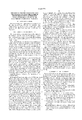
- FIGS. 1A to 1G are schematic cross-sectional views of a plate, illustrating the different stages of the method in accordance with the invention.
- reference numeral 1 schematically represents a part of a cross-section of a glass plate.
- This plate has dimensions of 27 ⁇ 44 cm and a thickness of 0.4 mm.
- By subjecting the plate to blasting with aluminum-oxide powder 300,000 conical, circular holes 3 having a maximum diameter of 300 ⁇ m and a minimum diameter of 100 ⁇ m are formed in said plate.
- the manner in which said holes are formed is described in the above-mentioned European Patent Application EP-A-562670.
- the plate is immersed in an aqueous solution of 2% HF for 2 minutes. The plate is subsequently rinsed with water and dried.
- the plate is then provided with a metal multilayer 5 (FIG. 1B) of, in succession, a first chromium layer having a thickness of 10 nm, an aluminum layer having a thickness of 5 ⁇ m and a second chromium layer having a thickness of 50 nm.
- a metal multilayer 5 (FIG. 1B) of, in succession, a first chromium layer having a thickness of 10 nm, an aluminum layer having a thickness of 5 ⁇ m and a second chromium layer having a thickness of 50 nm.
- the three metal layers are not individually represented in FIG. 1B, but as one layer 5.
- only one side of the plate is coated with a metal layer 5 and by virtue of the conical shape, also the walls of the holes 3 are internally provided with the metal layer.
- the metallized plate is immersed in EAGLETM a negative, photosensitive cataphoretic lacquer (sold by Shipley Company Inc.) dissolved in water.
- the lacquer comprises an organic polymer with alkaline amino groups which are neutralized by a water-soluble organic carboxylic acid, thereby forming a stable micro-emulsion comprising micelles having dimensions of 100 nm. These micelles are positively charged and are stabilized by an electrical double layer.
- the temperature of the lacquer is 35° C.
- the metal layer 5 is used as the cathode and a plate of stainless steel is used as the anode. A DC voltage of 100 V is applied between the anode and the cathode. Initially, the current intensity is 2 A.
- the positively charged micelles migrate towards the cathode.
- electrolysis of water takes place, resulting in the formation of hydrogen and hydroxy ions.
- the charge on the micelles is neutralized, causing said micelles to coalesce into a layer on the cathode.
- the organic layer formed is electrically insulating, so that the current through the bath decreases to substantially zero with time.
- the plate is rinsed with water and dried at 30° C.
- a lacquer coating 7 (FIG. 1C) having a thickness of 25 ⁇ m has then been formed on the metal layer 5. By virtue of the cataphoretic process, the lacquer coating 7 is deposited in a uniform thickness on the plate and in the holes.
- This lacquer coating 7 may optionally be provided with a top coating (not shown) by immersing the plate in an aqueous EAGLETM 2002 (Shipley Company Inc.) solution.
- This solution comprises cellulose. By virtue thereof, the stickiness of the lacquer coating is reduced.
- the plate is subsequently dried at 80° C.
- a photomask 9 (FIG. 1D), such as a glass plate provided with a chromium or Fe 2 O 3 pattern, is placed on the lacquer coating 7.
- the photomask comprises transparent portions 11 which are slightly larger than the holes 3 and transparent portions 13 which coincide with the portions of the metal layer to be provided with metal tracks.
- Arrows 15 denote UV-light originating from a mercury-vapour lamp. This lamp emits light having a wavelength of 365 nm. The exposure dose is 2000 mJ/cm 2 .
- a cross-linked polymer is formed which is only slightly soluble in a developing liquid.
- the lacquer coating 7 is developed by immersing it in an aqueous solution of EAGLETM DEVELOPER 2005 (Shipley Company Inc.) on the basis of lactic acid, whereafter it is rinsed with water and dried. The unexposed portions of the lacquer coating S are removed from the metal layer 5. A lacquer coating 17 remains on the metal layer in and around the holes (FIG. 1E). A lacquer coating 19 also remains in places where conductive metal tracks are to be provided.
- the uncovered metal multilayer of chromium, aluminum and chromium is etched in an aqueous solution comprising 330 g K 3 Fe(CN) 6 , 16 g NaOH and 30 g Na 3 PO 4 per litre (FIG. 1F).
- the exposed lacquer coating is stripped off by immersing the plate in acetone. After rinsing with water and drying, the plate is heated in air to 450° C. (FIG. 1G). The combustion residue is removed from the metal layer by immersing the plate for 10 seconds in an aqueous solution comprising 164.5 g Ce(NH 4 ) 2 (NO 3 ) 6 and 43 ml perchloric acid per litre. These treatments result in the lacquer coating being removed without a residue remaining. The plate is subsequently rinsed with water and dried. At this stage, the plate 1 comprises holes 3 which are internally provided with metal electrodes 21 and metal tracks 23.
- an electrically insulating substrate having many holes is reliably provided with well-conducting metal tracks on the plate and metal electrodes in the holes.
- the conductive metal used is mainly aluminum.
- the method can very suitably be used for the manufacture of selection plates and control plates for plasma displays, field-emission displays and thin electron displays.
Landscapes
- Engineering & Computer Science (AREA)
- Manufacturing & Machinery (AREA)
- Physics & Mathematics (AREA)
- General Physics & Mathematics (AREA)
- Microelectronics & Electronic Packaging (AREA)
- Structural Engineering (AREA)
- Architecture (AREA)
- Gas-Filled Discharge Tubes (AREA)
- Photosensitive Polymer And Photoresist Processing (AREA)
- Printing Plates And Materials Therefor (AREA)
- ing And Chemical Polishing (AREA)
- Cathode-Ray Tubes And Fluorescent Screens For Display (AREA)
- Manufacturing Of Printed Circuit Boards (AREA)
- Weting (AREA)
Abstract
A description is given of a method of metallizing an electrically insulating plate, for example, of glass having a large number of holes. Said holes are internally provided with a metal layer and the plate is provided with metal tracks. The metal used is mainly aluminum. The aluminum is coated with a thin protective layer of chromium, cobalt, nickel, zirconium or titanium. Said protective layer makes it possible to use a photosensitve, cataphoretic lacquer for providing the metal layer with a structure. The method can very suitably be used for the manufacture of selection plates for thin electron displays.
Description
This is a continuation of application Ser. No. 08/827,335 filed Mar. 26, 1997, now U.S. Pat. No. 5,824,454. Said application Ser. No. 08/827,335 is a continuation of application Ser. No. 08/419,588, filed Apr. 7, 1995 and now abandoned.
The invention relates to a method of photolithographically metallizing at least the inside of holes arranged in accordance with a pattern in a plate of an electrically insulating material, while using a negative, photosensitive cataphoretic lacquer coating.
Such perforated plates, for example, of glass, quartz glass, synthetic resin or a ceramic material are used, in particular, in field-emission displays and thin electron displays, the metallized holes serving as electrodes to control the electron currents moving towards the luminescent screen provided with phosphors, and the electron currents in plasma displays. The surface of such a plate also comprises narrow metal tracks which are used to drive (address) the electrodes. In such displays, the plates are used as control or selection elements. Thin electron displays comprise at least two selection plates.
Such a thin electron display is described in European Patent Application EP-A-464937, filed by Applicants. The display described therein comprises, inter alia, a preselection plate and a fine selection plate. These plates are, for example, made of glass and have a thickness of 0.5 mm. Such a plate comprises a very accurate pattern of holes, for example 400,000 holes each having a diameter of 400 μm. In and around said holes there are provided metal selection electrodes which can be individually activated by means of narrow metal tracks on the glass plate material. In said Patent Application no information is given as to which metal is used as the electrode nor how the metal is provided in and around the holes.
In European Patent Application EP-A-539714, there is disclosed an electrophoretic method of manufacturing copper patterns on printed circuit boards by using a negative, photosensitive cataphoretic lacquer. A substrate, for example, of epoxy to which a copper layer is uniformly applied is immersed in a solution of such a lacquer, the substrate and an inert electrode, for example, of stainless steel being connected to an external current source. The copper layer on the substrate serves as the cathode and the inert electrode as the anode, i.e. the copper layer is electrically connected to the negative pole of the current source. The solution of the lacquer comprises, inter alia, a mixture of a polymer comprising positively charged groups, unsaturated monomers and a photoinitiator. Examples of positively charged groups are the amino group, quaternary ammonium group, sulphonium group and sulphoxonium group. The electric field in the solution causes the positively charged mixture to be attracted towards the negatively charged copper layer where it is discharged. This results in the formation of a dense and uniform lacquer coating on the copper layer. Such a cataphoretic lacquer must be used to provide three-dimensional structures, such as internally metallized holes. The photosensitive lacquer is of the negative type, i.e. exposed parts of the lacquer coating become less soluble in a developing liquid than unexposed parts as a result of a photochemical reaction. Exposure often takes place through a photomask. This difference in solubility enables the lacquer coating to be selectively removed. The lacquer pattern formed serves as a mask for an etching agent, so that the copper layer is structured to form a desired pattern which corresponds to the photomask used.
A disadvantage of this state-of-the-art method is that copper cannot be used as a metal track or electrode in thin electron displays because of undesirable interactions with the electroluminescent phosphors used.
The metal tracks of the selection plates, for example, have a width of only 80 μm and a thickness of 5 μm. Under operating conditions, metal tracks having such a small cross-section lead to an enormous ohmic drop, over, a distance of 40 cm if an electrically ill-conducting metal is used. Examples of electrically well-conducting metals are copper and silver. Copper is unsuitable because of the above-mentioned disadvantage; silver is unattractive because it is expensive. It should be borne in mind that in order to obtain the desired pattern, the major part of the metal layer is removed by means of an etchant.
As aluminum exhibits a good electrical conductivity and a high vapour-deposition or sputtering rate, it can be used as the metal for, in particular, the metal tracks and the electrodes. It has however been found that aluminum is attacked in the known solutions of cataphoretic lacquers. If aluminum is brought into contact with a solution of a cataphoretic lacquer, gas bubbles form at the surface of the aluminum and the aluminum is dissolved in the lacquer solution. As a result, the cataphoretic lacquer coating is deposited in such a large thickness that the light used in the photolithographic step is absorbed to a substantial degree. Exposure of the lacquer coating throughout its thickness and complete curing then becomes problematic, resulting in a poor-quality photolithographic process. In addition, when the lacquer coating is provided, the gas bubbles partially dissolve in the lacquer coating, thereby forming undesirable pinholes in the lacquer coating.
It is an object of the invention to provide, inter alia, a reliable method of applying a metal coating to the walls of the holes and, preferably, also around the holes of the plates described hereinabove. The metal coating must adhere well to the plate, in particular a glass plate, and be sufficiently electroconductive for use in the narrow metal tracks on the plate, which connect the selection electrodes to the connecting contacts along the periphery of the plate.
These objects are achieved by a method as described in the opening paragraph, said method in accordance with the invention comprising the following steps:
providing a chromium layer on at least one surface of the plate and on the walls of the holes,
providing an aluminum layer on the chromium layer,
providing the aluminum layer with a metal layer, the metal being selected from the group consisting of chromium, cobalt, nickel, zirconium and titanium, or from an alloy of two or more of these metals,
electrophoretically providing a the negative, photosensitive, electrophoretic lacquer coating on the metal layer,
exposing the lacquer coating in accordance with a pattern, thereby forming exposed and unexposed portions of the lacquer coating, exposed portions being formed at least in the holes,
developing the lacquer coating, so that the metal layer underneath the unexposed portions of the lacquer layer is uncovered,
removing the uncovered metal layer and the underlying aluminum and chromium layers to the surface of the plate by means of etching, while preserving the metal, chromium and aluminum layers underneath the exposed portions of the lacquer coating,
stripping the lacquer coating of the exposed portions.
On account of its price dimensional accuracy and stability, the plate is preferably made of glass, but may alternatively be made of a ceramic or synthetic resin material. The thickness of the glass plate is, for example, 0.5 mm. The holes can be made in the plate by exposing the plate via a mask to a stream of abrasive powder particles, for example, of aluminum oxide. This method is described in European Patent Application EP-A-562670, filed by Applicants. The openings of the holes are, for example, circular in shape. Dependent upon the application of the plate, the diameter of the holes ranges from 50 μm to 5 mm. The holes formed are slightly conical, which is advantageous for the subsequent metallization of the holes.
At least one side of the plate is provided with a chromium layer. In this process, also the walls of the holes are also provided with a chromium layer. This chromium layer has a thickness, for example, of 10 nm and serves as a bonding layer for the aluminum layer to be subsequently provided.
An aluminum layer having a thickness, for example, of 5 μm is provided on the chromium layer. Because of its high evaporation or sputtering rate, aluminum can advantageously be provided by vacuum evaporation or sputtering. Aluminium is chosen because it has a high electrical conductivity and it does not have the above-mentioned disadvantages of copper and silver. The chromium layer is preferably also provided by vacuum evaporation or sputtering. Both metals can be provided one after the other by means of the same vacuum deposition system. In the vacuum evaporation or sputtering process, the surface of the plate having the largest diameter of the conical holes faces the evaporation source or sputter target. This results in this surface of the plate and the walls of the holes being coated, in succession, with a chromium layer and an aluminum layer. For certain applications, both sides of the plate are metallized.
The aluminum layer is subsequently provided with a layer of a metal selected from the group consisting of chromium, nickel, zirconium and titanium, or alloys of two or more of said metals. Unlike aluminum, these metals are not attacked by the customary, photosensitive, cataphoretic lacquers. In addition, these metals form a sealing oxide layer during further processing of the plates into a display in an oxygen- containing atmosphere at temperatures up to 450° C. Under these circumstances, non-sealing oxide layers, such as those of iron, would lead to a completely corroded metal layer. The thickness of this metal layer is, for example, 50 nm. Because of the simplicity of the process, the metal used for the layer is preferably chromium. Also this metal layer is preferably provided by vacuum evaporation or sputtering.
The metallized plate is subsequently immersed in a bath comprising a negative, photosensitive, cataphoretic lacquer. Such a lacquers is are commercially available and generally compromises a solvent, a polymer with positively charged groups, a photoinitiator and unsaturated monomers. Such a lacquer is described in the above-mentioned European Patent Application EP-A-539714. The lacquer described therein is composed, for example, of an aqueous solution of a polyaminoacrylate, diethoxy acetophenone as the photoinitiator and butyl methacrylate monomers. The metallized plate is galvanically connected to the negative pole of an external current source and serves as the cathode. The bath also comprises a plate or rod of an inert material, such as platinum or stainless steel, which serves as the anode and which is connected to the positive pole of the current source. A DC voltage, for example, of 100 V is applied cross the cathode and the anode. After a short period of time, for example thirty seconds, a photosensitive lacquer layer is deposited on the metallized plate. The plate is subsequently removed from the bath, rinsed with water and dried. Cataphoretic provision of the lacquer layer ensures that said layer is provided in a uniform thickness on the entire plate and on the walls of the holes. To preclude the formation a sticky surface, the lacquer layer may optionally be provided with a top coating. For this purpose, use can be made of coating solutions specified by the supplier of the cataphoretic lacquer, for example solutions on the basis of hydroxy cellulose. By virtue of such a top coating, it is precluded, inter alia, that the lacquer layer sticks to the photomask in the subsequent exposure step.
Owing to the presence of unsaturated monomers, the composition of the cataphoretic lacquer is such that exposure to actinic radiation results in the formation of a crosslinked network of polymers. As there is a large choice of UV-sensitive photoinitiators and exposure means, such as UV-lamps and masks, use is preferably made of UV-light, for example originating from a mercury-vapour lamp emitting light having a wavelength of 365 nm, for exposure of the lacquer coating in accordance with a pattern. Patterned exposure preferably takes place through a photomask, which is provided on the lacquer coating. In this case, the lacquer coating is preferably provided with the above-mentioned top coating to preclude sticking of the photomask to the lacquer coating. The photomask may optionally be placed at a short distance from the lacquer coating. By virtue thereof, damage to the photomask and/or the lacquer coating as well as undesired adhesion of the photomask to the sticky lacquer coating are precluded, however, the resolution is adversely affected. The photomask used only transmits UV-light in those places where the metal tracks are to be provided on the surface of the plate and where the metal electrodes are to be provided in the holes. Preferably, a narrow edge around the holes is also exposed because of the ultimately desired electrode shape.
After exposure, the lacquer coating is developed by means of a developing liquid. For this purpose, use is often made of an aqueous alkaline solution of NaOH or Na2 CO3, an aqueous lactic acid solution or a developing agent specified by the supplier of the photosensitive cataphoretic lacquer. In this process, the unexposed portions of the lacquer coating are removed and the underlying metal layer is uncovered. Following this developing process, the plate is rinsed with water.
The uncovered metal layer and the underlying aluminum and chromium layer are removed by means of well-known etching agents for these metals. Chromium and aluminum can, for example, be etched with an alkaline solution of K3 Fe(CN)6. The plate is subsequently rinsed with water.
The exposed portions of the lacquer coating are subsequently stripped off. For this purpose, use can be made of an alkaline solution as specified by the supplier of the cataphoretic lacquer. The lacquer can also be stripped off by means of an oxygen plasma.
When use is made of commercially available stripping solutions, the cataphoretic lacquer coating cannot be removed without a residue remaining from some metal surfaces, such as chromium and aluminum layers. A small quantity of the lacquer coating remains on the metal surface, which is undesirable for the further processing of the plates. A suitable method for completely removing the lacquer comprises the following steps:
the lacquer coating is largely removed, for example, by means of acetone or methyl ethyl ketone,
the plate is heated to 450° C. in air for 1 hour, so that the residual lacquer which is anchored to the metal layer is burnt,
the plate is immersed for a short period of time, for example 10 seconds, in an etching bath comprising an aqueous solution of Ce(NH4)2 (NO3)6 and perchloric acid. In this step, the combustion residue is removed from the metal layer. The immersion time is so short that the metal layer is not perceptibly attacked.
The plate is subsequently rinsed in water and dried. At this stage, the plate has been provided with metal tracks, mainly of aluminum, and electrodes, chiefly of aluminum, have also been formed on the walls of the holes.
The invention will be explained in greater detail by means of an exemplary embodiment and a drawing, in which
FIGS. 1A to 1G are schematic cross-sectional views of a plate, illustrating the different stages of the method in accordance with the invention.
The invention will now be described in greater detail with reference to the figures of the drawings.
In FIG. 1A, reference numeral 1 schematically represents a part of a cross-section of a glass plate. This plate has dimensions of 27×44 cm and a thickness of 0.4 mm. By subjecting the plate to blasting with aluminum-oxide powder, 300,000 conical, circular holes 3 having a maximum diameter of 300 μm and a minimum diameter of 100 μm are formed in said plate. The manner in which said holes are formed is described in the above-mentioned European Patent Application EP-A-562670. To remove any small aluminum-oxide particles, the plate is immersed in an aqueous solution of 2% HF for 2 minutes. The plate is subsequently rinsed with water and dried.
In a vapour deposition system, the plate is then provided with a metal multilayer 5 (FIG. 1B) of, in succession, a first chromium layer having a thickness of 10 nm, an aluminum layer having a thickness of 5 μm and a second chromium layer having a thickness of 50 nm. For the sake of simplicity, the three metal layers are not individually represented in FIG. 1B, but as one layer 5. In this example, only one side of the plate is coated with a metal layer 5 and by virtue of the conical shape, also the walls of the holes 3 are internally provided with the metal layer.
The metallized plate is immersed in EAGLE™ a negative, photosensitive cataphoretic lacquer (sold by Shipley Company Inc.) dissolved in water. The lacquer comprises an organic polymer with alkaline amino groups which are neutralized by a water-soluble organic carboxylic acid, thereby forming a stable micro-emulsion comprising micelles having dimensions of 100 nm. These micelles are positively charged and are stabilized by an electrical double layer. The temperature of the lacquer is 35° C. The metal layer 5 is used as the cathode and a plate of stainless steel is used as the anode. A DC voltage of 100 V is applied between the anode and the cathode. Initially, the current intensity is 2 A. The positively charged micelles migrate towards the cathode. At the cathode, electrolysis of water takes place, resulting in the formation of hydrogen and hydroxy ions. As a result of the alkaline medium formed, the charge on the micelles is neutralized, causing said micelles to coalesce into a layer on the cathode. The organic layer formed is electrically insulating, so that the current through the bath decreases to substantially zero with time. The plate is rinsed with water and dried at 30° C. A lacquer coating 7 (FIG. 1C) having a thickness of 25 μm has then been formed on the metal layer 5. By virtue of the cataphoretic process, the lacquer coating 7 is deposited in a uniform thickness on the plate and in the holes. This lacquer coating 7 may optionally be provided with a top coating (not shown) by immersing the plate in an aqueous EAGLE™ 2002 (Shipley Company Inc.) solution. This solution comprises cellulose. By virtue thereof, the stickiness of the lacquer coating is reduced. The plate is subsequently dried at 80° C.
A photomask 9 (FIG. 1D), such as a glass plate provided with a chromium or Fe2 O3 pattern, is placed on the lacquer coating 7. The photomask comprises transparent portions 11 which are slightly larger than the holes 3 and transparent portions 13 which coincide with the portions of the metal layer to be provided with metal tracks. Arrows 15 denote UV-light originating from a mercury-vapour lamp. This lamp emits light having a wavelength of 365 nm. The exposure dose is 2000 mJ/cm2. In the exposed areas of the lacquer coating 7 a cross-linked polymer is formed which is only slightly soluble in a developing liquid.
The lacquer coating 7 is developed by immersing it in an aqueous solution of EAGLE™ DEVELOPER 2005 (Shipley Company Inc.) on the basis of lactic acid, whereafter it is rinsed with water and dried. The unexposed portions of the lacquer coating S are removed from the metal layer 5. A lacquer coating 17 remains on the metal layer in and around the holes (FIG. 1E). A lacquer coating 19 also remains in places where conductive metal tracks are to be provided.
The uncovered metal multilayer of chromium, aluminum and chromium is etched in an aqueous solution comprising 330 g K3 Fe(CN)6, 16 g NaOH and 30 g Na3 PO4 per litre (FIG. 1F).
The exposed lacquer coating is stripped off by immersing the plate in acetone. After rinsing with water and drying, the plate is heated in air to 450° C. (FIG. 1G). The combustion residue is removed from the metal layer by immersing the plate for 10 seconds in an aqueous solution comprising 164.5 g Ce(NH4)2 (NO3)6 and 43 ml perchloric acid per litre. These treatments result in the lacquer coating being removed without a residue remaining. The plate is subsequently rinsed with water and dried. At this stage, the plate 1 comprises holes 3 which are internally provided with metal electrodes 21 and metal tracks 23.
By means of the method in accordance with the invention, an electrically insulating substrate having many holes is reliably provided with well-conducting metal tracks on the plate and metal electrodes in the holes. The conductive metal used is mainly aluminum. The method can very suitably be used for the manufacture of selection plates and control plates for plasma displays, field-emission displays and thin electron displays.
Claims (8)
1. A method of photolithographically metallizing at least the inside of holes arranged in accordance with a pattern in a plate of an electrically insulating material, while using a negative, photosensitive cataphoteric lacquer coating, characterized in that the method comprises the following steps:
a) providing a chromium layer on at least one surface of the plate and on the walls of the holes:
b) providing an aluminum layer on the chromium layer:
c) providing the aluminum layer with an additional layer, the metal of the additional layer being selected from the group consisting of chromium, cobalt, nickel, zirconium and titanium and alloys of two or more of said metals;
d) electrophoretically providing the negative, photosensitive lacquer coating on the additional metal layer;
e) exposing the lacquer coating in accordance with a pattern, thereby forming exposed and unexposed portions of the lacquer coating, exposed portions being formed at least in the holes;
f) developing the lacquer coating so that those portions of the additional metal layer that are underneath the unexposed portions of the lacquer layer are uncovered;
g) removing the uncovered additional metal layer and the underlying aluminum and chromium layers to the surface of the plate by etching, while preserving the additional metal layer and the chromium and aluminum layers that are underneath the exposed portions of the lacquer coating and
h) stripping the lacquer coating of the exposed portions.
2. A method as claimed in claim 1, characterized in that the chromium and aluminum layers are provided by vacuum evaporation or sputtering.
3. A method as claimed in claim 1, characterized in that the layer of the additional metal is chromium.
4. A method as claimed in claim 3, characterized in that the lacquer coating is stripped by treating it with an aqueous solution of Ce(NH4)2 (NO3)6 and perchloric acid.
5. A method as claimed in claim 1, characterized in that a cataphoretic lacquer coating sensitive to UV radiation is used.
6. A method as claimed in claim 1, characterized in that patterned exposure is carried out through a mask.
7. A method as claimed in claim 1, characterized in that the plate is a selection plate for a thin electron display, the chromium, aluminum and additional metal layers forming electrodes on the wall of the holes electrodes.
8. A method as claimed in claim 1, characterized in that glass is used as the electrically insulating material of the plate.
Priority Applications (1)
| Application Number | Priority Date | Filing Date | Title |
|---|---|---|---|
| US09/017,093 US6045979A (en) | 1994-04-12 | 1998-02-02 | Method of photolithographically metallizing at least the inside of holes arranged in accordance with a pattern in a plate of an electrically insulating material |
Applications Claiming Priority (5)
| Application Number | Priority Date | Filing Date | Title |
|---|---|---|---|
| EP94200976 | 1994-04-12 | ||
| EP94200976 | 1994-04-12 | ||
| US41958895A | 1995-04-07 | 1995-04-07 | |
| US08/827,335 US5824454A (en) | 1994-04-12 | 1997-03-26 | Method of photolithographically metallizing at least the inside of holes arranged in accordance with a pattern in a plate of an electrically insulating material |
| US09/017,093 US6045979A (en) | 1994-04-12 | 1998-02-02 | Method of photolithographically metallizing at least the inside of holes arranged in accordance with a pattern in a plate of an electrically insulating material |
Related Parent Applications (1)
| Application Number | Title | Priority Date | Filing Date |
|---|---|---|---|
| US08/827,335 Continuation US5824454A (en) | 1994-04-12 | 1997-03-26 | Method of photolithographically metallizing at least the inside of holes arranged in accordance with a pattern in a plate of an electrically insulating material |
Publications (1)
| Publication Number | Publication Date |
|---|---|
| US6045979A true US6045979A (en) | 2000-04-04 |
Family
ID=8216788
Family Applications (2)
| Application Number | Title | Priority Date | Filing Date |
|---|---|---|---|
| US08/827,335 Expired - Fee Related US5824454A (en) | 1994-04-12 | 1997-03-26 | Method of photolithographically metallizing at least the inside of holes arranged in accordance with a pattern in a plate of an electrically insulating material |
| US09/017,093 Expired - Fee Related US6045979A (en) | 1994-04-12 | 1998-02-02 | Method of photolithographically metallizing at least the inside of holes arranged in accordance with a pattern in a plate of an electrically insulating material |
Family Applications Before (1)
| Application Number | Title | Priority Date | Filing Date |
|---|---|---|---|
| US08/827,335 Expired - Fee Related US5824454A (en) | 1994-04-12 | 1997-03-26 | Method of photolithographically metallizing at least the inside of holes arranged in accordance with a pattern in a plate of an electrically insulating material |
Country Status (5)
| Country | Link |
|---|---|
| US (2) | US5824454A (en) |
| EP (1) | EP0702806B1 (en) |
| JP (1) | JPH08512170A (en) |
| DE (1) | DE69508019T2 (en) |
| WO (1) | WO1995027924A1 (en) |
Families Citing this family (12)
| Publication number | Priority date | Publication date | Assignee | Title |
|---|---|---|---|---|
| DE69508019T2 (en) * | 1994-04-12 | 1999-09-16 | Koninklijke Philips Electronics N.V., Eindhoven | METHOD FOR PHOTOLITHOGRAPHIC METALLIZING AT LEAST ON THE INSIDE OF HOLES APPLIED IN CONNECTION WITH A PATTERN CONTAINING A PLATE CONTAINING ELECTRICALLY ISOLATING MATERIAL |
| US7167155B1 (en) | 1995-07-20 | 2007-01-23 | E Ink Corporation | Color electrophoretic displays |
| US7109968B2 (en) | 1995-07-20 | 2006-09-19 | E Ink Corporation | Non-spherical cavity electrophoretic displays and methods and materials for making the same |
| US7071913B2 (en) | 1995-07-20 | 2006-07-04 | E Ink Corporation | Retroreflective electrophoretic displays and materials for making the same |
| JP2000505151A (en) * | 1996-11-21 | 2000-04-25 | コーニンクレッカ フィリップス エレクトロニクス エヌ ヴィ | Method of providing a silver layer on a glass substrate |
| US6839158B2 (en) | 1997-08-28 | 2005-01-04 | E Ink Corporation | Encapsulated electrophoretic displays having a monolayer of capsules and materials and methods for making the same |
| US7075502B1 (en) | 1998-04-10 | 2006-07-11 | E Ink Corporation | Full color reflective display with multichromatic sub-pixels |
| US6842657B1 (en) | 1999-04-09 | 2005-01-11 | E Ink Corporation | Reactive formation of dielectric layers and protection of organic layers in organic semiconductor device fabrication |
| US7038655B2 (en) | 1999-05-03 | 2006-05-02 | E Ink Corporation | Electrophoretic ink composed of particles with field dependent mobilities |
| KR100669451B1 (en) * | 2000-02-15 | 2007-01-15 | 삼성에스디아이 주식회사 | How to form black matrix etchant and black matrix |
| WO2003032334A1 (en) * | 2001-09-10 | 2003-04-17 | Noritake Co., Limited | Thick-film sheet member, its applied device, and methods for manufacturing them |
| WO2003050607A1 (en) | 2001-12-13 | 2003-06-19 | E Ink Corporation | Electrophoretic electronic displays with films having a low index of refraction |
Citations (1)
| Publication number | Priority date | Publication date | Assignee | Title |
|---|---|---|---|---|
| US5824454A (en) * | 1994-04-12 | 1998-10-20 | U.S. Philips Corporation | Method of photolithographically metallizing at least the inside of holes arranged in accordance with a pattern in a plate of an electrically insulating material |
Family Cites Families (5)
| Publication number | Priority date | Publication date | Assignee | Title |
|---|---|---|---|---|
| JPS5821257B2 (en) * | 1974-04-25 | 1983-04-28 | 富士写真フイルム株式会社 | Red-spotted moth |
| US4180604A (en) * | 1977-12-30 | 1979-12-25 | International Business Machines Corporation | Two layer resist system |
| JPS5858546A (en) * | 1981-10-02 | 1983-04-07 | Kimoto & Co Ltd | Photosensitive mask material for photoengraving |
| JPS61206293A (en) * | 1985-03-08 | 1986-09-12 | 日本ペイント株式会社 | Manufacture of circuit board |
| JPH0281048A (en) * | 1988-09-19 | 1990-03-22 | Hoya Corp | Method and material for forming pattern |
-
1995
- 1995-04-04 DE DE69508019T patent/DE69508019T2/en not_active Expired - Fee Related
- 1995-04-04 EP EP95912388A patent/EP0702806B1/en not_active Expired - Lifetime
- 1995-04-04 JP JP7526211A patent/JPH08512170A/en not_active Ceased
- 1995-04-04 WO PCT/IB1995/000231 patent/WO1995027924A1/en not_active Ceased
-
1997
- 1997-03-26 US US08/827,335 patent/US5824454A/en not_active Expired - Fee Related
-
1998
- 1998-02-02 US US09/017,093 patent/US6045979A/en not_active Expired - Fee Related
Patent Citations (1)
| Publication number | Priority date | Publication date | Assignee | Title |
|---|---|---|---|---|
| US5824454A (en) * | 1994-04-12 | 1998-10-20 | U.S. Philips Corporation | Method of photolithographically metallizing at least the inside of holes arranged in accordance with a pattern in a plate of an electrically insulating material |
Also Published As
| Publication number | Publication date |
|---|---|
| JPH08512170A (en) | 1996-12-17 |
| EP0702806B1 (en) | 1999-03-03 |
| WO1995027924A1 (en) | 1995-10-19 |
| US5824454A (en) | 1998-10-20 |
| EP0702806A1 (en) | 1996-03-27 |
| DE69508019D1 (en) | 1999-04-08 |
| DE69508019T2 (en) | 1999-09-16 |
Similar Documents
| Publication | Publication Date | Title |
|---|---|---|
| US5744283A (en) | Method of photolithographically metallizing at least the inside of holes arranged in accordance with a pattern in a plate of an electrically insulating material | |
| EP0706678B1 (en) | Method of photolithographically producing a copper pattern on a plate of an electrically insulating material | |
| US6045979A (en) | Method of photolithographically metallizing at least the inside of holes arranged in accordance with a pattern in a plate of an electrically insulating material | |
| US5004672A (en) | Electrophoretic method for applying photoresist to three dimensional circuit board substrate | |
| US4022927A (en) | Methods for forming thick self-supporting masks | |
| US2443119A (en) | Process of producing predetermined metallic patterns | |
| US4200668A (en) | Method of repairing a defective photomask | |
| JPS632398A (en) | Method of forming metal original die | |
| US5314789A (en) | Method of forming a relief image comprising amphoteric compositions | |
| US4966664A (en) | Method for removing photoresist | |
| US3619285A (en) | Method of making a patterned metal film article | |
| US5202222A (en) | Selective and precise etching and plating of conductive substrates | |
| US3240684A (en) | Method of etching rhodium plated metal layers and of making rhodium plated printed circuit boards | |
| US5269890A (en) | Electrochemical process and product therefrom | |
| US5098527A (en) | Method of making electrically conductive patterns | |
| EP0425437A2 (en) | Method for making metallic patterns | |
| US5755947A (en) | Adhesion enhancement for underplating problem | |
| US5073478A (en) | Method of making a pattern | |
| JPH0136557B2 (en) | ||
| US20180054899A1 (en) | Circuit board and method of forming same | |
| EP0467945A1 (en) | Printed circuit boards. | |
| CA1333578C (en) | Production of metallic patterns | |
| US4172757A (en) | Process for making electrode with integral dielectric layer | |
| JPH10140399A (en) | Pattern formation method | |
| JPH06104554A (en) | Manufacture of electric-circuit trace |
Legal Events
| Date | Code | Title | Description |
|---|---|---|---|
| FPAY | Fee payment |
Year of fee payment: 4 |
|
| REMI | Maintenance fee reminder mailed | ||
| LAPS | Lapse for failure to pay maintenance fees | ||
| STCH | Information on status: patent discontinuation |
Free format text: PATENT EXPIRED DUE TO NONPAYMENT OF MAINTENANCE FEES UNDER 37 CFR 1.362 |
|
| FP | Lapsed due to failure to pay maintenance fee |
Effective date: 20080404 |