US604466A - Electric meter - Google Patents
Electric meter Download PDFInfo
- Publication number
- US604466A US604466A US604466DA US604466A US 604466 A US604466 A US 604466A US 604466D A US604466D A US 604466DA US 604466 A US604466 A US 604466A
- Authority
- US
- United States
- Prior art keywords
- armature
- meter
- coil
- volt
- coils
- Prior art date
- Legal status (The legal status is an assumption and is not a legal conclusion. Google has not performed a legal analysis and makes no representation as to the accuracy of the status listed.)
- Expired - Lifetime
Links
- XEEYBQQBJWHFJM-UHFFFAOYSA-N Iron Chemical group [Fe] XEEYBQQBJWHFJM-UHFFFAOYSA-N 0.000 description 11
- 230000001939 inductive effect Effects 0.000 description 7
- 230000005389 magnetism Effects 0.000 description 6
- 239000004411 aluminium Substances 0.000 description 4
- XAGFODPZIPBFFR-UHFFFAOYSA-N aluminium Chemical compound [Al] XAGFODPZIPBFFR-UHFFFAOYSA-N 0.000 description 4
- 229910052782 aluminium Inorganic materials 0.000 description 4
- 239000010437 gem Substances 0.000 description 3
- 229910001751 gemstone Inorganic materials 0.000 description 3
- 230000005415 magnetization Effects 0.000 description 3
- IRLPACMLTUPBCL-KQYNXXCUSA-N 5'-adenylyl sulfate Chemical compound C1=NC=2C(N)=NC=NC=2N1[C@@H]1O[C@H](COP(O)(=O)OS(O)(=O)=O)[C@@H](O)[C@H]1O IRLPACMLTUPBCL-KQYNXXCUSA-N 0.000 description 1
- RYGMFSIKBFXOCR-UHFFFAOYSA-N Copper Chemical compound [Cu] RYGMFSIKBFXOCR-UHFFFAOYSA-N 0.000 description 1
- 102000001839 Neurturin Human genes 0.000 description 1
- 108010015406 Neurturin Proteins 0.000 description 1
- 238000010276 construction Methods 0.000 description 1
- 239000010949 copper Substances 0.000 description 1
- 229910052802 copper Inorganic materials 0.000 description 1
- 230000003028 elevating effect Effects 0.000 description 1
- 230000002452 interceptive effect Effects 0.000 description 1
- 229910052742 iron Inorganic materials 0.000 description 1
- 230000003472 neutralizing effect Effects 0.000 description 1
- 230000001846 repelling effect Effects 0.000 description 1
- 238000004804 winding Methods 0.000 description 1
Images


Classifications
-
- G—PHYSICS
- G01—MEASURING; TESTING
- G01R—MEASURING ELECTRIC VARIABLES; MEASURING MAGNETIC VARIABLES
- G01R11/00—Electromechanical arrangements for measuring time integral of electric power or current, e.g. of consumption
- G01R11/36—Induction meters, e.g. Ferraris meters
Definitions
- My invention relates to improvements in integratingwattmeters for, measuring alternating electric currents, and particularly to that class known as motor-meters.
- the objects of my invention are to provide a meter that is sensitive and efficient upon small loads, adapted for a convenient adjustment for neutralizing the friction'of its bearings when in operation, capable of measuring accurately large capacities and yet adapted to measure on less than one-half of one per centum of its total capacity, and that will measure inductive loads.
- Another object is to provide a compensating device for balancing the friction and iiiertiaso constructed and arrangedas to be adjustable to suit the pressure at the point of utility.
- the novel feature of my invention consists in the construction, arrangement, and combination of the series coils, the laminated core therefor, the aluminium armature, the shunt or volt coil, the compensating device, and the magneto-electric drag.
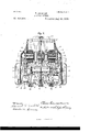
- Figure 1 is a front elevation of my invention, showing the general arrangement of the parts thereof.
- Fig. 2 is a similar view of the same, with the operative parts shown in vertical section.
- Fig. 3 is a side elevation of the same.
- Figs. 4 and 5 are sectional views taken horizontally through themotive part.
- Fig. 5 also showsthe compensating device adjusted to one side to counterbalance the friction of the moving parts of the meter.
- Figs. 6 and 7 are details of the revoluble armature, with the compensating device mounted in position ad- 3' acent thereto.
- Fig. 1 is a front elevation of my invention, showing the general arrangement of the parts thereof.
- Fig. 2 is a similar view of the same, with the operative parts shown in vertical section.
- Fig. 3 is a side elevation of the same.
- Figs. 4 and 5 are sectional views taken horizontally through themotive part.
- Fig. 5 also showsthe compensating device adjusted to
- Fig. 8 shows the volt-coil and core removed to show the adjusting-screws 28 and 29.
- Fig. 9 shows the compensator moved to the left to assist in producing rotation of the cylindrical armature.
- Fig. 10 shows the compensating device wound with a wire and in series with a proper resistance by the variation of which the desired starting torque may be obtained.
- Fig. 11 shows the said resistance employed with variable contacts, such as are used in ordinary rheostats.
- Fig. 12 shows the employment of two compensating devices in diametric arrangement outside of the cylinder.
- Fig. 13 illustrates diagrammatically the action of the compensating device upon the armature in producing or accelerating rotation thereof.
- Fig. 14 shows a diametric core arranged in combination with a multipolar series field.
- Fig. 15 shows the employment of a four-pole field and four-pole volt-coil.
- Fig. 16 shows an arrangement of series coils upon the inside of the cylindrical armature and the volt-coils upon the outside thereof.
- Fig. 17 shows a similar arrangement of the series coils inside of the armature and the multipolar volt-coils outside thereof.
- Fig. 18 differs from Fig. 17 in having the shunt-coil embracing the armature.
- Fig. 19 shows both the series and volt coils mounted without the armature.
- Figs. 20 and 21 show the series coils without the use of an iron core and with two and four pole volt-coils, respectively.
- the operative parts of my invention are mounted within and upon the two-part cast metallic sheath 1, having a forwardly-projecting base 2, semicircular in contour and provided with an upright flange 3, which is a continuation of the opposite integral sides 4.
- the central hub 28 of said disk has a pendent annular lug concentric with the spindle, whereby by elevating said thumb-nut to contact with the pendent portion of said hub and then rotating the same the armature-spindle will be elevated out of contact with said jewel-bearing, which is desirable in transportation.
- the armature-spindle has upon its upper end a proper Worm 29, adapted to form an actuating engagement with the said registering-train.
- the cylindrical armature 30, preferably of aluminium, has a closed top provided with a concentric hub 31. This armature is rigidly fixed to said spindle 20 by a proper set-screw in said hub and is arranged between the ends of said core 17 and in close proximity thereto.
- a volt-coil 32 rigidly sup- 36, upon which the volt-coil 32 is wound.
- the forwardly-projecting arm 37 To the lower end of said tube 35 is clamped or otherwise mounted the forwardly-projecting arm 37, on the forward end of which is mounted the compensating device 38, which is arranged immediately adjacent and in close proximity to the front face of said armature.
- the compensating device 38 As the arm 37 is pivotally mounted on said tube, the compensating device 38 is adapted for a lateral adjustment to any desired position in front of the armature.
- This compensating device is formed of an iron core 39 and a closed circuit or secondary 4.0, the secondary being preferably apiece of copper tubing.
- an impedance-coil 41 having an iron core 42 and an adjustable part 43, which is separated from the said coil and said core by a wooden piece 145.
- the impedance-coil th-us'arranged is supported in position by a proper holding-screw 4.5, Fig. 3.
- Another coil 47 of less turns than those of the said volt-coil and of larger wire, is wound upon the said iron core 36, and has a resistance 46 in series with it, as shown diagrammatically in Figs. 4 and 5.
- the two remaining or outer terminals of the impedancecoil and volt-coil are connected to the two leads of the system, as shown in Fig. 4.
- the torque thus produced will vary as the energy through the meter; but a load or drag must be applied, so that the speed will also vary as the torque or energy.
- This function is accomplished by the said aluminium disk 27 ,rotating between the poles of the permanent magnets 2a in a well-understood manner.
- the magnetism of the volt-coil 36 should be exactly in quadrature with the electromotive force of the circuit.
- This is accomplished by the employment of the said secondary coil or winding 47, which is short-circuited through a resistance 46. Assuming that the current through the volt-coil circuit lags less than ninety degrees behindlthe electromotive force, the resistance 46 may be adjusted until the current in the secondary 47, acting in conjunction with that in the volt-coils 32, forms a resultant field through the iron core 36, which acts upon the cylindrical ,armature,and is in quadrature to the electromotive force.
- the secondary coil 47 may have more than one layer, as shown in Fig. 5.
- the compensating device may be square in form instead of circular, as shown in Fig. 7 lVhen the said compensating device is equidistant from the oppositely-arranged field-coils, as in Fig. 8, it has no tendency to produce motion in the adjacent armature.
- the compensator is adjusted just far enough to counterbalance or neutralize the friction and inertia of the moving parts of the meter, after which the meter will operate or start up on a very small amount of energy.
- the compensator may be set at the maximum angle, which is about thirty to forty degrees, when by varying the resistance 46 the desired starting torque may be obtained.
- a pair of compensators arranged diametrically of said armature is shown in Fig. 12.
- the action of the said compensator is illustrated diagrammatically in Fig. 13. Assume that the magnetism through the core 36 produces the poles N and S at any given instant, and in the absence of the compensator 38 said magnetism, we will assume, would tend to follow the line 00; but on account of said compensator the magnetism will be diverted or drawn in the direction of the line 3 through the cylindrical armature, thereby inducing in said armature eddy-currents, which will give the poles n and 8.
- the magnetism After the magnetism has passed through the armature it will enter the compensator, as shown by the line 2, being drawn by the iron core 39, Figs. 10 and 11, thereby also inducing currents in the closed circuit which gives the poles n s.
- the pole N of the core 36 repelling the pole n of the revoluble armature and n of the compensator attracting s of the armature.
- the poles n and n are opposite or facing N on account of the lag and self-induction of the eddy-currents producing them.
- a compensating device 38 comprising an iron core 39 and a secondary 4:0, and means for adjusting the same, the said device being adapted for an angular adjustment relative to the armature, and is adapted to neutralize the friction and inertia of the moving parts of the meter, all substantially as described.
- a motor-meter the combination of a series field traversed by the main current; a revoluble armature in inductive relation to said field; and an adjustable compensating device 38 adapted to counterbalance or neutralize the friction and inertia of the moving parts of the meter, and comprising an iron core fixed upon a pivoted supporting-arm and a secondary 40 in cooperative relation with said armature.
Landscapes
- Physics & Mathematics (AREA)
- General Physics & Mathematics (AREA)
- Manufacture Of Motors, Generators (AREA)
Description
(No Model.) 7 Sheets-Sheet l.
T. D UN 0 AN. ELECTRIC METER.
N0. 604,466. Patented May 24, 1898.
Fig. 1.
KILOWATT uoun s AMPS. voLTs.
INTEGRATING WATT METER.
& a 3313 4; abtozwu s (No Model.) 7 SheetsSheet 2 T. DUNCAN. ELECTRIC METER.
No. 604,466. Patented May 24,1898.
(No Model.) 7 SheetsSheet 3.
T. DUNCAN. ELECTRIC METER.
Patented May 24,1898.
79 WSVWQVVEQ:
(No Model.) 7 SheetsSheet 4.
T. DUNCAN.
. ELECTRIC METER. 6 No. 604,466. Patented May 24,1898.
Fig 4.
LJ\ N v 7 Q 52 46 O 3 7 WM meme/o 'woewtoz @WM/ QM w a axle/11w 1d (No Model.) 7 Sheets-Sheet 5,
T. DUNG AN. ELECTRIC METER.
No. 604,466. Patented May 24,1898.
Fig. (9.
1 9176 neooeo (No Model.) 7 Sheets-Sheet 6.
' T. DUNCAN.
ELECTRIC METER.
Patented May 24 Fig. 15.
(No Model.) 7 Sheets-Sheet 7.
T. DUNCAN.
ELEGTRIG METER.
No. 604,466. Patented May 24,1898.
g w W wwvmwo @2443 Mfloewtoz MM @15 fi GWMMM SW M QaAa/Ma @i/W.
NrTn STATES Enron.
PATENT .ELECTRlC METER.
SPECIFICATION forming part of Letters Patent No. 604,466, dated May 24, 1898.
Application filed November 1897. Serial No. 657,730. (No model.)
tion, which will enable others skilled in the art to which it appertains to make and use the same, reference being had to the accompanying drawings, which form part ofthis specification.
My invention relates to improvements in integratingwattmeters for, measuring alternating electric currents, and particularly to that class known as motor-meters.
The objects of my invention are to provide a meter that is sensitive and efficient upon small loads, adapted for a convenient adjustment for neutralizing the friction'of its bearings when in operation, capable of measuring accurately large capacities and yet adapted to measure on less than one-half of one per centum of its total capacity, and that will measure inductive loads.
Another object is to provide a compensating device for balancing the friction and iiiertiaso constructed and arrangedas to be adjustable to suit the pressure at the point of utility.
The novel feature of my invention consists in the construction, arrangement, and combination of the series coils, the laminated core therefor, the aluminium armature, the shunt or volt coil, the compensating device, and the magneto-electric drag.
In the accompanying drawings, in which similar reference numerals and letters indicate like parts throughout the several views, Figure 1 is a front elevation of my invention, showing the general arrangement of the parts thereof. Fig. 2 is a similar view of the same, with the operative parts shown in vertical section. Fig. 3 is a side elevation of the same. Figs. 4 and 5 are sectional views taken horizontally through themotive part. Fig. 5 also showsthe compensating device adjusted to one side to counterbalance the friction of the moving parts of the meter. Figs. 6 and 7 are details of the revoluble armature, with the compensating device mounted in position ad- 3' acent thereto. Fig. 8 shows the volt-coil and core removed to show the adjusting- screws 28 and 29. Fig. 9 shows the compensator moved to the left to assist in producing rotation of the cylindrical armature. Fig. 10 shows the compensating device wound with a wire and in series with a proper resistance by the variation of which the desired starting torque may be obtained. Fig. 11 shows the said resistance employed with variable contacts, such as are used in ordinary rheostats. Fig. 12 shows the employment of two compensating devices in diametric arrangement outside of the cylinder. Fig. 13 illustrates diagrammatically the action of the compensating device upon the armature in producing or accelerating rotation thereof. Fig. 14 shows a diametric core arranged in combination with a multipolar series field. Fig. 15 shows the employment of a four-pole field and four-pole volt-coil. Fig. 16 shows an arrangement of series coils upon the inside of the cylindrical armature and the volt-coils upon the outside thereof. Fig. 17 shows a similar arrangement of the series coils inside of the armature and the multipolar volt-coils outside thereof. Fig. 18 differs from Fig. 17 in having the shunt-coil embracing the armature. Fig. 19 shows both the series and volt coils mounted without the armature. Figs. 20 and 21 show the series coils without the use of an iron core and with two and four pole volt-coils, respectively.
The operative parts of my invention are mounted within and upon the two-part cast metallic sheath 1, having a forwardly-projecting base 2, semicircular in contour and provided with an upright flange 3, which is a continuation of the opposite integral sides 4.
The meetingedges of said sh'eatlnsections upright flanges 10, having suitable perforations 11, by which the said sheath is rigidly secured in position upon a proper support. In a suitable vertical opening in said flange 7 midway its ends and near its outer edge is arranged a bearing 8 for the upper end of the armature-spindle, Figs. 2 and 3. In the lower portion of said sheath and adjacent to the back thereof is properly secured an upright insulating-board 12. To the outer face of said board 12 and near the opposite sides thereof are fixed the outer binding-posts l3 and the inner binding-posts 14:, which are connected by the cross-bar 15. To the free end and lower face of the said arms 9 are rigidly secured by means of the screws 16 the ends of the laminated core 17, Figs. 2 and 4. On the adjacent ends of said core are mounted the series coils 18. In a central screw-threaded openingin the base of said sheath is mounted the screw 19, Whose upper end is centrally apertured for the conical lower end of the armature-spindle 20, and has a proper jewelbearing 21 arranged in a horizontal central slot therein and supported upon a suitable spiral spring 22, adapted to take the jar off of the said jewel in handling or in transportation. In this jewel 21 is mounted the lower conical end of the armature spindle. A thumb-nut 23, Fig. 2, having its upper end centrally apertured to admit the lower end of said spindle, is arranged upon the upper portion of said screw 19. The head of said screw 19 is contained in the pendent pocket 6, in which, after adjustment, it is securely sealed. On the base 2 of said sheath 1 are arranged the permanent magnets 24:, which are mounted in the respective clamps 25. These clamps are rigidly secured in position by the holding-screws 26, the heads of which are arranged in the pockets 6, and when adj usted are properly sealed therein. An aluminium disk 27, adapted for rotation between the poles of the said permanent magnets to make the speed of the meter proportional to the energy passing through the same in a wellunderstood manner, is mounted upon said armature-spindle adjacent to the upper end of said thumb-nut and is secured in position by a proper set-screw. The central hub 28 of said disk has a pendent annular lug concentric with the spindle, whereby by elevating said thumb-nut to contact with the pendent portion of said hub and then rotating the same the armature-spindle will be elevated out of contact with said jewel-bearing, which is desirable in transportation. The armature-spindle has upon its upper end a proper Worm 29, adapted to form an actuating engagement with the said registering-train. The cylindrical armature 30, preferably of aluminium, has a closed top provided with a concentric hub 31. This armature is rigidly fixed to said spindle 20 by a proper set-screw in said hub and is arranged between the ends of said core 17 and in close proximity thereto. Within the armature is arranged a volt-coil 32, rigidly sup- 36, upon which the volt-coil 32 is wound.
To the lower end of said tube 35 is clamped or otherwise mounted the forwardly-projecting arm 37, on the forward end of which is mounted the compensating device 38, which is arranged immediately adjacent and in close proximity to the front face of said armature. As the arm 37 is pivotally mounted on said tube, the compensating device 38 is adapted for a lateral adjustment to any desired position in front of the armature. This compensating device is formed of an iron core 39 and a closed circuit or secondary 4.0, the secondary being preferably apiece of copper tubing.
To the back of the sheath 1, near the top thereof, is arranged an impedance-coil 41, having an iron core 42 and an adjustable part 43, which is separated from the said coil and said core by a wooden piece 145. The impedance-coil th-us'arranged is supported in position by a proper holding-screw 4.5, Fig. 3. Another coil 47, of less turns than those of the said volt-coil and of larger wire, is wound upon the said iron core 36, and has a resistance 46 in series with it, as shown diagrammatically in Figs. 4 and 5. The two remaining or outer terminals of the impedancecoil and volt-coil are connected to the two leads of the system, as shown in Fig. 4.
The operation of the improved meter is, briefly stated, as follows: When an impulse of current traverses the series coils 18, Fig. i, a line of magnetism is set up in the horizontal. Another impulse of current also traverses the volt-coil 32; but because of its own self-induction and that of the impedance-coil in series with it its current lags behind that in the series coils, thereby setting up at right angles or the vertical,another line of magnetization lagging behind the said line of magnetization set up by the series coils. These two lines of magnetization form a resultant which actuates the cylindrical armature in a Well-understood manner. The torque thus produced will vary as the energy through the meter; but a load or drag must be applied, so that the speed will also vary as the torque or energy. This function is accomplished by the said aluminium disk 27 ,rotating between the poles of the permanent magnets 2a in a well-understood manner.
When it is desired to measure inductive loads with my improved meter, it is necessary that the magnetism of the volt-coil 36 should be exactly in quadrature with the electromotive force of the circuit. This is accomplished by the employment of the said secondary coil or winding 47, which is short-circuited through a resistance 46. Assuming that the current through the volt-coil circuit lags less than ninety degrees behindlthe electromotive force, the resistance 46 may be adjusted until the current in the secondary 47, acting in conjunction with that in the volt-coils 32, forms a resultant field through the iron core 36, which acts upon the cylindrical ,armature,and is in quadrature to the electromotive force. The secondary coil 47 may have more than one layer, as shown in Fig. 5.
The compensating device may be square in form instead of circular, as shown in Fig. 7 lVhen the said compensating device is equidistant from the oppositely-arranged field-coils, as in Fig. 8, it has no tendency to produce motion in the adjacent armature. By adjusting the said compensator to the side in which rotation is desired or that in which the meter normally rot-ates the motion of the armature is accelerated, depending upon the adjustment of said compensator.
In practice the compensator is adjusted just far enough to counterbalance or neutralize the friction and inertia of the moving parts of the meter, after which the meter will operate or start up on a very small amount of energy.
When a meter is adjusted for simply overcoming the friction of its working parts in a laboratory, where there is no perceptible vibration and is then placed or installed in a location where it is subjected to vibration ,it will run fast or creep, because such vibration tends to overcome the friction of its working parts. Therefore the meter will operate more or less when no energy is being used by theconsumer. In my present improved meter this difficulty is entirely overcome by the use of the said compensating device,for by its use creeping is prevented, and each meter can be adjusted to meet the conditions of its situation or environment without in the least interfering with the torque on any load.
Asshown in Fig. 10, the compensator may be set at the maximum angle, which is about thirty to forty degrees, when by varying the resistance 46 the desired starting torque may be obtained. A pair of compensators arranged diametrically of said armature is shown in Fig. 12. The action of the said compensator is illustrated diagrammatically in Fig. 13. Assume that the magnetism through the core 36 produces the poles N and S at any given instant, and in the absence of the compensator 38 said magnetism, we will assume, would tend to follow the line 00; but on account of said compensator the magnetism will be diverted or drawn in the direction of the line 3 through the cylindrical armature, thereby inducing in said armature eddy-currents, which will give the poles n and 8. After the magnetism has passed through the armature it will enter the compensator, as shown by the line 2, being drawn by the iron core 39, Figs. 10 and 11, thereby also inducing currents in the closed circuit which gives the poles n s. From the above conditions we have the pole N of the core 36 repelling the pole n of the revoluble armature and n of the compensator attracting s of the armature. The poles n and n are opposite or facing N on account of the lag and self-induction of the eddy-currents producing them.
Practical tests have demonstrated that my present compensator is far more powerful and efficient than the compensator shown and described in a prior patent granted to me on the 15th day of December, 1896, numbered 573,078 and consisting of an iron pin.
Having thus described my invention and the manner of operating the same, what I desire to secure by Letters Patent is 1. In an electric-motor meter the combination of a series field representing the main current; a revoluble armature in inductive relation to said field; a volt coil or coils arranged in inductive relation to said armature; a secondary coil closed through a suitable resistance and acting inductively in cooperation with the said volt coil or coils upon the said armature; and a compensating device comprising an iron core 39 and a closed circuit or secondary 40, the said compensator being adapted for adjustment relative to said armature for the purpose specified, substantially as described.
2. In an electric-motor meter, a compensating device 38 comprising an iron core 39 and a secondary 4:0, and means for adjusting the same, the said device being adapted for an angular adjustment relative to the armature, and is adapted to neutralize the friction and inertia of the moving parts of the meter, all substantially as described.
3. In a motor-meter, the combination of a series field traversed by the main current; a revoluble armature in inductive relation to said field; and an adjustable compensating device 38 adapted to counterbalance or neutralize the friction and inertia of the moving parts of the meter, and comprising an iron core fixed upon a pivoted supporting-arm and a secondary 40 in cooperative relation with said armature.
Signed by me, at Fort Wayne, Allen county, State of Indiana, this 5th day of November,
Witnesses:
ADELAIDE KEARNS, WATTS P. DENNY.
Publications (1)
| Publication Number | Publication Date |
|---|---|
| US604466A true US604466A (en) | 1898-05-24 |
Family
ID=2673095
Family Applications (1)
| Application Number | Title | Priority Date | Filing Date |
|---|---|---|---|
| US604466D Expired - Lifetime US604466A (en) | Electric meter |
Country Status (1)
| Country | Link |
|---|---|
| US (1) | US604466A (en) |
-
0
- US US604466D patent/US604466A/en not_active Expired - Lifetime
Similar Documents
| Publication | Publication Date | Title |
|---|---|---|
| US2090521A (en) | Accelerometer | |
| US604466A (en) | Electric meter | |
| US611809A (en) | eyershed | |
| US604459A (en) | Electric meter | |
| US675996A (en) | Electric meter. | |
| US551436A (en) | Electric meter | |
| US1474965A (en) | Electricity-metering system | |
| US652454A (en) | Alternating-current electric meter. | |
| US1010271A (en) | Induction-meter. | |
| US787256A (en) | Direct-current meter. | |
| US596190A (en) | Induction-wattmeter | |
| US604463A (en) | Electric meter | |
| US698639A (en) | Electric meter. | |
| US1226946A (en) | Speedometer. | |
| US573078A (en) | Wattmeter | |
| US835322A (en) | Electric measuring instrument. | |
| US652453A (en) | Alternating-current electric meter. | |
| US614225A (en) | Electric meter | |
| US397966A (en) | Electric-current indicator | |
| US635159A (en) | Electric meter. | |
| US624141A (en) | white | |
| US604465A (en) | Electric meter | |
| US869602A (en) | Electrical apparatus. | |
| US1745868A (en) | Electrical measuring instrument | |
| US371559A (en) | Eichaed n |