US6038189A - Semiconductor device allowing external setting of internal power supply voltage generated by a voltage down converter at the time of testing - Google Patents
Semiconductor device allowing external setting of internal power supply voltage generated by a voltage down converter at the time of testing Download PDFInfo
- Publication number
- US6038189A US6038189A US09/087,868 US8786898A US6038189A US 6038189 A US6038189 A US 6038189A US 8786898 A US8786898 A US 8786898A US 6038189 A US6038189 A US 6038189A
- Authority
- US
- United States
- Prior art keywords
- potential
- power supply
- supply potential
- receiving
- node
- Prior art date
- Legal status (The legal status is an assumption and is not a legal conclusion. Google has not performed a legal analysis and makes no representation as to the accuracy of the status listed.)
- Expired - Lifetime
Links
Images


Classifications
-
- G—PHYSICS
- G11—INFORMATION STORAGE
- G11C—STATIC STORES
- G11C29/00—Checking stores for correct operation ; Subsequent repair; Testing stores during standby or offline operation
- G11C29/04—Detection or location of defective memory elements, e.g. cell constructio details, timing of test signals
- G11C29/08—Functional testing, e.g. testing during refresh, power-on self testing [POST] or distributed testing
- G11C29/12—Built-in arrangements for testing, e.g. built-in self testing [BIST] or interconnection details
- G11C29/12005—Built-in arrangements for testing, e.g. built-in self testing [BIST] or interconnection details comprising voltage or current generators
-
- G—PHYSICS
- G11—INFORMATION STORAGE
- G11C—STATIC STORES
- G11C29/00—Checking stores for correct operation ; Subsequent repair; Testing stores during standby or offline operation
- G11C29/04—Detection or location of defective memory elements, e.g. cell constructio details, timing of test signals
- G11C29/08—Functional testing, e.g. testing during refresh, power-on self testing [POST] or distributed testing
- G11C29/12—Built-in arrangements for testing, e.g. built-in self testing [BIST] or interconnection details
-
- G—PHYSICS
- G11—INFORMATION STORAGE
- G11C—STATIC STORES
- G11C5/00—Details of stores covered by group G11C11/00
- G11C5/14—Power supply arrangements, e.g. power down, chip selection or deselection, layout of wirings or power grids, or multiple supply levels
- G11C5/147—Voltage reference generators, voltage or current regulators; Internally lowered supply levels; Compensation for voltage drops
Definitions
- the present invention relates generally to a semiconductor device, and more particularly, to a semiconductor device having a circuit associated with a reliability evaluation testing.
- a voltage required for an operation of the semiconductor memory device is lower than a power supply voltage of the system itself.
- the power supply voltage for the semiconductor memory device is generally supplied from the power supply voltage of the system itself, by generating an internal power supply voltage required for the operation of the semiconductor memory device by pulling down the voltage inside the semiconductor memory device.
- a circuit generating the internal power supply voltage in this manner is called a voltage down converter.
- Use of such a voltage down converter allows the substantial reduction of the power consumption by the semiconductor memory device thus stabilizing the internal power supply voltage used therein.
- a life of a device can be divided into three periods based on the characteristics of failures. That is, an early failure period, followed by a random failure period and a wear-out failure period.
- the early failure period starts. During this period, early failures originating from defects at the time of manufacture of the device are revealed. The rate of an early failure rapidly decreases with time.
- the device is desirably used in the random failure period, which is regarded as equivalent to the service life of the device. Therefore, the random failure period is required to last long with a low and constant failure rate, in order to enhance the device reliability.
- a screening is indispensable for precluding early failures, in which devices are subjected to accelerated aging for a prescribed time period, whereby defective devices are screened out.
- a screen testing which ensures that the early failure rate rapidly decreases against time to enable immediate commencement of the random failure period is desirable in order to perform the screening effectively in a short time period.
- burn-in test a high temperature operation test
- the burn-in test allows a direct evaluation of a dielectric film using an actual device.
- every defective factor including a migration of an aluminum interconnection is revealed by applying a high temperature and high-field stresses.
- the burn-in test becomes particularly effective.
- FIG. 15 is a block diagram showing a configuration of a voltage down converter portion of a conventional semiconductor device adaptable for the burn-in test.
- the voltage down converter of the conventional semiconductor device includes: a capacitor 212 arranged between an external power supply potential Ext.Vcc and a ground potential; a capacitor 220 arranged between an internal power supply potential Int.Vcc and the ground potential; a reference voltage generation circuit 216 generating a reference potential for internal power supply potential Int.Vcc at a normal operation; a differential amplifier 218 powered by external power supply potential Ext.Vcc and setting an internal power supply potential Int.Vcc of the same level as an output voltage of reference voltage generation circuit 216; and a P channel transistor 214 having a gate receiving a burn-in mode detection signal /STR, a source coupled to external power supply potential Ext.Vcc and a drain coupled to internal power supply potential Int.Vcc.
- burn-in mode detection signal /STR is at a logical high (H) level and P channel transistor 214 is off.
- burn-in mode detection signal /STR attains a logical low (L) level and a node supplied with internal power supply potential Int.Vcc and a node supplied with external power supply potential Ext.Vcc are connected together via P channel transistor 214, thus internal power supply potential Int.Vcc is rendered equal to external power supply potential Ext.Vcc.
- transistor 214 which short-circuits a node receiving external power supply potential Ext.Vcc and a node receiving internal power supply potential Int.Vcc at the time of testing, must be large enough to secure the current driving capability.
- Such a large transistor required for the testing of semiconductor devices causes a chip area to increase.
- a method for rendering internal power supply potential Int.Vcc the same level as external power supply potential Ext.Vcc using an output driving transistor included in a differential amplifier portion is disclosed in Japanese Patent Laying-Open No. 6-103793.
- FIG. 16 is a circuit diagram showing a configuration of a voltage down converter disclosed in the aforementioned Japanese Patent Laying-Open No. 6-103793.
- the voltage down converter shown in FIG. 16 includes: a reference voltage generation circuit 2100 for generating a reference voltage Vref; a comparator 2200 for receiving and comparing internal power supply voltage Int.Vcc and reference voltage Vref; a driver P5 controlled by comparator 2200 and pulling down external power supply voltage Ext.Vcc to the level of internal power supply voltage Int.Vcc; a burn-in reference voltage generation circuit 2300; series-connected inverters I1 and I2 receiving an output of node G3 of burn-in reference voltage generation circuit 2300 as an input; an inverter I3 receiving an output of inverter I2; an N channel transistor N4 having a gate receiving an output of inverter I3 and connecting an output node G1 of comparator 2200 and a node G2 connected to a gate of driver P5; a P channel transistor P3 having a gate receiving the output of inverter I2 and connecting node G1 and node G2; and an N channel transistor N5 having a gate receiving the output of
- Comparator 2200 includes an N channel transistor N3 having a gate receiving reference voltage Vref and a source coupled to ground potential Vss, an N channel transistor N1 having a gate receiving reference voltage Vref and connecting a drain of N channel transistor N3 and node G1, an N channel transistor N2 having a gate receiving internal power supply potential Int.Vcc and a source connected to the drain of N channel transistor N3, a P channel transistor P2 having a gate receiving a drain potential of N channel transistor N2 and coupling the drain of N channel transistor N2 and external power supply potential Ext.Vcc and a P channel transistor P1 having a gate receiving a potential from the drain of N channel transistor N2 and coupling node G1 and external power supply potential Ext.Vcc.
- FIG. 17 is a waveform diagram illustrating an operation of the voltage down converter shown in FIG. 16.
- the voltage down converter operates normally during the time period t1-t2.
- Internal power supply potential Int.Vcc is applied to each circuit block such as a memory element in a chip, as well as to the gate of N channel transistor N2 in comparator 2200.
- driver P5 is rendered conductive, reducing the voltage drop in internal power supply potential Int.Vcc.
- the potential at output node G3 of burn-in reference voltage generation circuit 2300 is at an L level. Accordingly, N channel transistor N4 and P channel transistor P3 are both conductive, nodes G1 and G2 are connected and N channel transistor N5 is turned OFF.
- driver P5 is rendered conductive, allowing external power supply potential Ext.Vcc to be applied to the chip via driver P5 with little voltage drop.
- output node G1 of comparator 2200 at an H level does not affect node G2 because P channel transistor P3 and N channel transistor N4 are both at an OFF-state.
- a memory cell array consumes a large current compared with a peripheral circuitry. To achieve reduction in power consumption, therefore, internal power supply potential Int.Vcc supplied to the memory cell array is decreased. When such a decreased internal power supply potential Int.Vcc generated by one voltage down converter is applied to the peripheral circuitry portion, however, the peripheral circuitry cannot achieve a required high-speed operation.
- internal power supply potential Int.Vcc can be increased in order to obtain a high-speed operation of the peripheral circuitry.
- an increased internal power supply potential Int.Vcc is also applied to the memory cell array because there is only one voltage down converter. The reduction of power consumption cannot be achieved if such a large internal power supply potential Int.Vcc is supplied to the memory cell array.
- the transfer gate In a voltage down converter as shown in FIG. 16 where a transfer gate is inserted between the comparator output and the gate of the driver, the transfer gate must be large enough to ensure a sufficiently high speed response at the normal operation. This leads to increased chip area.
- An object of the present invention is to provide a semiconductor device which allows an effective reliability evaluation testing and realizes the high speed operation and the reduction in power consumption.
- the present invention is, to be brief, a semiconductor device including a first power supply terminal, a second power supply terminal, a control circuit and a first voltage down converter.
- the first power supply terminal receives a first power supply potential.
- the second power supply terminal receives a second power supply potential higher than the first power supply potential.
- the control circuit generates a test mode signal in response to an externally applied designation.
- the first voltage down converter receiving the first power supply potential and the second power supply potential pulls down the second power supply potential to generate a first intermediate potential.
- the first voltage down converter includes a first output node, a first reference potential generation circuit generating a first reference potential which is a reference for the first intermediate potential, a first internal node receiving the second power supply potential, and a first comparison circuit receiving and comparing the first reference potential and a potential at the first output node, the first comparison circuit having a first inactivation circuit inactivating a comparison operation in response to the test mode signal, and a first drive circuit supplying a current from the first internal node to the output node in accordance with the output of the first comparison circuit at the time of inactivation of the test mode signal and connecting the first output node and the first internal node at the time of activation of the test mode signal.
- An advantage of the present invention is, therefore, that an additional element for conducting an external power supply potential line and an internal power supply potential line at the time of burn-in testing is not required because an output driving P channel transistor of a voltage down converter generating an internal power supply potential can be rendered conductive, hence the required area is reduced.
- a further advantage of the present invention is that the response of the voltage down converter will not be adversely affected at the time of normal operation, because the comparator itself is inactivated at the time of burn-in testing and an output of the comparator is supplied directly to a gate of the driving P channel transistor and not via a transfer gate.
- FIG. 1 is a block diagram showing a configuration of a semiconductor device 1000 in accordance with a first embodiment of the present invention.
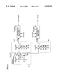
- FIG. 2 is a schematic block diagram showing a configuration of a voltage down converter 1100 shown in FIG. 1.
- FIG. 3 is a circuit diagram showing details of configurations of a VrefP generation circuit 40, a VrefS generation circuit 48 and a voltage generation circuit 44 shown in FIG. 2.
- FIG. 4 is a circuit diagram showing details of a configuration of a differential amplifier 46 shown in FIG. 2.
- FIG. 5 is a circuit diagram showing details of a configuration of a comparison circuit 102 shown in FIG. 4.
- FIG. 6 is a waveform diagram illustrating an operation of differential amplifier 46 of FIG. 4.
- FIG. 7 is a circuit diagram showing details of a configuration of a STR signal control circuit 22 shown in FIG. 1.
- FIG. 8 is a circuit diagram showing details of a configuration of an over voltage detector 142 shown in FIG. 7.
- FIG. 9 is a waveform diagram shown to describe an operation of over voltage detector 142 of FIG. 8.
- FIG. 10 is a schematic block diagram showing a configuration of a voltage down converter 1200 used in a second embodiment.
- FIG. 11 is a schematic block diagram showing a configuration of a voltage down converter 1300 used in a third embodiment.
- FIG. 12 is a schematic block diagram showing details of a configuration of a voltage down converter 2000 used in a fourth embodiment.
- FIG. 13 is a circuit diagram showing details of a configuration of a differential amplifier 1400 of FIG. 12.
- FIG. 14 is a diagram illustrating an operation of voltage down converter 2000 of FIG. 12.
- FIG. 15 is a schematic block diagram showing a configuration of a voltage down converter of a first example used in a conventional semiconductor device.
- FIG. 16 is a circuit diagram showing a configuration of a voltage down converter of a second example used in a conventional semiconductor device.
- FIG. 17 is a waveform diagram illustrating an operation of the voltage down converter of FIG. 16.
- FIG. 1 is an example of the device of the invention employed in a dynamic random access memory (DRAM).
- DRAM dynamic random access memory
- a semiconductor device 1000 includes a memory cell array 16 storing externally applied data, a row and column address buffer 6 receiving address signals Ext.A0-Ext.Ai designating an address of memory cell array 16, row decoder 10 selecting and driving one of a plurality of word lines of the memory cell array in response to a row address signal supplied from row and column address buffer 6, a column decoder 8 selecting one of a plurality of bit line pairs of memory cell array 16 in response to a column address signal supplied from row and column address buffer 6, a sense amplifier 14 amplifying a potential difference between bit line pairs of the memory cell array, an input buffer 18 receiving and amplifying externally applied input data DQ1-DQ4, an output buffer 20 externally outputting output data DQ1-DQ4 and an input-output circuit 12 connecting a bit line pair selected by the column decoder to the input buffer and the output buffer.
- Input-output circuit 12 supplies the potential of a bit line pair selected by column decoder 8 to output buffer 20.
- Output buffer 20 amplifies the supplied potential to externally output as data DQ1-DQ4.
- Input buffer 18 amplifies externally input data DQ1-DQ4.
- Input-output circuit 12 supplies data amplified at input buffer 18 to a bit line pair selected by column decoder 8.
- Row and column address buffer 6 selectively supplies externally supplied address signals Ext.A0-Ext.Ai to row decoder 10 and column decoder 8.
- Semiconductor device 1000 further includes a clock generation circuit 2 generating an operation timing for an internal circuit in response to a column address strobe signal /CAS and a row address strobe signal /RAS, a gate circuit 4 activating/inactivating the input buffer and output buffer in accordance with the value of a write control signal /W, a voltage down converter 1100 receiving external power supply potentials Ext.VccP and Ext.VccS and a ground voltage Vss and generating internal power supply potentials Int.VccP and Int.VccS, and an STR signal control circuit 22 receiving internal power supply potential Int.VccP, external power supply potential Ext.VccP and an address signal and generating a burn-in mode detection signal STR.
- a clock generation circuit 2 generating an operation timing for an internal circuit in response to a column address strobe signal /CAS and a row address strobe signal /RAS
- a gate circuit 4 activating/inactivating the input buffer
- internal power supply potential Int.VccS of the level lower than that of internal power supply potential Int.VccP is supplied to memory cell array 16, sense amplifier 14 and input-output circuit 12 in order to reduce current consumption.
- internal power supply potential Int.VccP is applied to row decoder 10, column decoder 8, input-output circuit 12, row and column address buffer 6, input buffer 18 and output buffer 20 in order to achieve a high speed operation.
- voltage down converter 1100 includes: a capacitor 32 coupling external power supply potential Ext.VccP and the ground potential; a capacitor 36 coupling internal power supply potential Int.VccP and the ground potential; a capacitor 34 coupling external power supply potential Ext.VccS and the ground potential; a capacitor 38 coupling internal power supply potential Int.VccS and the ground potential; a voltage generation circuit 44 generating a standard potential V1 in response to the internal power supply potential and the ground potential; a VrefP generation circuit 40 generating a reference potential VrefP in response to external power supply potential Ext.VccP, the ground potential and standard potential V1; a differential amplifier 42 receiving reference potential VrefP and outputting internal power supply potential Int.VccP in accordance with settings of burn-in mode detection signal STR and an activation signal ACT; a VrefS generation circuit 48 generating reference potential VrefS in response to external power supply potential Ext.VccS, the ground voltage and
- external power supply potential Ext.VccP and Ext.VccS are generally externally supplied same potential and are mutually connected in the semiconductor device.
- voltage generation circuit 44 includes an N channel transistor 68 having a source coupled with the ground potential and a gate and a drain connected together, an N channel transistor 66 having a source coupled to the ground potential and a gate receiving a potential of the drain of N channel transistor 68, a P channel transistor 62 having a source receiving external power supply potential Ext.VccP and a gate and a drain coupled with a drain of N channel transistor 66, a P channel transistor 64 having a gate receiving a potential of the drain of N channel transistor 66 and a drain connected to the drain of N channel transistor 68, and a resistor 70 coupling external power supply potential Ext.VccP and a source of P channel transistor 64.
- the potential of the drain of N channel transistor 66 is at the level of standard potential V1.
- VrefP generation circuit 40 includes a P channel transistor 72 having a gate receiving standard potential V1 and a source coupled with external power supply potential Ext.VccP and series-connected P channel transistors 74, 76 and 78 having their respective gates coupled with the ground potential and coupling a drain of P channel transistor 72 and the ground potential.
- the potential at the drain of P channel transistor 72 is at the level of reference potential VrefP.
- Differential amplifier 42 receives reference potential VrefP to generate internal power supply potential Int.VccP.
- VrefS generation circuit 48 includes a P channel transistor 80 having a gate receiving standard potential V1 and a source coupled with external power supply voltage Ext.VccS and series connected P channel transistors 82, 84 and 86 having their respective gates coupled with the ground potential and coupling a drain of P channel transistor 80 and the ground potential.
- the potential at the drain of P channel transistor 80 is at the level of reference potential VrefS.
- Differential amplifier 46 receives reference potential VrefS to generate internal power supply potential Int.VccS.
- VrefP generation circuit 40 Operations of VrefP generation circuit 40, VrefS generation circuit 48 and voltage generation circuit 44 will be described hereinafter.
- Differential amplifier 46 must generate a voltage lower than that generated by differential amplifier 42 because internal power supply potential Int.VccP is supplied to the peripheral circuitry whereas internal power supply potential Int.VccS is supplied to the memory cell array.
- the level of internal power supply potential Int.VccS generated by differential amplifier 46 is made lower than the level of internal power supply potential Int.VccP generated by differential amplifier 42 by setting the value of channel resistances of P channel transistors 82-86 lower than that of P channel transistors 74-78, thereby making reference potential VrefS lower than VrefP.
- FIG. 4 is a circuit diagram showing details of a configuration of differential amplifier 46 shown in FIG. 2.
- a configuration of differential amplifier 42 shown in FIG. 2 is the same.
- differential amplifier 46 includes a STAND-BY amplifier 92 and an ACTIVE amplifier 94.
- STAND-BY amplifier 92 includes a comparator 96 comparing internal power supply potential Int.Vcc and reference potential Vref, and a P channel transistor 98 having a gate receiving an output of comparator 96 and coupling external power supply potential Ext.Vcc and internal power supply potential Int.Vcc. Comparator 96 also receives a bias potential BiasL determining an operating current of comparator 96.
- ACTIVE amplifier 94 includes a comparator 102 comparing internal power supply potential Int.Vcc and reference potential Vref to output the result to a node ND1, a gate circuit 100 receiving activation signal ACT and burn-in mode detection signal STR, an N channel transistor 108 having a gate receiving burn-in mode detection signal STR and coupling node ND1 and the ground potential, a P channel transistor 106 having a gate receiving burn-in mode detection signal STR and a drain connected to node ND1, a P channel transistor 104 having a gate receiving activation signal ACT and coupling a source of P channel transistor 106 and the external power supply potential, and a P channel transistor 110 having a gate connected to node ND1 and coupling external power supply potential Ext.Vcc and internal power supply potential Int.Vcc.
- gate circuit 100 supplies an activation signal to comparator 102.
- burn-in detection signal STR attaining an H level causes ACTIVE amplifier 94 to supply an external power supply potential as an internal power supply potential.
- comparator 102 includes an N channel transistor 130 having a source coupled to the ground potential and a gate receiving a bias signal BIAS, an N channel transistor 128 having a gate receiving an input signal IN and a source connected to a drain of N channel transistor 130, a P channel transistor 124 having a source coupled to the external power supply potential and a gate and a drain connected to a drain of N channel transistor 128, an N channel transistor 126 having a gate receiving a reference signal REF and a source connected to the drain of N channel transistor 130, and a P channel transistor 122 having a gate receiving a potential of the drain of N channel transistor 128 and coupling external power supply potential Ext.Vcc and a drain of N channel transistor 126.
- the potential of the drain of N channel transistor 126 is an output signal OUT.
- activation signal ACT is at an L level, because the current consumption of the semiconductor device is low due to the absence of external access, for example.
- Burn-in mode detection signal STR is also at an L level because the device is at the normal operation.
- an output of gate circuit 100 is at an L level to inactivate comparator 102.
- P channel transistors 104 and 106 receive a signal of an L level at their respective gates thereby pulling up the level at node ND1 to an H level.
- a signal of an L level is also supplied to a gate of N channel transistor 108 thereby rendering N channel transistor 108 nonconductive.
- activation signal ACT attains an H level because of the external access to the semiconductor device, for example.
- gate circuit 100 pulls up the level of bias signal BIAS from an L level to an H level thereby activating comparator 102.
- activation signal ACT of an H level renders P channel transistor 104 nonconductive. Therefore, the potential at node ND1 is determined by an output of comparator 102.
- P channel transistor 110 supplies a current to a node receiving internal power supply potential Int.Vcc in accordance with the current consumption of the internal circuit, the internal power supply potential Int.Vcc is maintained.
- ACTIVE amplifier 94 is designed to have a larger current drivability and to achieve a high speed operation compared with STAND-BY amplifier 92.
- burn-in mode detection signal STR is shown to have an H level for the burn-in test.
- gate circuit 100 outputs the bias signal of an L level, thereby rendering comparator 102 inactive, P channel transistor 106 nonconductive, and N channel transistor 108 conductive.
- the potential at node ND1 is pulled down to an L level changing the state of P channel transistor 110 to be conductive thereby making the level of internal power supply potential Int.Vcc equal to that of external power supply potential Ext.Vcc.
- Activation signal ACT does not affect the operation of ACTIVE amplifier 94.
- STR signal control circuit 22 includes an over voltage detector 142 receiving address signal Ext.A1 input to a particular address pin, an NAND circuit 144 receiving an output signal SVIH of over voltage detector 142 SVIH and a test mode start signal TENT, an inverter 148 receiving a test mode end signal TEXT, an NAND circuit 146 receiving an output of NAND circuit 144, an NAND circuit 150 receiving outputs of NAND circuit 146 and of inverter 148, an inverter 152 receiving an output of NAND circuit 150, a level shift circuit 154 and an inverter 166 receiving an output of level shift circuit 154.
- NAND circuit 146 receives an output of NAND circuit 150.
- Inverter 152 outputs a signal STR0 and inverter 166 outputs burn-in mode detection signal STR.
- Level shift circuit 154 includes an N channel transistor 160 having a gate receiving signal STR0 and a source coupled to ground potential Vss, an inverter 164 receiving signal STR0, an N channel transistor 162 having a gate receiving an output of inverter 164 and a source coupled to ground potential Vss, a P channel transistor 156 having a gate receiving the potential at a drain of N channel transistor 162 and coupling a drain of N channel transistor 160 and external power supply potential Ext.VccP and a P channel transistor 158 having a gate receiving the potential at the drain of N channel transistor 160 and coupling the drain of N channel transistor 162 and external power supply potential Ext.VccP.
- over voltage detector 142 includes an input protection circuit 172 receiving address signal Ext.A1, an N channel transistor 174 having a gate and a drain receiving an output of input protection circuit 172, an N channel transistor 176 having a gate and a drain connected to a source of N channel transistor 174, a P channel transistor 178 having a gate receiving external power supply potential Ext.VccP and connecting a source of N channel transistor 176 and a node ND3, series-connected inverters 194 and 196 receiving the potential of node ND3, series-connected N channel transistors 190-192 having respective gates receiving internal power supply potential Int.VccP and coupling node ND3 and the ground potential and a reset circuit 180 resetting the potential at node ND3 to an L level.
- Reset circuit 180 includes a delay circuit 182 receiving row address strobe signal /RAS, an NAND circuit 184 receiving row address strobe signal /RAS and an output of delay circuit 182, an inverter 186 receiving an output of NAND circuit 184 and an N channel transistor 188 having a gate receiving an output of inverter 186 and coupling node ND3 and the ground potential.
- Delay circuit 182 includes a chain of inverters of an odd number for example.
- the level at node ND3 is maintained at an L level by N channel transistors 190-192 provided as resistance.
- the resistance of N channel transistors 190-192 is high in order to suppress the current consumption.
- the level of signal SVIH is hence normally maintained at an L level.
- address signal Ext.A1 falls down to an L level.
- P channel transistor 178 is turned off, and the potential at node ND3 starts falling down because of N channel transistors 190-192 having a high channel resistance.
- a pulse generated at node ND4 by the transition of row address strobe signal /RAS to an H level turns N channel transistor 188 on, thereby pulling down the potential at node ND3 to an L level.
- Burn-in test is performed during the time period t4-t5.
- test mode end signal TEXT attains an H level for an instant inverting the signal held by the latch circuit including NAND circuits 146 and 150, resulting in the transition of burn-in mode detection signal STR from an H level to an L level.
- over voltage detector 142 shown in FIG. 8 allows the detection of burn-in mode without the requirement of an additional external pin dedicated for the test, as mentioned above.
- test mode start signal TENT is generated at WCBR (/W, /CAS before /RAS) timing and test mode end signal TEXT is generated at CBR (/CAS before /RAS) timing. It is shown only as an example and various other methods of generation are conceivable.
- the response of the differential amplifier during the normal operation is not affected because the transfer gate is not inserted into the comparator output in the differential amplifier. It is advantageous because the elimination of the transfer gate saves the area. Thus an effective burn-in test can be performed realizing the reduction in current consumption and the fast operation of the semiconductor device at the same time.
- FIG. 10 is a circuit diagram showing a configuration of a voltage down converter 1200 used in place of voltage down converter 1100 in a semiconductor device according to a second embodiment.
- the semiconductor device of the second embodiment is different from the semiconductor device of the first embodiment in that the device includes a voltage down converter of which internal configuration is modified from that of voltage down converter 1100 shown in FIG. 2.
- voltage down converter 1200 is different from voltage down converter 1100 in that node supplied with external power supply potential Ext.VccP is separated from a node supplied with external power supply potential Ext.VccS, that VrefP generation circuit 40, differential amplifier 42 and voltage generation circuit 44 are powered from external power supply potential Ext.VccP, and that differential amplifier 46 and VrefS generation circuit 48 are powered from external power supply potential Ext.VccS.
- external power supply potential Ext.VccP and external power supply potential Ext.VccS are always at the same potential and are supplied to the same internal node. Therefore in the burn-in mode, internal power supply potential Int.VccS for the operation of the memory cell array and internal power supply potential Int.VccP for the operation of the peripheral circuitry are at the same level. That is, at the burn-in mode, the same power supply potential is applied to both of the memory cell array and the peripheral circuitry which should essentially operate at the different voltages.
- FIG. 11 is a circuit diagram showing a configuration of a voltage down converter 1300 used in place of voltage down converter 1200 in the semiconductor device of the third embodiment.
- the semiconductor device according to the third embodiment is different from the semiconductor device of the second embodiment in that the configuration of voltage down converter has changed from that of voltage down converter 1200 shown in FIG. 10.
- voltage down converter 1300 is different from the voltage down converter 1200 in that a node supplied with external power supply potential Ext.VccP and a node supplied with external power supply potential Ext.VccS are connected by a P channel transistor 202.
- Burn-in detection signal STR is supplied to a gate of P channel transistor 202.
- external power supply potentials Ext.VccP and Ext.VccS can be supplied respectively to the memory cell array and the peripheral circuitry. It is desirable however to connect nodes supplied with external power supply potential in the semiconductor device, in order to ensure the reliability of the semiconductor device.
- the burn-in test can be performed as in the case of semiconductor device shown in the second embodiment, while maintaining the difference between internal power supply potentials for the memory cell array and for the peripheral circuit at the time of normal operation. In addition, it is possible to independently change the test conditions for the memory cell array and for the peripheral circuitry.
- a voltage down converter 2000 is used in place of voltage down converter 1100.
- Voltage down converter 2000 is different from voltage down converter 1100 in that a differential amplifier 1400 is used in place of differential amplifier 46 generating internal power supply potential Int.VccS.
- Differential amplifier 1400 is different from differential amplifier 46 described in the first embodiment in that a source of N channel transistor 108 is coupled with internal power supply potential Int.Vcc.
- differential amplifier 1400 is the same as that of differential amplifier 46 used in semiconductor device 1000 described in the first embodiment, therefore the same elements shown in FIG. 13 are designated by the same reference characters and description will not be repeated.
- differential amplifier 42 At the time of the normal operation, that is, when burn-in mode detection signal STR attains an L level, differential amplifier 42 generates internal power supply potential Int.VccP supplied to the peripheral circuitry and differential amplifier 1400 generates internal power supply potential Int.VccS supplied to the memory cell array.
- a gate potential of driving P channel transistor 110 in differential amplifier 1400 is at the level of internal power supply potential Int.Vcc because of the conductive state of N channel transistor 108. Therefore the potential of a drain of P channel transistor 110 falls by a threshold value of P channel transistor 110 compared with the potential of a source. That is, the level of internal power supply potential Int.Vcc falls down by the threshold value of P channel transistor 110 compared with external power supply potential Ext.VccP.
- the adjustment of the voltage drop is possible by providing a plurality of transistors, which are diode connected at the time of burn-in mode and are turned to the conductive state at the normal operation, at an output of active amplifier 94.
- the potential difference is generated between internal power supply potential Int.VccS and internal power supply potential Int.VccP corresponding to the threshold value of P channel transistor 110.
- the same potential difference as at the normal operation is ensured between internal power supply potential Int.VccS and internal power supply potential Int.VccP.
Landscapes
- Engineering & Computer Science (AREA)
- Power Engineering (AREA)
- Dram (AREA)
- For Increasing The Reliability Of Semiconductor Memories (AREA)
- Static Random-Access Memory (AREA)
Abstract
Description
Claims (10)
Priority Applications (1)
| Application Number | Priority Date | Filing Date | Title |
|---|---|---|---|
| US09/503,719 US6434078B1 (en) | 1997-11-28 | 2000-02-14 | Semiconductor device allowing external setting of internal power supply voltage generated by a voltage down converter at the time of testing |
Applications Claiming Priority (2)
| Application Number | Priority Date | Filing Date | Title |
|---|---|---|---|
| JP9-328322 | 1997-11-28 | ||
| JP32832297A JP4074697B2 (en) | 1997-11-28 | 1997-11-28 | Semiconductor device |
Related Child Applications (1)
| Application Number | Title | Priority Date | Filing Date |
|---|---|---|---|
| US09/503,719 Continuation US6434078B1 (en) | 1997-11-28 | 2000-02-14 | Semiconductor device allowing external setting of internal power supply voltage generated by a voltage down converter at the time of testing |
Publications (1)
| Publication Number | Publication Date |
|---|---|
| US6038189A true US6038189A (en) | 2000-03-14 |
Family
ID=18208951
Family Applications (2)
| Application Number | Title | Priority Date | Filing Date |
|---|---|---|---|
| US09/087,868 Expired - Lifetime US6038189A (en) | 1997-11-28 | 1998-06-01 | Semiconductor device allowing external setting of internal power supply voltage generated by a voltage down converter at the time of testing |
| US09/503,719 Expired - Fee Related US6434078B1 (en) | 1997-11-28 | 2000-02-14 | Semiconductor device allowing external setting of internal power supply voltage generated by a voltage down converter at the time of testing |
Family Applications After (1)
| Application Number | Title | Priority Date | Filing Date |
|---|---|---|---|
| US09/503,719 Expired - Fee Related US6434078B1 (en) | 1997-11-28 | 2000-02-14 | Semiconductor device allowing external setting of internal power supply voltage generated by a voltage down converter at the time of testing |
Country Status (2)
| Country | Link |
|---|---|
| US (2) | US6038189A (en) |
| JP (1) | JP4074697B2 (en) |
Cited By (17)
| Publication number | Priority date | Publication date | Assignee | Title |
|---|---|---|---|---|
| US6185139B1 (en) * | 2000-01-12 | 2001-02-06 | Motorola, Inc. | Circuit and method for enabling semiconductor device burn-in |
| US6201754B1 (en) * | 1999-09-02 | 2001-03-13 | Mitsubishi Denki Kabushiki Kaisha | Semiconductor memory device having function of supplying stable power supply voltage |
| US20030020095A1 (en) * | 2001-07-25 | 2003-01-30 | Mitsubishi Denki Kabushiki Kaisha | Semiconductor integrated circuit with voltage down converter adaptable for burn-in testing |
| US6522589B1 (en) * | 2000-09-27 | 2003-02-18 | Kabushiki Kaisha Toshiba | Semiconductor apparatus and mode setting method for semiconductor apparatus |
| US6603685B2 (en) * | 2000-06-07 | 2003-08-05 | Mitsubishi Denki Kabushiki Kaisha | Semiconductor integrated circuit device capable of ensuring reliability of transistor driving high voltage |
| US20040037148A1 (en) * | 2000-08-30 | 2004-02-26 | Mitsubishi Denki Kabushiki Kaisha | MIS semiconductor device having improved gate insulating film reliability |
| US20050073356A1 (en) * | 2003-10-02 | 2005-04-07 | Myung-Gyoo Won | Voltage generation circuits for supplying an internal voltage to an internal circuit and related methods |
| US20050169087A1 (en) * | 2004-02-03 | 2005-08-04 | Renesas Technology Corp. | Semiconductor memory device capable of operating at high speed and with low power consumption while ensuring reliability of memory cell |
| US20050243644A1 (en) * | 1999-08-31 | 2005-11-03 | Renesas Technology Corp. | Semiconductor device |
| US20060055380A1 (en) * | 2004-08-04 | 2006-03-16 | Infineon Technologies Ag | Method for controlling a switching converter and control device for a switching converter |
| US20060133180A1 (en) * | 2003-08-28 | 2006-06-22 | Renesas Technology Corp. | Semiconductor memory device and semiconductor integrated circuit device |
| US20070236275A1 (en) * | 2006-04-07 | 2007-10-11 | Mellanox Technologies Ltd. | Global Reference Voltage Distribution System With Local Reference Voltages Referred to Ground And Supply |
| US20080002505A1 (en) * | 2006-06-30 | 2008-01-03 | Hynix Semiconductor Inc. | Semiconductor memory device |
| US20080112249A1 (en) * | 2006-11-14 | 2008-05-15 | Hynix Semiconductor Inc. | Circuit and method of generating voltage of semiconductor memory apparatus |
| US20080186790A1 (en) * | 2005-08-03 | 2008-08-07 | Mosaid Technologies Incorporated | Voltage down converter for high speed memory |
| US20090267684A1 (en) * | 2008-04-24 | 2009-10-29 | Hynix Semiconductor, Inc. | Internal voltage generating circuit of semiconductor device |
| US20100188140A1 (en) * | 2006-04-07 | 2010-07-29 | Mellanox Technologies Ltd. | Accurate Global Reference Voltage Distribution System With Local Reference Voltages Referred To Local Ground And Locally Supplied Voltage |
Families Citing this family (22)
| Publication number | Priority date | Publication date | Assignee | Title |
|---|---|---|---|---|
| JP4656747B2 (en) | 2001-03-30 | 2011-03-23 | ルネサスエレクトロニクス株式会社 | Semiconductor device |
| US6529436B1 (en) * | 2001-04-26 | 2003-03-04 | Lsi Logic Corporation | Supply degradation compensation for memory self time circuits |
| JP3866111B2 (en) * | 2002-01-18 | 2007-01-10 | 株式会社ルネサステクノロジ | Semiconductor integrated circuit and burn-in method |
| JP2004055009A (en) | 2002-07-18 | 2004-02-19 | Renesas Technology Corp | Semiconductor memory module |
| JP3852447B2 (en) * | 2003-06-03 | 2006-11-29 | セイコーエプソン株式会社 | Output circuit and semiconductor integrated circuit incorporating the same |
| JP4516294B2 (en) * | 2003-09-30 | 2010-08-04 | パナソニック株式会社 | Semiconductor device and manufacturing method of semiconductor device |
| JP4703133B2 (en) * | 2004-05-25 | 2011-06-15 | ルネサスエレクトロニクス株式会社 | Internal voltage generation circuit and semiconductor integrated circuit device |
| US7639531B2 (en) * | 2006-05-15 | 2009-12-29 | Apple Inc. | Dynamic cell bit resolution |
| US7511646B2 (en) | 2006-05-15 | 2009-03-31 | Apple Inc. | Use of 8-bit or higher A/D for NAND cell value |
| US7568135B2 (en) | 2006-05-15 | 2009-07-28 | Apple Inc. | Use of alternative value in cell detection |
| US7613043B2 (en) * | 2006-05-15 | 2009-11-03 | Apple Inc. | Shifting reference values to account for voltage sag |
| US8000134B2 (en) | 2006-05-15 | 2011-08-16 | Apple Inc. | Off-die charge pump that supplies multiple flash devices |
| US7852690B2 (en) * | 2006-05-15 | 2010-12-14 | Apple Inc. | Multi-chip package for a flash memory |
| US7551486B2 (en) * | 2006-05-15 | 2009-06-23 | Apple Inc. | Iterative memory cell charging based on reference cell value |
| US7911834B2 (en) * | 2006-05-15 | 2011-03-22 | Apple Inc. | Analog interface for a flash memory die |
| US7701797B2 (en) * | 2006-05-15 | 2010-04-20 | Apple Inc. | Two levels of voltage regulation supplied for logic and data programming voltage of a memory device |
| US7639542B2 (en) * | 2006-05-15 | 2009-12-29 | Apple Inc. | Maintenance operations for multi-level data storage cells |
| JP4774000B2 (en) * | 2007-03-19 | 2011-09-14 | 富士通セミコンダクター株式会社 | Semiconductor integrated circuit and semiconductor device incorporating the semiconductor integrated circuit |
| JP5040014B2 (en) * | 2007-09-26 | 2012-10-03 | ルネサスエレクトロニクス株式会社 | Semiconductor integrated circuit device |
| JP5706635B2 (en) * | 2010-06-24 | 2015-04-22 | ルネサスエレクトロニクス株式会社 | Semiconductor device and control method of internal circuit thereof |
| JP2012234601A (en) * | 2011-05-06 | 2012-11-29 | Toshiba Corp | Nonvolatile semiconductor memory |
| KR20130015942A (en) * | 2011-08-05 | 2013-02-14 | 에스케이하이닉스 주식회사 | Semiconductor memory device |
Family Cites Families (14)
| Publication number | Priority date | Publication date | Assignee | Title |
|---|---|---|---|---|
| JPH04243098A (en) * | 1991-01-16 | 1992-08-31 | Matsushita Electron Corp | Semiconductor memory device |
| JP2945508B2 (en) * | 1991-06-20 | 1999-09-06 | 三菱電機株式会社 | Semiconductor device |
| KR950008453B1 (en) | 1992-03-31 | 1995-07-31 | 삼성전자주식회사 | Internal power supply voltage generation circuit |
| JP3495787B2 (en) * | 1994-06-30 | 2004-02-09 | 株式会社ルネサステクノロジ | Semiconductor device |
| JP3705842B2 (en) * | 1994-08-04 | 2005-10-12 | 株式会社ルネサステクノロジ | Semiconductor device |
| JPH08138382A (en) | 1994-11-09 | 1996-05-31 | Nec Corp | Static memory device |
| US5762072A (en) * | 1995-05-25 | 1998-06-09 | Conlan; Robert W. | Comparator apparatus and system for activity monitors |
| KR0149577B1 (en) | 1995-06-12 | 1998-12-01 | 김광호 | Internal power supply voltage generation circuit of semiconductor memory device |
| JPH0955098A (en) * | 1995-08-15 | 1997-02-25 | Mitsubishi Electric Corp | Semiconductor memory device |
| JPH09167488A (en) * | 1995-12-18 | 1997-06-24 | Mitsubishi Electric Corp | Semiconductor memory device |
| JP3839873B2 (en) * | 1996-07-03 | 2006-11-01 | 株式会社ルネサステクノロジ | Semiconductor integrated circuit device |
| JPH10199295A (en) * | 1997-01-10 | 1998-07-31 | Fujitsu Ltd | Semiconductor integrated circuit |
| JP4046382B2 (en) * | 1997-03-27 | 2008-02-13 | 株式会社ルネサステクノロジ | Semiconductor integrated circuit device |
| JP3313081B2 (en) * | 1999-03-05 | 2002-08-12 | 三菱電機株式会社 | Semiconductor device |
-
1997
- 1997-11-28 JP JP32832297A patent/JP4074697B2/en not_active Expired - Fee Related
-
1998
- 1998-06-01 US US09/087,868 patent/US6038189A/en not_active Expired - Lifetime
-
2000
- 2000-02-14 US US09/503,719 patent/US6434078B1/en not_active Expired - Fee Related
Cited By (47)
| Publication number | Priority date | Publication date | Assignee | Title |
|---|---|---|---|---|
| US20100149883A1 (en) * | 1999-08-31 | 2010-06-17 | Renesas Technology Corp. | Semiconductor device |
| US20090046517A1 (en) * | 1999-08-31 | 2009-02-19 | Renesas Technology Corp. | Semiconductor device |
| US7693000B2 (en) | 1999-08-31 | 2010-04-06 | Renesas Technology Corp. | Semiconductor device |
| US8031546B2 (en) | 1999-08-31 | 2011-10-04 | Renesas Electronics Corporation | Semiconductor device |
| US20050243644A1 (en) * | 1999-08-31 | 2005-11-03 | Renesas Technology Corp. | Semiconductor device |
| US8264893B2 (en) | 1999-08-31 | 2012-09-11 | Renesas Electronics Corporation | Semiconductor device |
| US8482991B2 (en) | 1999-08-31 | 2013-07-09 | Renesas Electronics Corporation | Semiconductor device |
| US8644090B2 (en) | 1999-08-31 | 2014-02-04 | Renesas Electronics Corporation | Semiconductor device |
| US7453738B2 (en) * | 1999-08-31 | 2008-11-18 | Renesas Technology Corp. | Semiconductor device |
| US6337828B2 (en) | 1999-09-02 | 2002-01-08 | Mitsubishi Denki Kabushiki Kaisha | Semiconductor memory device having function of supplying stable power supply voltage |
| US6606274B2 (en) | 1999-09-02 | 2003-08-12 | Mitsubishi Denki Kabushiki Kaisha | Semiconductor memory device having function of supplying stable power supply voltage |
| US6201754B1 (en) * | 1999-09-02 | 2001-03-13 | Mitsubishi Denki Kabushiki Kaisha | Semiconductor memory device having function of supplying stable power supply voltage |
| US6185139B1 (en) * | 2000-01-12 | 2001-02-06 | Motorola, Inc. | Circuit and method for enabling semiconductor device burn-in |
| US6603685B2 (en) * | 2000-06-07 | 2003-08-05 | Mitsubishi Denki Kabushiki Kaisha | Semiconductor integrated circuit device capable of ensuring reliability of transistor driving high voltage |
| US6816418B2 (en) * | 2000-08-30 | 2004-11-09 | Renesas Technology Corp. | MIS semiconductor device having improved gate insulating film reliability |
| US20040037148A1 (en) * | 2000-08-30 | 2004-02-26 | Mitsubishi Denki Kabushiki Kaisha | MIS semiconductor device having improved gate insulating film reliability |
| US6522589B1 (en) * | 2000-09-27 | 2003-02-18 | Kabushiki Kaisha Toshiba | Semiconductor apparatus and mode setting method for semiconductor apparatus |
| US6777707B2 (en) * | 2001-07-25 | 2004-08-17 | Renesas Technology Corp. | Semiconductor integrated circuit with voltage down converter adaptable for burn-in testing |
| US20030020095A1 (en) * | 2001-07-25 | 2003-01-30 | Mitsubishi Denki Kabushiki Kaisha | Semiconductor integrated circuit with voltage down converter adaptable for burn-in testing |
| US7251182B2 (en) * | 2003-08-28 | 2007-07-31 | Renesas Technology Corp. | Semiconductor memory device and semiconductor integrated circuit device |
| US20060133180A1 (en) * | 2003-08-28 | 2006-06-22 | Renesas Technology Corp. | Semiconductor memory device and semiconductor integrated circuit device |
| US20070247952A1 (en) * | 2003-08-28 | 2007-10-25 | Noriyoshi Watanabe | Semiconductor memory device and semiconductor integrated circuit device |
| US20080247258A1 (en) * | 2003-08-28 | 2008-10-09 | Renesas Technology Corp. | Semiconductor memory device and semiconductor integrated circuit device |
| US7385870B2 (en) | 2003-08-28 | 2008-06-10 | Renesas Technology Corp. | Semiconductor memory device and semiconductor integrated circuit device |
| US7298200B2 (en) * | 2003-10-02 | 2007-11-20 | Samsung Electronics Co., Ltd. | Voltage generation circuits for supplying an internal voltage to an internal circuit and related methods |
| US20050073356A1 (en) * | 2003-10-02 | 2005-04-07 | Myung-Gyoo Won | Voltage generation circuits for supplying an internal voltage to an internal circuit and related methods |
| US20050169087A1 (en) * | 2004-02-03 | 2005-08-04 | Renesas Technology Corp. | Semiconductor memory device capable of operating at high speed and with low power consumption while ensuring reliability of memory cell |
| US7154802B2 (en) | 2004-02-03 | 2006-12-26 | Renesas Technology Corp. | Semiconductor memory device capable of operating at high speed and with low power consumption while ensuring reliability of memory cell |
| US7102953B2 (en) * | 2004-02-03 | 2006-09-05 | Renesas Technology Corp. | Semiconductor memory device capable of operating at high speed and with low power consumption while ensuring reliability of memory cell |
| US20060262629A1 (en) * | 2004-02-03 | 2006-11-23 | Renesas Technology Corp. | Semiconductor memory device capable of operating at high speed and with low power consumption while ensuring reliability of memory cell |
| US7199589B2 (en) * | 2004-08-04 | 2007-04-03 | Infineon Technologies Ag | Method for controlling a switching converter and control device for a switching converter |
| US20060055380A1 (en) * | 2004-08-04 | 2006-03-16 | Infineon Technologies Ag | Method for controlling a switching converter and control device for a switching converter |
| US7593281B2 (en) | 2005-08-03 | 2009-09-22 | Mosaid Technologies Incorporated | Voltage down converter for high speed memory |
| US8611171B2 (en) | 2005-08-03 | 2013-12-17 | Mosaid Technologies Incorporated | Voltage down converter for high speed memory |
| US20090279375A1 (en) * | 2005-08-03 | 2009-11-12 | Mosaid Technologies Incorporated | Voltage down converter for high speed memory |
| US8164968B2 (en) | 2005-08-03 | 2012-04-24 | Mosaid Technologies Incorporated | Voltage down converter for high speed memory |
| EP1913596A4 (en) * | 2005-08-03 | 2009-03-25 | Mosaid Technologies Inc | DEVOLATOR FOR HIGH SPEED MEMORY |
| US20080186790A1 (en) * | 2005-08-03 | 2008-08-07 | Mosaid Technologies Incorporated | Voltage down converter for high speed memory |
| US20100188140A1 (en) * | 2006-04-07 | 2010-07-29 | Mellanox Technologies Ltd. | Accurate Global Reference Voltage Distribution System With Local Reference Voltages Referred To Local Ground And Locally Supplied Voltage |
| US20070236275A1 (en) * | 2006-04-07 | 2007-10-11 | Mellanox Technologies Ltd. | Global Reference Voltage Distribution System With Local Reference Voltages Referred to Ground And Supply |
| US9111602B2 (en) * | 2006-04-07 | 2015-08-18 | Mellanox Technologies, Ltd. | Accurate global reference voltage distribution system with local reference voltages referred to local ground and locally supplied voltage |
| US7719907B2 (en) * | 2006-06-30 | 2010-05-18 | Hynix Semiconductor, Inc. | Test circuit for semiconductor memory device |
| US20080002505A1 (en) * | 2006-06-30 | 2008-01-03 | Hynix Semiconductor Inc. | Semiconductor memory device |
| US20080112249A1 (en) * | 2006-11-14 | 2008-05-15 | Hynix Semiconductor Inc. | Circuit and method of generating voltage of semiconductor memory apparatus |
| US7602664B2 (en) * | 2006-11-14 | 2009-10-13 | Hynix Semiconductor Inc. | Circuit and method of generating voltage of semiconductor memory apparatus |
| US7764110B2 (en) * | 2008-04-24 | 2010-07-27 | Hynix Semiconductor, Inc. | Internal voltage generating circuit of semiconductor device |
| US20090267684A1 (en) * | 2008-04-24 | 2009-10-29 | Hynix Semiconductor, Inc. | Internal voltage generating circuit of semiconductor device |
Also Published As
| Publication number | Publication date |
|---|---|
| JP4074697B2 (en) | 2008-04-09 |
| JPH11162194A (en) | 1999-06-18 |
| US6434078B1 (en) | 2002-08-13 |
| US20020021602A1 (en) | 2002-02-21 |
Similar Documents
| Publication | Publication Date | Title |
|---|---|---|
| US6038189A (en) | Semiconductor device allowing external setting of internal power supply voltage generated by a voltage down converter at the time of testing | |
| US6297624B1 (en) | Semiconductor device having an internal voltage generating circuit | |
| JP4046382B2 (en) | Semiconductor integrated circuit device | |
| US5349559A (en) | Internal voltage generating circuit | |
| US5856951A (en) | Semiconductor memory device with an improved hierarchical power supply line configuration | |
| JP2925422B2 (en) | Semiconductor integrated circuit | |
| KR0149577B1 (en) | Internal power supply voltage generation circuit of semiconductor memory device | |
| JPH11162194A5 (en) | ||
| JP3839873B2 (en) | Semiconductor integrated circuit device | |
| US5896324A (en) | Overvoltage detection circuit for generating a digital signal for a semiconductor memory device in parallel test mode | |
| US7379353B2 (en) | Voltage Pumping Device | |
| US6867641B2 (en) | Internal voltage generator for semiconductor device | |
| JPH06194424A (en) | Semiconductor apparatus | |
| US6278638B1 (en) | Pulse generator circuit and semiconductor memory provided with the same | |
| US5367491A (en) | Apparatus for automatically initiating a stress mode of a semiconductor memory device | |
| JP4073708B2 (en) | Semiconductor integrated circuit | |
| US6628162B2 (en) | Semiconductor integrated circuit | |
| US5672982A (en) | Semiconductor integrated circuit | |
| US5786716A (en) | Signal generator for generating test mode signals | |
| JP3197735B2 (en) | Power-on reset circuit and power supply voltage detection circuit | |
| JP2904276B2 (en) | Semiconductor integrated circuit device | |
| KR960000896B1 (en) | Semiconductor integrated circuit device | |
| JPH0712902A (en) | Semiconductor integrated circuit | |
| US7279955B2 (en) | Reference voltage generating circuit | |
| US20030223294A1 (en) | Integrated circuit reset circuitry |
Legal Events
| Date | Code | Title | Description |
|---|---|---|---|
| AS | Assignment |
Owner name: MITSUBISHI DENKI KABUSHIKI KAISHA, JAPAN Free format text: ASSIGNMENT OF ASSIGNORS INTEREST;ASSIGNOR:MORISHITA, FUKASHI;REEL/FRAME:009221/0303 Effective date: 19980401 |
|
| FEPP | Fee payment procedure |
Free format text: PAYOR NUMBER ASSIGNED (ORIGINAL EVENT CODE: ASPN); ENTITY STATUS OF PATENT OWNER: LARGE ENTITY |
|
| STCF | Information on status: patent grant |
Free format text: PATENTED CASE |
|
| CC | Certificate of correction | ||
| FPAY | Fee payment |
Year of fee payment: 4 |
|
| FPAY | Fee payment |
Year of fee payment: 8 |
|
| AS | Assignment |
Owner name: RENESAS ELECTRONICS CORPORATION, JAPAN Free format text: ASSIGNMENT OF ASSIGNORS INTEREST;ASSIGNOR:MITSUBISHI DENKI KABUSHIKI KAISHA;REEL/FRAME:025980/0219 Effective date: 20110307 |
|
| FPAY | Fee payment |
Year of fee payment: 12 |
|
| AS | Assignment |
Owner name: RENESAS ELECTRONICS CORPORATION, JAPAN Free format text: CHANGE OF ADDRESS;ASSIGNOR:RENESAS ELECTRONICS CORPORATION;REEL/FRAME:044928/0001 Effective date: 20150806 |