US6033400A - Shaped electrode for a resectoscope - Google Patents
Shaped electrode for a resectoscope Download PDFInfo
- Publication number
- US6033400A US6033400A US08/800,488 US80048897A US6033400A US 6033400 A US6033400 A US 6033400A US 80048897 A US80048897 A US 80048897A US 6033400 A US6033400 A US 6033400A
- Authority
- US
- United States
- Prior art keywords
- electrode
- conductive core
- shaped
- shaped conductive
- electrode member
- Prior art date
- Legal status (The legal status is an assumption and is not a legal conclusion. Google has not performed a legal analysis and makes no representation as to the accuracy of the status listed.)
- Expired - Lifetime
Links
Images
Classifications
-
- A—HUMAN NECESSITIES
- A61—MEDICAL OR VETERINARY SCIENCE; HYGIENE
- A61B—DIAGNOSIS; SURGERY; IDENTIFICATION
- A61B18/00—Surgical instruments, devices or methods for transferring non-mechanical forms of energy to or from the body
- A61B18/04—Surgical instruments, devices or methods for transferring non-mechanical forms of energy to or from the body by heating
- A61B18/12—Surgical instruments, devices or methods for transferring non-mechanical forms of energy to or from the body by heating by passing a current through the tissue to be heated, e.g. high-frequency current
- A61B18/14—Probes or electrodes therefor
- A61B18/149—Probes or electrodes therefor bow shaped or with rotatable body at cantilever end, e.g. for resectoscopes, or coagulating rollers
-
- A—HUMAN NECESSITIES
- A61—MEDICAL OR VETERINARY SCIENCE; HYGIENE
- A61B—DIAGNOSIS; SURGERY; IDENTIFICATION
- A61B17/00—Surgical instruments, devices or methods
- A61B17/32—Surgical cutting instruments
-
- A—HUMAN NECESSITIES
- A61—MEDICAL OR VETERINARY SCIENCE; HYGIENE
- A61B—DIAGNOSIS; SURGERY; IDENTIFICATION
- A61B18/00—Surgical instruments, devices or methods for transferring non-mechanical forms of energy to or from the body
- A61B2018/00053—Mechanical features of the instrument of device
- A61B2018/00059—Material properties
- A61B2018/00071—Electrical conductivity
- A61B2018/00083—Electrical conductivity low, i.e. electrically insulating
-
- A—HUMAN NECESSITIES
- A61—MEDICAL OR VETERINARY SCIENCE; HYGIENE
- A61B—DIAGNOSIS; SURGERY; IDENTIFICATION
- A61B18/00—Surgical instruments, devices or methods for transferring non-mechanical forms of energy to or from the body
- A61B2018/00571—Surgical instruments, devices or methods for transferring non-mechanical forms of energy to or from the body for achieving a particular surgical effect
- A61B2018/00601—Cutting
-
- A—HUMAN NECESSITIES
- A61—MEDICAL OR VETERINARY SCIENCE; HYGIENE
- A61B—DIAGNOSIS; SURGERY; IDENTIFICATION
- A61B18/00—Surgical instruments, devices or methods for transferring non-mechanical forms of energy to or from the body
- A61B18/04—Surgical instruments, devices or methods for transferring non-mechanical forms of energy to or from the body by heating
- A61B18/12—Surgical instruments, devices or methods for transferring non-mechanical forms of energy to or from the body by heating by passing a current through the tissue to be heated, e.g. high-frequency current
- A61B18/1206—Generators therefor
- A61B2018/1246—Generators therefor characterised by the output polarity
- A61B2018/1253—Generators therefor characterised by the output polarity monopolar
Definitions
- the invention relates generally to an electrode having a rigidly mounted electrode element adapted for use with an endoscope for tissue resection, coagulation, and ablation and more particularly relates to an electrode having a shaped conductive core electrode member having a sharp leading cutting edge for use in performing procedures, such as, for example, in the genitourinary tract on soft tissue, including bladder and prostate, for BPH procedures, for hemostasis, incision, excision and ablation or in performing other surgical procedures requiring removal or ablation of tissue.
- Resectoscopes used for transurethral resection of the prostate have four elements, a resectoscope sheath, sometimes referred to as a sheath or an outer sheath, a working element, an electrode and a telescope.
- the electrodes are operatively connected to a working element and a telescope is slideably inserted through the working element and into position along side of the electrode.
- Certain electrodes include an electrode stabilizer which is adapted to receive the telescope. The so assembled working element, telescope and electrode are removably inserted into the sheath to perform a procedure.
- the sheath with its obturator is passed through the urethra to the vicinity of the prostate and/or bladder neck.
- the obturator is then removed and the resectoscope working element with a telescope and electrode assembled thereto is inserted into the sheath.
- the electrode which is also known as a resectoscope electrode, is typically in the form of a cutting loop located at the distal end of an electrode lead member.
- An electrosurgical current which may be either a coagulation current, a cutting current or some blend thereof is applied to the cutting loop.
- the energized cutting loop is moved through the prostatic tissue and cuts the tissue being treated.
- the cutting loop can also be used to coagulate the severed vessels in the tissue.
- the peak voltage of the electrosurgical cutting currents are typically in the range of 200 volts to about 500 volts at a power level of between about 100 watts to about 300 watts.
- a resectoscope electrode having a stabilized cutting loop for a resectoscope is described in U.S. Pat. No. 4,917,082.
- the resectoscope electrode described in U.S. Pat. No. 4,917,082 is adapted for use with a urological endoscope or resectoscope.
- the electrode comprises an electrode lead, an electrode end and an electrode stabilizer.
- U.S. Pat. No. 4,917,082 discloses that the electrode may take the form of a coagulating electrode, knife electrode, retrograde knife electrode, punctate electrode or roller electrode having a smooth exterior surface.
- the Auhll Reference discussed three electrode structures, namely: (1) an electrosurgical cutting loop to treat fibroid tissues; (2) a roller ball having a smooth exterior surface for endometrial ablation (which is cauterization of the endometrium); and (3) electrosurgical needle to cut through and destroy tissue producing intrauterine synechia.
- the voltage of the electrosurgical cutting currents are typically in the range of 200 volts to about 400 volts at a power level of between 60 watts and 200 watts.
- Nd:YAG lasers for the coagulation and vaporization of prostate tissue generally referred to as abdominal tissue.
- optical fibers capable of deflecting a Nd:YAG laser energy beam about 70° to about 90° to the axis of the optical fiber (generally known as side-firing fibers) have been developed.
- the Narayan et al. Reference discusses the use of laser surgery for BPH as a promising alternative to traditional TURP.
- the Narayan et al Reference discloses that in prostate surgery tissue evaporization referred to as Transurethral Evaporization of Prostate Tissue ("TUEP") was achieved by holding the laser fiber in contact with the area to be treated.
- the TUEP was performed using an ULTRALINE Laser Fiber manufactured by Heraeus LaserSonics, Milpitas, Calif.
- the ULTRALINE Laser Fiber uses a 600 microns internal reflector fiber covered by a quartz glass cap that reflects the Nd:YAG beam at 80 degrees to the fiber axis.
- This fiber transmits a high-power density beam (spot size of 700 micron and divergence of 17 degrees, giving a power density at 60 watts to 80 watts of 16,000 to 21,000 W/cm 2 ) 1 mm from the fiber tip.
- a 23 French cystoscope (CIRCON ACMI, Stamford, Conn.) equipped with an 8 French laser bridge and a continuous flow system was used for the procedure.
- Tissue evaporation was achieved by holding the laser fiber in contact with the area to be treated, and by dragging at a rate of 1 cm/20 seconds of laser energy delivery. At the beginning of each furrow dragging was commenced one bulling was seen indicating tissue evaporation. Dragging the fiber at a rate of 1 cm/20 seconds resulted in a furrow 5 to 7 mm deep with a 3 to 4 mm rim of coagulated tissue immediately next to it.”
- T.U.D transurethral desiccation of the prostate
- T.V.P. transurethral vaporization of the prostate
- T.V.P. has the advantage that it causes little or no bleeding, fluid absorption or electrolyte imbalance. Since the residual desiccated tissue (adequate for pathologic review) is removed at the end of the procedure, there is no slough or delayed bleeding (open vessels are closed without retraction). The patient can leave the hospital, voiding (76%) within the 23 hour observation time in most instances.
- a new improved scored ball loop (A.C.M.I.) to be used with a continuous flow resectoscope has become available.
- T.V.P. is a short procedure without sphincter damage which preserves antegrade ejaculation and has a low (2-3%) subsequent procedure rate. Our experience with the last 100 consecutive patients will be detailed.”
- the first use of electrosurgical generator for prostatic resection using only an R.F. cutting current was in 1931, and the electrosurgical generator was a McCarthy Surgical Unit Type 504A sold by the Comprex Oscillator Corporation (the "McCarthy Surgical Unit”).
- the McCarthy Surgical Unit was a highly efficient vacuum tube generator producing sustained oscillation of high frequency.
- the McCarthy Surgical Unit was capable of being used for numerous procedures including prostatic resection.
- the McCarthy Surgical Unit manual states the following with respect to prostatic resection:
- the McCarthy Unit provides every modality. Every purpose which requires the use of high frequency current is served; fulguration of cysts, papillomata, tumors, etc., coagulation control of bleeding, resection and treatment.
- the current supplied by the type 504-A unit although very efficacious in resection, shows no effect on delicate insulating materials, greatly prolonging the useful life of urological instruments and electrodes.
- the selective foot switch permits hemorrhage control with the same electrode used for resection, without the necessity of changing the controls on the apparatus.”
- the McCarthy Surgical Unit manual states that the McCarthy Surgical Unit can be used for coagulation as follows:
- the unit generates by one type of current, and the controls merely provide the means for adjusting its intensity. It has been established that the same current that shows such admirable cutting characteristics is also the most effective for coagulation. By virtue of its penetrating quality the time necessary for coagulating tumor masses or malignancies has been greatly reduced. Sections of coagulated areas show a tapering off into unaffected tissue that practically eliminates the possibility of secondary hemorrhage. Tumor masses show a remarkable shrinkage during application, proportional to their fluid content.
- the technique used in coagulation with this type of current is the same as used for tissue destruction and for hemorrhage control.
- the electrode must be placed in contact with the area to be treated before the current is turned on. After treatment the current must be off before the electrode is removed. No attempt should be made to ply the area with sparks. In following this technique there is no possibility of carbonization, and no tissue can adhere to the electrode.”
- the McCarthy Surgical Unit utilized for coagulation and dissication a smooth ball shaped electrode having a 3/16 inch (4.5 mm) diameter.
- the McCarthy Surgical Unit utilized a control panel having two dials.
- the first dial was referred to as the Range Selector (R.S.) having three ranges, a low, medium and high, each representing one third of the current output.
- the second dial was referred as the Current Intensity Control (C.I.C.) and provided smooth linear adjustment over each range.
- the Range Selector was a course adjustment and the Current Intensity Control was a fine adjustment.
- the only current produced by the McCarthy Surgical Unit was a cutting current.
- the maximum current was in the order of 2,600 milliamperes.
- a plate electrode was placed under the patient and connected to an indifferent, terminal which is usually a ground terminal, to ground the patient.
- the resulting coagulation layer of the heated tissue had a thickness in the order of 0.5 mm to about 1 mm which appeared sufficient to stop bleeding.
- U.S. Patents disclose apparatus having electrosurgical electrodes: U.S. Pat. No. 5,395,363; U.S. Pat. No. 4,917,082; U.S. Pat. No. 4,765,331; U.S. Pat. No. 4,532,924; U.S. Pat. No. 4,314,559; U.S. Pat. No. 4,095,601; and U.S. Pat. No. 642,849.
- U.S. Pat. No. 5,395,363 discloses an apparatus for facilitating diathermy coagulation or ablation of tissue by the application of an electrical current to tissue.
- the apparatus is electrically connected to an electrosurgical generator and has both monopolar and bipolar embodiments.
- the apparatus includes a roller electrode, as the active electrode, having a plurality of discrete electrical discharge points.
- the plurality of discharge points is provided by diamond knurling the exterior surface of the active electrode providing a plurality of distinct points for current discharge, facilitating evenly distributed current through the tissue.
- U.S. Pat. No. 4,917,082 discloses an electrode for use with urological endoscopes.
- the electrode comprises an electrode lead, an electrode end and an electrode stabilizer.
- the active electrode is a cutting loop used to perform transurethral resection of the prostate ("TURP").
- FIG. 5E of U.S. Pat. No. 4,917,082 discloses an alternative embodiment of an electrode wherein the electrode tip 22 comprises a roller electrode having a smooth outer surface.
- U.S. Pat. No. 4,765,331 discloses an electrosurgical probe for use in treatment of tissue.
- the probe includes an active member which is generally cylindrical and has a peripheral surface on which are mounted a plurality of electrodes.
- the electrodes are mounted such that an electrode of one polarity is interposed with those of the opposite polarity.
- the length of the electrode can be chosen to obtain desired longitudinal focusing.
- U.S. Pat. No. 4,532,924 discloses a multipolar electrosurgical device and method.
- the device is in the form of an insulative probe body, which is sized to pass through a channel of the endoscope.
- the probe body is provided with electrically separate conductors which are formed of a plurality of electrodes distributed over the peripheral surface of the probe body.
- the electrically separate conductors are so sized in width W and spaced from each other by a distance S as to establish a ratio of W:S which enables effective bipolar orientation relative to tissue.
- a plurality of six electrodes are aligned longitudinally on the probe body and are used to form six bipolar electric fields.
- U.S. Pat. No. 4,614,559 discloses a conductive non-stick electrode for use with a hemostatic tissue cutting scalpel.
- the scalpel has a first layer of conductive material having a textured working surface for contacting tissue and a second coating of non-stick material deposited on the first layer at least partially filling the textured surface.
- U.S. Pat. No. 4,095,601 discloses an electrotherapeutic apparatus having a handle and roller shaped electrode for applying direct current voltage pulses for electrotherapeutic treatment.
- the roller shaped electrode has a surface that is composed of substantially pyramid shaped parts.
- the pyramids can either be arranged in rows oriented along surface lines or can be arranged in rows which are offset. In the arrangement where the rows of pyramids are offset, the tips of the pyramids are always located in the center between geometric tips of one pyramid to the tips of the neighboring pyramid in adjacent rows and the spacing is in the order of 6.955 mm.
- the pyramids do not have a geometric tip, but rather a flattened tip in the form of a square of an edge or side length amounting to 0.5 mm.
- U.S. Pat. No. 642,849 discloses an electrical passage instrument which includes smooth, current applying rollers.
- the rollers are made of carbon and are electrically separated from each other by an insulation.
- the electrode comprises an electrode lead member having an elongated conductor member having a first end and a second end with an insulative cover extended therebetween.
- the first end of the electrode member has a protruding electrode which is adapted to be electrically connected to an electrosurgical generator.
- the second end of the electrode member terminates in an active member.
- the electrode includes an electrode support member operatively connected to the loading member and includes an elongated semi-rigid bifurcated arm terminating in a conductive core spaced a predetermined distance from the active member.
- the electrode support member has a shaped conductive core electrode member having an opening extending therethrough for rigidly mounting the shaped conductive core electrode member on the conductive core.
- the shaped conductive core electrode member is in the form of an elongated curved sharp leading cutting edge which extends toward the bifurcated arm.
- a method for treating tissue comprises the steps of: (i) inserting a sheath having an obturator into a urethra; (ii) removing the obturator leaving the sheath in the urethra; (iii) inserting into a resectoscope working element a telescope and an electrode wherein the electrode has an electrode lead member which includes an elongated conductor member having a first end and a second end with an insulative cover extended therebetween wherein said first end has a protruding electrode adapted to be electrically connected to an electrosurgical generator and wherein said second end terminates in an active member and having an electrode support having an elongated semi-rigid bifurcated arm terminating in a conductive core spaced a predetermined distance from the active member and wherein the electrode support member has a shaped conductive core electrode member having an opening extending therethrough for rigidly mounting the shaped conductive core electrode member on the hub; (iv) passing the re
- the problem with the known prior art devices is that the operable power levels in terms of watts are higher than desired using a standard roller ball or a scored roller ball, the size of the craters of vaporized tissue formed in a unit of time is below the desired time verses vaporization results of tissue treatment, the time required to produce trenches of vaporized tissue is longer than desired and the thickness of remaining coagulated tissue is thinner than desired and requires additional coagulating time to develop a sufficient thick coagulate layer of tissue in the area of the treated vaporized tissue.
- the shaped conductive core electrode member of the present invention overcomes several of the problems associated with prior electrodes and devices.
- the preferred embodiment of the present invention is in the form of a shaped conductive core electrode member which has an elongated curved sharp leading cutting edge which is capable of resecting, vaporizing, and coagulating tissue. Further, tissue sections or "tissue chips" can be cut from the tissue mass and be used for pathological examination to determine if the tissue is benign or cancerous.
- the sharp leading cutting edge forms an elongated area of high current density when an R.F. electrosurgical current is applied to the shaped conductive core electrode member. This enables the shaped conductive core electrode member 52 to mechanically and electrosurgically cut tissue due to the sharp leading cutting edge.
- One advantage of the present invention is that the electrode having the shaped conductive core electrode member can be used with standard urological and gynecological resectoscopes.
- the shaped conductive core electrode member may have one or more transverse openings extending through the member to produce regions of high current density as well as to allow vaporized material to leave the operative site through the openings.
- an R.F. electrosurgical cutting current is applied to the shaped conductive core electrode member, the unique curved sharp leading cutting edge configuration causes areas of high R.F. current concentration or density which provides highly desirable deep tissue penetration. It is desirable for the electrode configuration to have large high current density areas to facilitate deep coagulation of tissue.
- Another advantage of the present invention is that the use of a leading cutting edge which maximize R.F. current concentration facilitate reduced power requirement, lower power settings on the electrosurgical generator and improved efficiency.
- zones of the electrode may be alternatively coated with an insulating media so as to concentrate the electrosurgical effect in the underlying tissue to achieve maximum hemostasis.
- the shaped conductive core electrode member may have polished or treated surface which minimizes tissue sticking or adhesion.
- the absence of tissue adhering to the surface of the sharp leading cutting edge or the sides of the shaped conductive core electrode member is desirable to maintain efficiency of vaporization as well as good vision for the surgeon.
- Another advantage of the present invention is that the structure of the shaped conductive core electrode member is less atraumatic in the non-energized mode relative to the energized mode.
- the shaped conductive core electrode member may be used in urological procedures, gynecological or other procedures requiring tissue vaporization.
- Another advantage of the present invention is that the shaped conductive core electrode member can be used with a resectoscope in performing prostatectomy for treatment of BPH of the prostate and for treating bladder tumors.
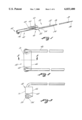
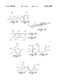
- FIG. 1 is a top, front and left side perspective view of a shaped conductive core electrode member having a blade-like leading cutting edge for use with a resectoscope;
- FIG. 2 is a top elevational view showing in greater detail the structure of the shaped conductive core electrode member having a blade-like cutting edge and bifurcated arm;
- FIG. 3 is a cross-sectional view taken along section lines 3--3 of FIG. 2;
- FIG. 4 is a cross-sectional view of another embodiment of a shaped conductive core electrode member having at least one opening extending transversely through the side walls of the shaped conductive core electrode member and with grooves formed in the side wall of the member;
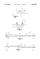
- FIG. 5 is a left elevational view of an electrode assembly having a stabilizer
- FIG. 6 is a top plan view of an electrode assembly having a shaped conductive core electrode member and an electrode stabilizer
- FIG. 7 is a front elevational view of the electrode assembly of FIG. 6;
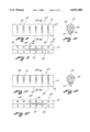
- FIG. 8 is a pictorial representation of another embodiment of a shaped conductive core electrode member having a plurality of transverse openings and a plurality of rectangular shaped ridges or grooves located on a portion of the periphery of the angular shaped end of the shaped conductive core electrode member;
- FIG. 9 is a front elevational view of the embodiment of the shaped conductive core electrode member illustrated in FIG. 8 showing the rectangular shaped grooves;
- FIG. 10 is a cross-sectional view taken along section lines 10--10 of FIG. 8 wherein the shaped conductive core electrode member has a plurality of openings and a plurality of rectangular shaped ridges or grooves located around the periphery of the angular shaped end of the shaped conductive core electrode member;
- FIG. 11 is a front elevational view of the embodiment of the shaped conductive core electrode member wherein the ridges or grooves are V-shaped;
- FIG. 12 is a front elevational view of the embodiment of the shaped conductive core electrode member illustrated in FIG. 11 wherein the ridges or grooves are V-shaped;
- FIG. 13 is a cross-sectional view taken along section lines 13--13 of FIG. 11 wherein the shaped conductive core electrode member has a plurality of openings and a plurality of "V"-shaped ridges or grooves located around the periphery of the angular shaped end of the shaped conductive core electrode member;
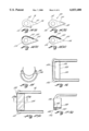
- FIGS. 14(a), 14(b), 14(c) and 14(d) are pictorial representations of steps of a process for coating a selected area of a shaped conductive core electrode member with a dielectric coating;
- FIG. 15 is a left end elevational view of an electrode assembly having a stabilizer wherein the leading edge of the shaped conductive core electrode has a plurality of sharp teeth members extending toward the bifurcated arm;
- FIG. 16 is a top plan view of the distal end of the electrode assembly showing the shaped conductive core electrode illustrated in FIG. 15;
- FIG. 17(a) is a top plan view of the distal end of another embodiment of an electrode assembly wherein the shaped conductive core electrode has a substantially planar top surface which is coated with a dielectric coating;
- FIG. 17(b) is a cross-section view taken along section lines 17(b)--17(b) of FIG. 17(a) showing the substantially planar top surface and the laminated dielectric coating formed on the surface of the substantially planar top surface;
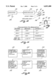
- FIG. 18 is a schematic diagram of a resectoscope system using a shaped conductive core electrode member of the present invention for treatment of patient tissue;
- FIG. 19 is a chart showing parameters for vaporization
- FIG. 20 is a block diagram of a method for using the shaped conductive core electrode member of the present invention in a urological procedure
- FIG. 21 is a diagrammatic representation of a trough formed in a patient tissue using a shaped conductive core electrode member of the preferred embodiment of this invention.
- FIG. 22 is a front elevational view of a shaped conductive core electrode member wherein the shaped trailing edge is in the form of a plurality of sharp edges for forming a plurality of areas of high current density when an R.F. electrosurgical current is applied thereto and which extend away from the bifurcated to form a trailing edge for the shaped conductive core electrode member;
- FIG. 23 is a sectional view taken along section lines 23--23 of FIG. 22;
- FIG. 24 is a front, left end and top perspective view of an electrode of FIG. 22 having the plurality of sharp teeth extending away from the bifurcated arm;
- FIG. 25 is a top plan view of the shaped conductive core electrode member prior to forming the electrode and rigidly affixing the same to the bifurcated arms as illustrated in FIG. 22 showing a pair of spaced opposed conducting support leads operatively connected to the shaped conductive core electrode member wherein the width of the shaped conductive core electrode member is greater than the width of the spaced opposed conducting support leads;
- FIG. 26 is a front plan view of the shaped conductive core electrode member illustrated in FIG. 25 showing that the thickness of the spaced opposed conducting support leads is substantially equal to the thickness of the shaped conductive core electrode member;
- FIG. 27 is a front, left end and top perspective view of another embodiment of an electrode having the plurality of sharp teeth extending towards the bifurcated arm;
- FIG. 28 is a left end elevational view of the embodiment of the shaped conductive core electrode member of FIG. 27 wherein the shaped leading edge thereof is in the form of a plurality of sharp edges for forming a plurality of areas of high current density when an R.F. electrosurgical current is applied thereto and which extends towards the bifurcated arm and to form a shaped leading edge for the shaped conductive core electrode member;
- FIG. 29 is a front plan view of the embodiment of FIG. 28;
- FIG. 30 is a front plan view of another embodiment of a shaped conductive core electrode member showing that the thickness of the shaped conductive core electrode member is greater than the thickness of the pair of the spaced opposed conducting support leads;
- FIG. 31 is a section view taken along section lines 31--31 of FIG. 30.
- the shaped conductive core electrode member electrode is shown generally as 20.
- the preferred embodiment has a sharpened blade-like leading cutting edge 66.
- the structure of the electrode is for use with a resectoscope.
- the electrode 20 includes an electrode lead member 22 having an elongated conductor member 26 having a first end 30 and a second end 32.
- An insulative cover 34 extends between the first end 30 and the second end 32.
- the first end 30 has a protruding electrode 38 which is adapted to be electrically connected to an electrosurgical generator.
- the second end 32 terminates in an active member or a loading member shown generally as 40.
- the active member 40 has an electrode support member, shown generally as 42, operatively connected to the loading member 40.
- the electrode support member 42 has an elongated semi-rigid bifurcated arm 46 which terminates in a conductive core 50 (illustrated in FIG. 3) spaced at a predetermined distance from the active member 40.
- the bifurcated arm 46 has an insulative covering formed thereon except in the portion thereof which forms the conductive core 50.
- the electrode support member 42 has a shaped conductive core electrode member shown generally 52 having an opening 54 (shown in FIGS. 3 and 4) extending therethrough for rigidly mounting the shaped conductive core electrode member 52 on the conductive core 50.
- the electrode stabilizer 60 for stabilizing the shaped conductive core electrode member 52 is proximate a distal region of a telescope mounted in a resectoscope working element. It is envisioned that the electrode 20 does not need to have the electrode stabilizer 60 in order to practice this invention.
- the distal end of a telescope shown by dashed line 62 is removably supported by stabilizer 60.
- the stabilizer 60 has a pair of support arms 64 which define a hollowed out space 68 to receive a telescope.
- FIGS. 2 and 3 depict the structure of the preferred embodiment of the shaped conductive core electrode member 52 in the form of a sharp leading cutting edge 66.
- the shaped conductive core electrode member 52 includes a side wall portion 72 and an opposed blunt shaped surface 70.
- the conductive core 50 extends through the central opening 54 located in the shaped conductive core electrode member 52.
- the bifurcated arm 46 extends toward the protruding electrode 38.
- FIG. 4 shows in greater detail the structure of the shaped conductive core electrode member 52 wherein at least one opening 76 is formed cutting through the side wall portion 72.
- the blunt shaped end 70 is smooth.
- another embodiment utilizes grooves formed in the side wall portion 72, or wherein the grooves extend around the blunt shaped end 70.
- FIG. 5 depicts in the left side elevational view the structure details of the electrode assemblies showing the electrode stabilizer 60, and the relationship thereof to the bifurcated arm 46 and the shaped conductive core electrode member 52.
- FIGS. 6 and 7 show the entire electrode assembly 20 and shows that the orientation of the sharp leading cutting edge 66 of the shaped conductive core electrode member 52 extends toward the bifurcated arm 46.
- the plane of the sharp leading cutting edge 66 is positioned substantially perpendicular to the direction of cutting.
- the sharp leading cutting edge 66 could be positioned at a slight angular bias of ⁇ 20° to this perpendicular position.
- FIGS. 8, 9 and 10 depict another embodiment of a shaped conductive core electrode member for practicing this invention.
- the shaped conductive core electrode member 52 is illustrated to include the plurality of holes 76 through side walls portion 72 located between the cutting edge 66 and blunt shaped end 70. It is envisioned that the orientation of the openings could be at different selected angles, such as for example perpendicular to one of the side walls 72.
- the embodiment illustrated in FIGS. 8, 9 and 10 include a plurality of substantially parallel spaced rectangular shaped ridges or grooves 90 which are located in the side wall portion 72 as illustrated in FIGS. 8, 9 and 10, the ridges or grooves 90 do not extend around the blunt shaped end 70.
- the ridges or grooves 90 have sharp edges illustrated as 94 which function as areas of higher current densities for R.F. electrosurgical current applied to the electrode 20. Specifically, electrosurgical current densities are larger at the sharp edges 94 which enable the shaped conductive core electrode member 52 to effectively coagulate tissue and reduce bleeding during the procedure. Note that FIGS. 8 and 9 show the electrode 52 in its straight form prior to being formed into its final arc-shaped form.
- the typical depth of the ridges or grooves 90 would be in the order of 0.008 inches (0.20 mm) to about 0.015 inches (0.38 mm) and the width of the ridges or grooves would be in order of about of 0.010 inches (0.25 mm) with a spacing between grooves in order of about 0.010 inches (0.25 mm) making the pitch thereof to be approximately thereof 0.020 inches (0.5 mm).
- the width of the shaped conductive core electrode member 52 as measured from the sharp leading cutting edge 66 to the blunt shaped end 70 would be in the order of about 0.075 inches (2 mm).
- the opening 76 would have a diameter in the order of 0.016 inches (0.4 mm).
- FIGS. 11, 12 and 13 depict another embodiment of a shaped conductive core electrode member 52 wherein ridges or grooves 100 extend from the side wall portion 72 and around the circumference or outside surface of the blunt shaped member 70.
- the ridges or grooves 100 are V-shaped as illustrated by edge 102, however they could also be square shaped or radius shaped.
- the "V"-shaped ridges or grooves 100 have sharp edges 94 to develop increased current densities in the same manner as di scussed above with respect to FIGS. 8, 9 and 10.
- FIGS. 14(a), 14(b), 14(c) and 14(d) illustrate the steps of a method for forming a dielectric coating on a selected surface of a shaped conductive core electrode member 110.
- the shaped conductive core electrode member 110 has a top surface 112 and a bottom surface 114.
- the shaped conductive core electrode member 110 has, in this embodiment, a sharp leading cutting edge 116.
- the openings 76 and plurality of substantially parallel spaced rectangular shaped ridges or grooves 90 have been fabricated or formed into the shaped conductive core electrode member 110.
- this step is done before the application of the dielectric material and is referred to by the step of forming the openings 76 and plurality of substantially parallel spaced rectangular shaped ridges or grooves 90 into the shaped conductive core electrode member 110.
- the next step is the step of forming a mask or resist layer of material, depicted by mask 118, over the surface areas of the shaped conductive core electrode member 110.
- the surface areas which are masked are those surface areas not to have the dielectric material affixed thereto.
- the surface areas of the shaped conductive core electrode member 110 which are not to have the dielectric material affixed thereto are the sides and bottom surface of the shaped conductive core electrode member 110.
- a selected section or area of the top section shown generally by arrow 120, is left exposed or unmasked or uncoated with the resist layer of material.
- the next step is the step of affixing onto the exposed top section 120 of the shaped conductive core electrode member 110 a dielectric material having a predetermined thickness.
- the step of affixing may be accomplished by many techniques known in the art such as, for example, sputtering, vapor deposition, chemical formation or use of other known material depositing techniques.
- the layer of dielectric material is depicted by the cross-sectional insulating layer 122.
- the thickness of the dielectric material should be in the range of about 5 microns to about 50 microns.
- the preferred thickness of the dielectric layer is about 25 microns.
- the ultimate thickness of the dielectric layer 122 may be obtained by either a single layer of the desired thickness or a plurality of thin layers which, in the aggregate, is substantially equal to the thickness of the dielectric layer 122.
- the next step is the step of removing the mask or resist layer of material depicted by mask 118. This re-exposes the surface areas of the shaped conductive core electrode member 110 which are not to have the dielectric material affixed thereto. In this embodiment, the sides and bottom surface of the shaped conductive core electrode member 110 are re-exposed. This leaves the dielectric material 122 located on and affixed to the selected section or area of the top section 120.
- FIGS. 15 and 16 illustrate another embodiment of a shaped conductive core electrode member 124 having a plurality of rectangular shaped grooves 126 formed in the bottom portion of a shaped conductive core electrode member 124.
- the shaped conductive core electrode member 124 has a cross-section in the form of a two generally arcuate shaped, sloped intersecting surfaces forming a knife-like leading cutting edge 126 positioned toward the bifurcated arm 46 as illustrated in FIG. 2. the other Generally, the cross-sectional area defined in FIG. 3 is representative of the cross-sectional area of FIG. 16.
- the knife-like leading cutting edge 126 includes a saw tooth cutting edge having a plurality of individual cutting teeth 128. Each individual cutting tooth 128 has a sharp or pointed end 130 which causes high current density when an electrosurgical current is applied to the shaped conductive core electrode member 124.
- FIGS. 17(a) and 17(b) illustrate yet another embodiment of a shaped conductive core electrode member 134 which may or may not have a plurality of rectangular shaped ridges or grooves.
- the ridges or grooves may be similar to rectangular shaped grooves 126 shown in FIG. 15, formed in the bottom portion of a shaped conductive core electrode member 134.
- the ridges or grooves may be similar to the "V"-shaped ridges or grooves 102 illustrated in FIG. 12.
- the shaped conductive core electrode member 124 has a cross-sectional area forming a rounded angular shaped trailing edge 134 and a substantially planer top or lateral surface 138.
- the substantially planer surface 138 terminates in the knife-like leading cutting edge 138.
- the knife-like leading cutting edge 138 is formed by two sloped intersecting surfaces.
- the knife-like leading cutting edge 138 is positioned toward the bifurcated arm 46 as illustrated in FIG. 2.
- the cross-sectional area of the electrode 140 is supported by the core 142 which forms part of the bifurcated arm 46. Also, the substantially planer surface 136 is coated with a thin dielectric coating 138. The thin dielectric coating 144 functions to prevent tissue or other material from sticking to or becoming affixed to the shaped electrode 140.
- the knife-like leading cutting edge 138 may include a saw tooth cutting edge similar to the saw tooth cutting edge illustrated in FIG. 16 having a plurality of individual cutting teeth 128.
- FIG. 18 is a schematic diagram of an electrosurgical generator 190 which is operatively connected to a resectoscope 194.
- the electrosurgical generator 190 produces typical R.F. electrosurgical currents which may be a cutting current, a blend current or a coagulating current.
- typical R.F. electrosurgical currents is set forth at pages 96 through 97 and page 100 of the ValleyLab SSE4 Instruction Manual.
- the electrosurgical current from the generator 190 is applied by the electrode tip 22 to the shaped conductive core electrode member 48 to a patient tissue to be treated, shown by tissue 198.
- the dispersive electrode 202 is electrically connected to an isolated terminal 206.
- the electrosurgical generator 190 is electrically connected to the isolated terminal 206.
- the shaped conductive core electrode member 48 has areas of high concentration of R.F. electrosurgical current which form on the knife-like leading cutting edge, such as for example leading cutting edge 66 illustrated in FIG. 2, and on the protruding ridges or grooves, such as, for example, sharp edges 94 on the rectangular shaped grooves illustrated in FIG. 9 or the sharp edges 94 on the "V"-shaped grooves illustrated in FIG. 12.
- the sharp points and/or knife-like leading cutting edge of the shaped conductive core electrode member 48 result in areas of increased current density which electrically interact with the tissue being treated.
- the shaped conductive core electrode member 48 is moved slowly through the tissue allowing the shaped conductive core electrode member 48 to electrosurgically cut the tissue, not unlike moving a hot knife through butter, thereby cutting away an elongated chip of tissue and coagulating the remaining tissue forming a trough therein.
- the chips of tissue can be used for a pathological analysis to determine the status of the tissue, such as for example, whether the tissue is benign or cancerous.
- the shaped conductive core electrode member 48 functions as an active electrode while the patient grounding plate functions as a dispersive electrode.
- FIG. 19 shows a table of parameters for vaporization using the teachings of the invention.
- the procedure can be performed with the shaped conductive core electrode member 48 in either air or liquid as a medium.
- air requires less electrical voltage and power such that an electrosurgical voltage of about 200 volts and a power level of between 160 watts to 240 watts will provide the desired cutting action.
- An electrosurgical voltage of about 300 volts in air produces charring resulting in a tissue layer having high resistance, which is undesirable.
- an electrosurgical voltage of about 300 volts or higher and a power level of between 160 and 300 watts produces the desired cutting action while an electrosurgical voltage of about 400 volts to about 500 when cutting volts produces charring of the tissue, which is undesirable.
- FIG. 20 illustrates the steps of the method.
- the method comprises the steps of inserting a sheath, which may be an outer sheath for a continuous flow resectoscope (CFR), having a visual obturator into a urethra as shown by step 210.
- CFR continuous flow resectoscope
- Step 214 provides for inserting into a resectoscope working element a telescope and an electrode wherein the electrode has an electrode lead member which includes an elongated conductor member having a first end and a second end with an insulative cover extended therebetween wherein said first end has a protruding electrode adapted to be electrically connected to an electrosurgical generator and wherein said second end terminates in an active member and having an electrode support having an elongated semi-rigid bifurcated arm terminating in a conductive core spaced a predetermined distance from the active member and wherein the electrode support member has a shaped conductive core electrode member having an opening extending therethrough for rigidly mounting the shaped conductive core electrode member on the conductive core.
- Steps 214 and 216 provide for assembling the resectoscope working element having the telescope and electrode mounted thereon into an inner sheath and then inserting this assembly into the outer sheath and visually positioning the shaped conductive core electrode member in the proximity of the tissue to be treated.
- Step 218 provides for irrigating the tissue to be treated with an irrigation fluid.
- Step 220 provides for applying an electrosurgical cutting current to the shaped conductive core electrode member at a selected voltage level of between about 200 volts to about 500 volts.
- Step 220 also provides for moving the shaped conductive core electrode member having an electrosurgical cutting current applied thereto through the tissue to be treated to resect and coagulate the tissue.
- the method for treating prostate tissue comprises the step of irrigating through an instrument the prostate tissue to be treated and applying a high electrosurgical cutting current to shaped conductive core electrode member at a selected voltage level of between about 200 volts to about 500 volts, and moving the shaped conductive core electrode member having the electrosurgical cutting current applied thereto through a selected portion of prostate tissue to be treated to resect and coagulate the tissue and form a trough having a coagulation layer of treated tissue preferably of at least 2 mm.
- FIG. 21 is a pictorial representation of a tissue area shown by 230, such as a prostate, wherein the shaped conductive core electrode member 52 supported by bifurcated arm 46 has formed a crater or trough 234 having side walls 232.
- the velocity of movement of the shaped conductive core electrode member 52 in prostate tissue is approximately 5 mm/sec.
- the depth of the trough (height of side walls 232) is in the order of about 3 mm.
- FIG. 22 is a front elevational view of FIG. 24, an electrode shown generally by arrow 240 has a pair of opposed conducting support leads 246, shown in FIG. 23, and a shaped conductive core electrode member 248.
- the shaped conductive core member 248 defines a shaped trailing edge, shown as 250 in FIG. 23, which is in the form of a plurality of sharp edges 252 for forming a plurality of areas of high current density when an R.F. electrosurgical current is applied thereto.
- the shaped trailing edge in the form of the plurality of sharp edges 252 extend away from the bifurcated arm to form a trailing edge for the shaped conductive core electrode member 248.
- FIG. 23 shows that the pair of spaced opposed conducting support leads 246 are deflected or bent in a direction to cause the plurality of sharp edges 252 to extend away from the bifurcated to form a trailing edge for the shaped conductive core electrode member 248.
- the electrode 240 is usually used to resect or cut tissue as the electrode 240 is transported by the resectoscope towards the bifurcated arm 46.
- the shaped leading edge 250 forms the trailing edge of electrode 240 as illustrated in FIG. 27.
- FIGS. 25 and 26 the top plan view of the shaped conductive core electrode member 248 is shown prior to forming the electrode and rigidly affixing the same to the bifurcated arms as illustrated in FIG. 22.
- the shaped conductive core electrode member 248 has a pair of spaced opposed conducting support leads 246 operatively connected to the shaped conductive core electrode member 248 wherein the width of the shaped conductive core electrode member 248 is greater than the width of the spaced opposed conducting support leads 246.
- FIG. 26 the front plan view of the shaped conductive core electrode member 248 illustrated in FIG. 25 and shows that the thickness of the spaced opposed conducting support leads 246 is substantially equal to the thickness of the shaped conductive core electrode member 248.
- FIGS. 27, 28 and 29 another embodiment of an electrode 256 having a pair of spaced opposing conducting support leads 258 and a shaped conductive core electrode member 260.
- the shaped conductive core electrode member 260 has a plurality of sharp teeth 264 extending towards the bifurcated arm 46 (illustrated in FIG. 1).
- the shaped leading edge includes the plurality of sharp edges 264 for forming a plurality of areas of high current density when an R.F. electrosurgical current is applied thereto.
- FIGS. 30 and 31 show another embodiment of an electrode 270 having a pair of spaced opposed conducting support leads 274 and a shaped conductive core electrode member 276.
- the shaped conductive core electrode member 274 has a plurality of sharp teeth 278 extending towards the bifurcated arm 46 (illustrated in FIG. 1).
- FIG. 29 shows that the thickness of the shaped conductive core electrode member 276 is greater than the thickness of the pair of the spaced opposed conducting support leads 274.
- the shaped leading edge is in the form of an elongated, substantially sharp cutting leading edge or the leading edge is in the form of a plurality of sharp edges
- application of an R.F. electrosurgical current to the electrode results in areas of high current density.
- the electrosurgical voltage is programmed at a selected voltage level of between about 200 volts to about 500 volts, contacting and moving the vaporizing, cutting and coagulating shaped conductive core electrode member through a selected portion of the tissue to be treated results in the resection and the vaporization of the tissue while forming a coagulation layer in a remaining crater of the treated tissue.
- the R.F. electrosurgical setting cooperates with the raised ridges, protrusions, sharp edges or points to form areas of increased current densities which generate sufficient current flow at the appropriate voltage levels to vaporize and coagulate the tissue.
- the tissue surrounding the vaporized tissue becomes coagulated by the R.F. electrosurgical current at the boundary of the vaporized tissue resulting in a layer of necrosed tissue around the side walls 194 and trough 234 as illustrated in FIG. 21.
- the thickness of the coagulated layer is in the order of about 1.5 mm to about 2 mm.
- Energy settings in the range of 160 watts to about 300 watts is desired, with the preferred power settings to be at least 250 watts.
- the electrode structure could be designed for use in a gynecological procedure with a gynecological resectoscope for performing removal of tissue or debulking myomas.
- the shaped conductive core electrode member could be used as part of instrumentation for use in general surgery and minimally invasive surgery.
Landscapes
- Health & Medical Sciences (AREA)
- Surgery (AREA)
- Engineering & Computer Science (AREA)
- Life Sciences & Earth Sciences (AREA)
- Biomedical Technology (AREA)
- Otolaryngology (AREA)
- Nuclear Medicine, Radiotherapy & Molecular Imaging (AREA)
- Plasma & Fusion (AREA)
- Physics & Mathematics (AREA)
- Heart & Thoracic Surgery (AREA)
- Medical Informatics (AREA)
- Molecular Biology (AREA)
- Animal Behavior & Ethology (AREA)
- General Health & Medical Sciences (AREA)
- Public Health (AREA)
- Veterinary Medicine (AREA)
- Surgical Instruments (AREA)
Abstract
Description
Claims (25)
Priority Applications (1)
| Application Number | Priority Date | Filing Date | Title |
|---|---|---|---|
| US08/800,488 US6033400A (en) | 1996-04-19 | 1997-02-14 | Shaped electrode for a resectoscope |
Applications Claiming Priority (2)
| Application Number | Priority Date | Filing Date | Title |
|---|---|---|---|
| US1566896P | 1996-04-19 | 1996-04-19 | |
| US08/800,488 US6033400A (en) | 1996-04-19 | 1997-02-14 | Shaped electrode for a resectoscope |
Publications (1)
| Publication Number | Publication Date |
|---|---|
| US6033400A true US6033400A (en) | 2000-03-07 |
Family
ID=26687671
Family Applications (1)
| Application Number | Title | Priority Date | Filing Date |
|---|---|---|---|
| US08/800,488 Expired - Lifetime US6033400A (en) | 1996-04-19 | 1997-02-14 | Shaped electrode for a resectoscope |
Country Status (1)
| Country | Link |
|---|---|
| US (1) | US6033400A (en) |
Cited By (25)
| Publication number | Priority date | Publication date | Assignee | Title |
|---|---|---|---|---|
| US6245069B1 (en) * | 1995-12-22 | 2001-06-12 | Karl Storz Gmbh & Co. Kg | Cutting loop electrode for high-frequency instrument |
| US6494881B1 (en) | 1997-09-30 | 2002-12-17 | Scimed Life Systems, Inc. | Apparatus and method for electrode-surgical tissue removal having a selectively insulated electrode |
| US20030130649A1 (en) * | 2000-12-15 | 2003-07-10 | Murray Steven C. | Method and system for treatment of benign prostatic hypertrophy (BPH) |
| US20030149442A1 (en) * | 2002-02-04 | 2003-08-07 | Gellman Barry N. | Resistance heated tissue morcellation |
| US20040260280A1 (en) * | 2003-05-01 | 2004-12-23 | Sartor Joe Don | Suction coagulator with dissecting probe |
| US20050177145A1 (en) * | 2002-02-22 | 2005-08-11 | Laserscope | Method and system for photoselective vaporization for gynecological treatments |
| US20060084959A1 (en) * | 2000-12-15 | 2006-04-20 | Laserscope | Method and system for photoselective vaporization of the prostate, and other tissue |
| US7206641B2 (en) | 2003-07-23 | 2007-04-17 | University Hospitals Of Cleveland | Mapping probe system for neuromuscular electrical stimulation apparatus |
| US20080077129A1 (en) * | 2006-09-27 | 2008-03-27 | Van Wyk Robert A | Electrosurgical Device Having Floating Potential Electrode and Adapted for Use With a Resectoscope |
| US20080091186A1 (en) * | 2006-10-13 | 2008-04-17 | Tyco Electronics Corporation | Electro-surgical device RF energy needle electrical shorting plate |
| US20080208189A1 (en) * | 2007-02-21 | 2008-08-28 | Van Wyk Robert A | Instruments and Methods for Thermal Tissue Treatment |
| US20080287940A1 (en) * | 2007-05-14 | 2008-11-20 | Hunter Lowell D | Fiber Pole Tip |
| US20080287934A1 (en) * | 2007-05-15 | 2008-11-20 | Hunter Lowell D | Laser Handle and Fiber Guard |
| US20090264878A1 (en) * | 2008-04-21 | 2009-10-22 | Electro Medical Associates, Llc | Devices and methods for ablating and removing a tissue mass |
| US20100016854A1 (en) * | 2003-08-11 | 2010-01-21 | Electromedical Associates Llc | Bipolar electrosurgical device with floating-potential electrodes |
| US20110028970A1 (en) * | 1995-11-22 | 2011-02-03 | Jean Woloszko | Electrosurgical systems and methods for removing and modifying tissue |
| WO2012175912A1 (en) * | 2011-06-23 | 2012-12-27 | Gyrus Medical Limited | Electrosurgical electrode |
| US20140088592A1 (en) * | 2012-08-10 | 2014-03-27 | Robert A. Van Wyk | Plasma resection electrode |
| US8992521B2 (en) | 2010-04-22 | 2015-03-31 | Electromedical Associates, Llc | Flexible electrosurgical ablation and aspiration electrode with beveled active surface |
| US9011426B2 (en) | 2010-04-22 | 2015-04-21 | Electromedical Associates, Llc | Flexible electrosurgical ablation and aspiration electrode with beveled active surface |
| US9168084B2 (en) | 2010-05-11 | 2015-10-27 | Electromedical Associates, Llc | Brazed electrosurgical device |
| US20170100190A1 (en) * | 2015-10-12 | 2017-04-13 | Mysore Wifiltronics PVT LTD | High performance material for electro-surgical vaporization electrodes |
| US9643255B2 (en) | 2010-04-22 | 2017-05-09 | Electromedical Associates, Llc | Flexible electrosurgical ablation and aspiration electrode with beveled active surface |
| WO2017076721A1 (en) * | 2015-11-03 | 2017-05-11 | Olympus Winter & Ibe Gmbh | High-frequency tool for medical resectoscopes |
| US20250032188A1 (en) * | 2021-12-20 | 2025-01-30 | University Of Florida Research Foundation, Incorporated | Method, apparatus, and system for removal of lesions |
Citations (13)
| Publication number | Priority date | Publication date | Assignee | Title |
|---|---|---|---|---|
| SU253911A1 (en) * | М. И. Абрамович, Б. Д. Курносое А. А. Сакювич | A DEVICE FOR THE REGULATION OF THE EXCITATION AND EXTENSION OF THE FIELD OF SYNCHRONOUS ASCHIN | ||
| US642849A (en) * | 1899-11-27 | 1900-02-06 | Whitall Tatum & Co | Electrical massage instrument. |
| US3835842A (en) * | 1972-07-03 | 1974-09-17 | J Iglesias | Endoscope with continuous irrigation |
| US4095601A (en) * | 1975-06-09 | 1978-06-20 | Aufranc Charles Walte | Electrotherapeutic apparatus |
| US4314559A (en) * | 1979-12-12 | 1982-02-09 | Corning Glass Works | Nonstick conductive coating |
| US4532924A (en) * | 1980-05-13 | 1985-08-06 | American Hospital Supply Corporation | Multipolar electrosurgical device and method |
| US4765331A (en) * | 1987-02-10 | 1988-08-23 | Circon Corporation | Electrosurgical device with treatment arc of less than 360 degrees |
| US4917082A (en) * | 1988-06-02 | 1990-04-17 | Circon Corporation | Resectoscope electrode |
| US5354296A (en) * | 1993-03-24 | 1994-10-11 | Symbiosis Corporation | Electrocautery probe with variable morphology electrode |
| US5395363A (en) * | 1993-06-29 | 1995-03-07 | Utah Medical Products | Diathermy coagulation and ablation apparatus and method |
| US5569244A (en) * | 1995-04-20 | 1996-10-29 | Symbiosis Corporation | Loop electrodes for electrocautery probes for use with a resectoscope |
| US5582610A (en) * | 1994-09-30 | 1996-12-10 | Circon Corporation | Grooved slider electrode for a resectoscope |
| US5782829A (en) * | 1995-12-06 | 1998-07-21 | Northgate Technologies Incorporated | Resectoscope electrode assembly and methods of use |
-
1997
- 1997-02-14 US US08/800,488 patent/US6033400A/en not_active Expired - Lifetime
Patent Citations (13)
| Publication number | Priority date | Publication date | Assignee | Title |
|---|---|---|---|---|
| SU253911A1 (en) * | М. И. Абрамович, Б. Д. Курносое А. А. Сакювич | A DEVICE FOR THE REGULATION OF THE EXCITATION AND EXTENSION OF THE FIELD OF SYNCHRONOUS ASCHIN | ||
| US642849A (en) * | 1899-11-27 | 1900-02-06 | Whitall Tatum & Co | Electrical massage instrument. |
| US3835842A (en) * | 1972-07-03 | 1974-09-17 | J Iglesias | Endoscope with continuous irrigation |
| US4095601A (en) * | 1975-06-09 | 1978-06-20 | Aufranc Charles Walte | Electrotherapeutic apparatus |
| US4314559A (en) * | 1979-12-12 | 1982-02-09 | Corning Glass Works | Nonstick conductive coating |
| US4532924A (en) * | 1980-05-13 | 1985-08-06 | American Hospital Supply Corporation | Multipolar electrosurgical device and method |
| US4765331A (en) * | 1987-02-10 | 1988-08-23 | Circon Corporation | Electrosurgical device with treatment arc of less than 360 degrees |
| US4917082A (en) * | 1988-06-02 | 1990-04-17 | Circon Corporation | Resectoscope electrode |
| US5354296A (en) * | 1993-03-24 | 1994-10-11 | Symbiosis Corporation | Electrocautery probe with variable morphology electrode |
| US5395363A (en) * | 1993-06-29 | 1995-03-07 | Utah Medical Products | Diathermy coagulation and ablation apparatus and method |
| US5582610A (en) * | 1994-09-30 | 1996-12-10 | Circon Corporation | Grooved slider electrode for a resectoscope |
| US5569244A (en) * | 1995-04-20 | 1996-10-29 | Symbiosis Corporation | Loop electrodes for electrocautery probes for use with a resectoscope |
| US5782829A (en) * | 1995-12-06 | 1998-07-21 | Northgate Technologies Incorporated | Resectoscope electrode assembly and methods of use |
Non-Patent Citations (6)
| Title |
|---|
| Operating Manual, McCarthy Surgical Unit Type 504A, Comprex Oscillator Corporation. * |
| Transurethral Evaporization of Prostrate (Turp) With Nd:Yag Laser Using Contact Free Beam Technique: Results in 61 Patients with Benign Prostatic Hyperplasia by Peby Perinchery Narayan, M.D., George Fournier, M.D., R. Indudhara, M.D., R. Leidich, M.D., K. Shinohara, M.D. and Alex Ingermann, M.D. pp. 813 820, Jun., 1994, vol. 43, No. 6, Issue of Urology. * |
| Transurethral Evaporization of Prostrate (Turp) With Nd:Yag Laser Using Contact Free Beam Technique: Results in 61 Patients with Benign Prostatic Hyperplasia by Peby Perinchery Narayan, M.D., George Fournier, M.D., R. Indudhara, M.D., R. Leidich, M.D., K. Shinohara, M.D. and Alex Ingermann, M.D. pp. 813-820, Jun., 1994, vol. 43, No. 6, Issue of Urology. |
| Transurethral Vaporizaton of the Prostate (T.V.P.): New Horizons by Irving M. Bush, M.D., Edward Malters, M.D. and Jan Bush, R.N. * |
| Use of the Resectoscope in Gynecology by Richard A. Auhll, pp. 91 99, Oct. 11, 1990, Biomedical Business International. * |
| Use of the Resectoscope in Gynecology by Richard A. Auhll, pp. 91-99, Oct. 11, 1990, Biomedical Business International. |
Cited By (48)
| Publication number | Priority date | Publication date | Assignee | Title |
|---|---|---|---|---|
| US20110028970A1 (en) * | 1995-11-22 | 2011-02-03 | Jean Woloszko | Electrosurgical systems and methods for removing and modifying tissue |
| US6245069B1 (en) * | 1995-12-22 | 2001-06-12 | Karl Storz Gmbh & Co. Kg | Cutting loop electrode for high-frequency instrument |
| US6494881B1 (en) | 1997-09-30 | 2002-12-17 | Scimed Life Systems, Inc. | Apparatus and method for electrode-surgical tissue removal having a selectively insulated electrode |
| US20030130649A1 (en) * | 2000-12-15 | 2003-07-10 | Murray Steven C. | Method and system for treatment of benign prostatic hypertrophy (BPH) |
| US20080262485A1 (en) * | 2000-12-15 | 2008-10-23 | Laserscope | Method and system for photoselective vaporization of the prostate, and other tissue |
| US10653482B2 (en) | 2000-12-15 | 2020-05-19 | Boston Scientific Scimed, Inc. | System for vaporization of tissue |
| US20060084959A1 (en) * | 2000-12-15 | 2006-04-20 | Laserscope | Method and system for photoselective vaporization of the prostate, and other tissue |
| US20030149442A1 (en) * | 2002-02-04 | 2003-08-07 | Gellman Barry N. | Resistance heated tissue morcellation |
| US6997926B2 (en) | 2002-02-04 | 2006-02-14 | Boston Scientific Scimed, Inc. | Resistance heated tissue morcellation |
| US20050197656A1 (en) * | 2002-02-22 | 2005-09-08 | Laserscope | Method and system for photoselective vaporization for gynecological treatments |
| US20050177145A1 (en) * | 2002-02-22 | 2005-08-11 | Laserscope | Method and system for photoselective vaporization for gynecological treatments |
| US7537594B2 (en) | 2003-05-01 | 2009-05-26 | Covidien Ag | Suction coagulator with dissecting probe |
| US20040260280A1 (en) * | 2003-05-01 | 2004-12-23 | Sartor Joe Don | Suction coagulator with dissecting probe |
| US7206641B2 (en) | 2003-07-23 | 2007-04-17 | University Hospitals Of Cleveland | Mapping probe system for neuromuscular electrical stimulation apparatus |
| US20100016854A1 (en) * | 2003-08-11 | 2010-01-21 | Electromedical Associates Llc | Bipolar electrosurgical device with floating-potential electrodes |
| US8308724B2 (en) | 2003-08-11 | 2012-11-13 | Electromedical Associates, Llc | Bipolar electrosurgical device with floating-potential electrodes |
| EP2705804A1 (en) | 2006-09-27 | 2014-03-12 | Electromedical Associates, LLC | Electrosurgical device having floating-potential electrode and adapted for use with a resectoscope |
| US8177784B2 (en) | 2006-09-27 | 2012-05-15 | Electromedical Associates, Llc | Electrosurgical device having floating potential electrode and adapted for use with a resectoscope |
| US8790340B2 (en) | 2006-09-27 | 2014-07-29 | Electromedical Associates, Llc | Electrosurgical device having floating-potential electrode for obstruction removal |
| US8348944B2 (en) | 2006-09-27 | 2013-01-08 | Electromedical Associates, Llc | Electrosurgical device having floating-potential electrode and bubble trap |
| US20080077129A1 (en) * | 2006-09-27 | 2008-03-27 | Van Wyk Robert A | Electrosurgical Device Having Floating Potential Electrode and Adapted for Use With a Resectoscope |
| US8486064B2 (en) | 2006-09-27 | 2013-07-16 | Electromedical Associates Llc | Electrosurgical device having floating-potential electrode and curvilinear profile |
| US20080091186A1 (en) * | 2006-10-13 | 2008-04-17 | Tyco Electronics Corporation | Electro-surgical device RF energy needle electrical shorting plate |
| US20080208189A1 (en) * | 2007-02-21 | 2008-08-28 | Van Wyk Robert A | Instruments and Methods for Thermal Tissue Treatment |
| US9827033B2 (en) | 2007-02-21 | 2017-11-28 | Electromedical Associates, Llc | Instruments and methods for thermal tissue treatment |
| US8475452B2 (en) | 2007-02-21 | 2013-07-02 | Electromedical Associates, Llc | Instruments and methods for thermal tissue treatment |
| US20080287940A1 (en) * | 2007-05-14 | 2008-11-20 | Hunter Lowell D | Fiber Pole Tip |
| US8419718B2 (en) | 2007-05-15 | 2013-04-16 | Ams Research Corporation | Laser handle and fiber guard |
| US20080287934A1 (en) * | 2007-05-15 | 2008-11-20 | Hunter Lowell D | Laser Handle and Fiber Guard |
| US20090264878A1 (en) * | 2008-04-21 | 2009-10-22 | Electro Medical Associates, Llc | Devices and methods for ablating and removing a tissue mass |
| US9643255B2 (en) | 2010-04-22 | 2017-05-09 | Electromedical Associates, Llc | Flexible electrosurgical ablation and aspiration electrode with beveled active surface |
| US8992521B2 (en) | 2010-04-22 | 2015-03-31 | Electromedical Associates, Llc | Flexible electrosurgical ablation and aspiration electrode with beveled active surface |
| US9011426B2 (en) | 2010-04-22 | 2015-04-21 | Electromedical Associates, Llc | Flexible electrosurgical ablation and aspiration electrode with beveled active surface |
| US9168084B2 (en) | 2010-05-11 | 2015-10-27 | Electromedical Associates, Llc | Brazed electrosurgical device |
| EP2723264B1 (en) * | 2011-06-23 | 2018-08-29 | Gyrus Medical Limited | Electrosurgical electrode |
| GB2492325B (en) * | 2011-06-23 | 2016-06-22 | Gyrus Medical Ltd | Electrosurgical electrode |
| CN103717165B (en) * | 2011-06-23 | 2016-10-26 | 佳乐医疗设备有限公司 | Electrosurgical electrode |
| CN103717165A (en) * | 2011-06-23 | 2014-04-09 | 佳乐医疗设备有限公司 | Electrosurgical electrode |
| WO2012175912A1 (en) * | 2011-06-23 | 2012-12-27 | Gyrus Medical Limited | Electrosurgical electrode |
| US9414886B2 (en) | 2011-06-23 | 2016-08-16 | Gyrus Medical Limited | Electrosurgical electrode |
| US20140088592A1 (en) * | 2012-08-10 | 2014-03-27 | Robert A. Van Wyk | Plasma resection electrode |
| US9888954B2 (en) * | 2012-08-10 | 2018-02-13 | Cook Medical Technologies Llc | Plasma resection electrode |
| US20170100190A1 (en) * | 2015-10-12 | 2017-04-13 | Mysore Wifiltronics PVT LTD | High performance material for electro-surgical vaporization electrodes |
| US11185365B2 (en) | 2015-11-03 | 2021-11-30 | Olympus Winter & Ibe Gmbh | High-frequency tool for medical resectoscopes |
| JP2018534053A (en) * | 2015-11-03 | 2018-11-22 | オリンパス・ウィンター・アンド・イベ・ゲゼルシャフト・ミット・ベシュレンクテル・ハフツング | High frequency tools for medical rejectscopes |
| EP3310285A1 (en) * | 2015-11-03 | 2018-04-25 | Olympus Winter & Ibe GmbH | High-frequency tool for medical resectoscopes |
| WO2017076721A1 (en) * | 2015-11-03 | 2017-05-11 | Olympus Winter & Ibe Gmbh | High-frequency tool for medical resectoscopes |
| US20250032188A1 (en) * | 2021-12-20 | 2025-01-30 | University Of Florida Research Foundation, Incorporated | Method, apparatus, and system for removal of lesions |
Similar Documents
| Publication | Publication Date | Title |
|---|---|---|
| US6033400A (en) | Shaped electrode for a resectoscope | |
| US5582610A (en) | Grooved slider electrode for a resectoscope | |
| US6197025B1 (en) | Grooved slider electrode for a resectoscope | |
| US5599349A (en) | V shaped grooved roller electrode for a resectoscope | |
| US5669906A (en) | Grooved roller electrode for a resectoscope | |
| US6395001B1 (en) | Electrosurgical electrode for wedge resection | |
| US8348944B2 (en) | Electrosurgical device having floating-potential electrode and bubble trap | |
| CA2304737C (en) | Apparatus for electro-surgical tissue removal | |
| EP1079746B1 (en) | Systems for electrosurgical treatment of the digestive system | |
| US7429262B2 (en) | Apparatus and methods for electrosurgical ablation and resection of target tissue | |
| US6921399B2 (en) | High efficiency electrosurgery probe | |
| US6749608B2 (en) | Adenoid curette electrosurgical probe | |
| US7704249B2 (en) | Apparatus and methods for electrosurgical ablation and resection of target tissue | |
| US6610057B1 (en) | Electrosurgical blade electrode | |
| US20080221567A1 (en) | Electrosurgical tissue removal with a selectively insulated electrode | |
| JP2001504000A (en) | Coagulation and resection electrodes | |
| US5741250A (en) | Electrosurgical instrument for ear surgery | |
| JPH1043197A (en) | Electrode for electric operation | |
| JP2006006692A (en) | Electric surgical probe for resecting adenoids | |
| CA2559942A1 (en) | Electro-surgical tissue removal |
Legal Events
| Date | Code | Title | Description |
|---|---|---|---|
| AS | Assignment |
Owner name: CIRCON CORPORATION, A CORP. OF DE, CALIFORNIA Free format text: ASSIGNMENT OF ASSIGNORS INTEREST;ASSIGNORS:GROSSI, BENEDETTO;QUINT, ROBERT H.;MULLER, RICHARD P.;REEL/FRAME:008485/0336;SIGNING DATES FROM 19970205 TO 19970207 |
|
| STCF | Information on status: patent grant |
Free format text: PATENTED CASE |
|
| AS | Assignment |
Owner name: CHASE MANHATTAN BANK, THE, AS COLLATERAL AGENT, NE Free format text: SECURITY AGREEMENT;ASSIGNOR:CIRCON CORPORATION;REEL/FRAME:011122/0530 Effective date: 19991112 |
|
| AS | Assignment |
Owner name: ACMI CORPORATION, MASSACHUSETTS Free format text: CHANGE OF NAME;ASSIGNOR:CIRCON CORPORATION;REEL/FRAME:013295/0416 Effective date: 20011227 |
|
| FPAY | Fee payment |
Year of fee payment: 4 |
|
| AS | Assignment |
Owner name: ANTARES CAPITAL CORPORATION, AS AGENT, ILLINOIS Free format text: SECURITY INTEREST;ASSIGNOR:ACMI CORPORATION;REEL/FRAME:014815/0179 Effective date: 20031219 Owner name: CIRCON CORPORATION, MASSACHUSETTS Free format text: RELEASE BY SECURED PARTY;ASSIGNOR:JPMORGAN CHASE BANK, AS COLLATERAL AGENT (F/K/A THE CHASE MANHATTAN BANK);REEL/FRAME:015592/0392 Effective date: 20031219 |
|
| AS | Assignment |
Owner name: ACMI CORPORATION, MASSACHUSETTS Free format text: RELASE OF SECURITY AGREEMENT;ASSIGNOR:ANTARES CAPITAL CORPORATION;REEL/FRAME:016309/0574 Effective date: 20050721 |
|
| AS | Assignment |
Owner name: THE GOVERNOR AND COMPANY OF THE BANK OF SCOTLAND, Free format text: SECURITY AGREEMENT;ASSIGNOR:ACMI CORPORATION;REEL/FRAME:016418/0218 Effective date: 20050804 |
|
| FPAY | Fee payment |
Year of fee payment: 8 |
|
| AS | Assignment |
Owner name: GYRUS ACMI, INC., MASSACHUSETTS Free format text: CHANGE OF NAME;ASSIGNOR:ACMI CORPORATION;REEL/FRAME:024755/0110 Effective date: 20070110 |
|
| FPAY | Fee payment |
Year of fee payment: 12 |
|
| AS | Assignment |
Owner name: GYRUS ACMI, INC., MASSACHUSETTS Free format text: ASSIGNMENT OF ASSIGNORS INTEREST;ASSIGNOR:BANK OF SCOTLAND;REEL/FRAME:030422/0113 Effective date: 20130419 |