US6033276A - Personal water vehicle - Google Patents
Personal water vehicle Download PDFInfo
- Publication number
- US6033276A US6033276A US09/134,960 US13496098A US6033276A US 6033276 A US6033276 A US 6033276A US 13496098 A US13496098 A US 13496098A US 6033276 A US6033276 A US 6033276A
- Authority
- US
- United States
- Prior art keywords
- person
- tail fin
- recited
- water
- supporting means
- Prior art date
- Legal status (The legal status is an assumption and is not a legal conclusion. Google has not performed a legal analysis and makes no representation as to the accuracy of the status listed.)
- Expired - Fee Related
Links
- XLYOFNOQVPJJNP-UHFFFAOYSA-N water Substances O XLYOFNOQVPJJNP-UHFFFAOYSA-N 0.000 title claims abstract description 68
- 239000003381 stabilizer Substances 0.000 claims description 7
- 241000251468 Actinopterygii Species 0.000 claims description 6
- 230000000712 assembly Effects 0.000 claims description 5
- 238000000429 assembly Methods 0.000 claims description 5
- 229920003023 plastic Polymers 0.000 claims description 5
- 239000000463 material Substances 0.000 claims description 4
- 239000011888 foil Substances 0.000 description 5
- 230000000694 effects Effects 0.000 description 3
- 239000007788 liquid Substances 0.000 description 3
- JTJMJGYZQZDUJJ-UHFFFAOYSA-N phencyclidine Chemical compound C1CCCCN1C1(C=2C=CC=CC=2)CCCCC1 JTJMJGYZQZDUJJ-UHFFFAOYSA-N 0.000 description 2
- 238000010276 construction Methods 0.000 description 1
- 238000005286 illumination Methods 0.000 description 1
- 238000004519 manufacturing process Methods 0.000 description 1
- 238000000034 method Methods 0.000 description 1
- 238000012986 modification Methods 0.000 description 1
- 230000004048 modification Effects 0.000 description 1
- 230000010355 oscillation Effects 0.000 description 1
- 230000003534 oscillatory effect Effects 0.000 description 1
- 239000004033 plastic Substances 0.000 description 1
- 230000000717 retained effect Effects 0.000 description 1
- 238000006467 substitution reaction Methods 0.000 description 1
- 239000012780 transparent material Substances 0.000 description 1
Images

Classifications
-
- B—PERFORMING OPERATIONS; TRANSPORTING
- B63—SHIPS OR OTHER WATERBORNE VESSELS; RELATED EQUIPMENT
- B63C—LAUNCHING, HAULING-OUT, OR DRY-DOCKING OF VESSELS; LIFE-SAVING IN WATER; EQUIPMENT FOR DWELLING OR WORKING UNDER WATER; MEANS FOR SALVAGING OR SEARCHING FOR UNDERWATER OBJECTS
- B63C11/00—Equipment for dwelling or working underwater; Means for searching for underwater objects
- B63C11/48—Means for searching for underwater objects
- B63C11/49—Floating structures with underwater viewing devices, e.g. with windows ; Arrangements on floating structures of underwater viewing devices, e.g. on boats
-
- B—PERFORMING OPERATIONS; TRANSPORTING
- B63—SHIPS OR OTHER WATERBORNE VESSELS; RELATED EQUIPMENT
- B63H—MARINE PROPULSION OR STEERING
- B63H1/00—Propulsive elements directly acting on water
- B63H1/30—Propulsive elements directly acting on water of non-rotary type
- B63H1/36—Propulsive elements directly acting on water of non-rotary type swinging sideways, e.g. fishtail type
-
- B—PERFORMING OPERATIONS; TRANSPORTING
- B63—SHIPS OR OTHER WATERBORNE VESSELS; RELATED EQUIPMENT
- B63H—MARINE PROPULSION OR STEERING
- B63H16/00—Marine propulsion by muscle power
- B63H16/08—Other apparatus for converting muscle power into propulsive effort
- B63H16/12—Other apparatus for converting muscle power into propulsive effort using hand levers, cranks, pedals, or the like, e.g. water cycles, boats propelled by boat-mounted pedal cycles
-
- B—PERFORMING OPERATIONS; TRANSPORTING
- B63—SHIPS OR OTHER WATERBORNE VESSELS; RELATED EQUIPMENT
- B63H—MARINE PROPULSION OR STEERING
- B63H25/00—Steering; Slowing-down otherwise than by use of propulsive elements; Dynamic anchoring, i.e. positioning vessels by means of main or auxiliary propulsive elements
- B63H25/42—Steering or dynamic anchoring by propulsive elements; Steering or dynamic anchoring by propellers used therefor only; Steering or dynamic anchoring by rudders carrying propellers
-
- B—PERFORMING OPERATIONS; TRANSPORTING
- B63—SHIPS OR OTHER WATERBORNE VESSELS; RELATED EQUIPMENT
- B63H—MARINE PROPULSION OR STEERING
- B63H16/00—Marine propulsion by muscle power
- B63H16/08—Other apparatus for converting muscle power into propulsive effort
- B63H16/18—Other apparatus for converting muscle power into propulsive effort using sliding or pivoting handle or pedal, i.e. the motive force being transmitted to a propelling means by means of a lever operated by the hand or foot of the occupant
- B63H2016/185—Other apparatus for converting muscle power into propulsive effort using sliding or pivoting handle or pedal, i.e. the motive force being transmitted to a propelling means by means of a lever operated by the hand or foot of the occupant comprising means for transforming oscillating movement into rotary movement, e.g. for driving propeller shafts
Definitions
- the instant invention relates generally to watercrafts and more specifically it relates to a personal water vehicle.
- the personal water vehicle allows a person in a prone position on a buoyant support member, to manually steer by hand and pedal by foot to cause a tail fin assembly to work as a rudder and also undulate like a fish tail in a body of water, to propel it forward for a safe and exciting outdoor water adventure activity.
- the personal water vehicle contains a see through window, so that the person in the prone position on the buoyant support member can look into the body of water for sightseeing, researching and hunting.
- a propulsion unit for driving watercraft is disclosed as including a fin made from a flexible material with a first end formed to define a foil into which the lower end of an oscillatory drive member projects downwardly in a fixedly secured relationship and with a second flexible fin end that extends from the foil end to provide a flapping movement through the water upon oscillation of the drive member in order to propel the watercraft. Movement of the drive member through the water is facilitated by the foil shape of the first fin end which is also more rigid than the second flexible end, so as to increase the moment arm about the drive member where the flexible flapping movement is concentrated.
- Flexible sheet plastic is preferably used to form the fin with a folding operation at a score line to define the foil shape.
- a journal in the form of a tube receives an intermediate portion of the drive member to provide mounting thereof and is connected to the first end of a mounting bar which has a pair of spaced mounts for securing the unit to the frame of a water lounge.
- One of the mounts includes a saddle-like member and a cooperable fastener for securing the first end of the mounting bar to the frame.
- the other mount may include either a flattened hook shape portion of a second end of the mounting bar and a cooperable fastener or a flattened portion of the second mounting bar end which is inserted within a hole in the lounge frame.
- a foot actuator bar for the unit is secured to the upper end of the drive member, either by a welded connection or a hollow T-shaped connector. Best results are achieved when the length of the flexible fin end is between about 1.4 and 1.8 times the length of the foil fin end.
- a steerable, self-propellable surfboard has a steering arrangement attached to a weight-bearing buoyant member such as normally forms a surfboard and arranged for being actuatable by a surfer lying prone on the buoyant member and permitting the surfboard to be maneuvered under control through a liquid in which the surfboard is disposed.
- the steering arrangement includes a rudder assembly arranged for changing a direction of travel of the surfboard, and a fin assembly which permits the surfer to propel the surfboard through a calm liquid body by causing the member to fish tail or undulate through the liquid in which the surfboard is traveling.
- An underwater viewing platform which has a stern mounted electric drive motor whose direction and speed may be varied by forward mounted controls located adjacent the prone-lying operator's hands near a large forward mounted viewing window.
- a shade cowl arches up over the viewing window and has a U-shaped stern-facing, padded opening for receiving the operator's head. With the operator's head in place, the large viewing window is substantially shaded from overhead sunlight and has a large viewing angle and field view.
- the window has a lens for providing the desired degree of magnification or demagnification. Bottom illumination is provided by an underwater light for night time use. Navigation and battery status and drain instruments are conveniently mounted within or on the shade cowl.
- Various design features reduce operator fatigue and extend useful range and endurance. End useful range and endurance.
- An apparatus for underwater surveillance that consists of a floating platform having bow and stern with an aerodynamically true forward cowl formed on the bow end, the forward approximately one-third of the platform.
- a viewing assembly placed in a clearance formed centrally through the platform, and the viewing assembly is a tightly sealed transparent member having top panel, bottom panel and side panel and defining a volume that is maintained liquid free thereby to enable maximum viewing efficiency at all times.
- the propulsion means comprises a plate which is generally parallel to the surface of the water and which is displaced up and down by a foot pedalled crank.
- a connecting arm is attached at one end rigidly and perpendicularly to the plate and at the opposite end to the crank.
- the horizontal position of the plate is maintained by an upright member which is slideably retained between rollers that maintain its upright position and is pivotally attached to the plate.
- the crank is rotated, one end of the connecting arm follows a circular path, displacing the plate upward and downward.
- the upright member slides up and down between the rollers and maintains the horizontal position of the plate as directly below the upright member.
- the angle of the plane of the plate with respect to the surface of the water is varied during the up and down motion of the plate to effect a rearward force on the water, propelling the vehicle forward.
- a buoyant board comprising a rigid, substantially flat, elongate base portion, of buoyant material.
- a pair of elongate fins extend generally longitudinally of the base portion and project from the underside surface thereof, such as to be substantially equally spaced from the longitudinal axis of the base portion.
- the base portion has an aperture therethrough, the axial ends of which are closed by respective sheets of a transparent material, so as to form an observation window through the base portion.
- a primary object of the present invention is to provide a personal water vehicle that will overcome the shortcomings of the prior art devices.
- Another object is to provide a personal water vehicle in which a person in a prone position on a buoyant support member can manually steer by hand and pedal by foot to cause a tail fin assembly to work as a rudder and also undulate like a fish tail in a body of water, to propel it forward for a safe and exciting outdoor water adventure activity.
- An additional object is to provide a personal water vehicle with a see through window, so that the person in the prone position on the buoyant support member can look into the body of water for sightseeing, researching and hunting.
- a further object is to provide a personal water vehicle that is simple and easy to use.
- a still further object is to provide a personal water vehicle that is economical in cost to manufacture.
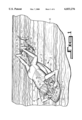
- FIG. 1 is a perspective view of the present invention being used in a body of water.
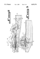
- FIG. 2 is a side view taken in the direction of arrow 2 in FIG. 1.
- FIG. 3 is a front view taken in the direction of arrow 3 in FIG. 2.
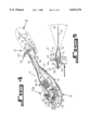
- FIG. 4 is a perspective view of the present invention per se.
- FIG. 5 is a top view taken in the direction of arrow 5 in FIG. 4, with the forward portion broken away.
- FIG. 6 is an enlarged exploded perspective view of an area in FIG. 4 indicated by arrow 6.
- FIG. 7 is an enlarged perspective view of an area in FIG. 4 indicated by arrow 7.
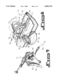
- FIG. 8 is an enlarged perspective view similar to FIG. 7 of an area in FIG. 4 indicated by arrow 8, showing the adjustment feature of the shoulder support pad assembly.
- FIG. 9 is a further enlarged perspective view of an area in FIG. 8, with parts broken away, showing the adjustment feature of the steering gear unit.
- FIG. 10 is an enlarged exploded perspective view of an area in FIG. 4 indicated by arrow 10.
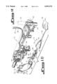
- FIG. 11 is a further enlarged perspective view taken in the direction of arrow 11 in FIG. 10, with parts broken away and shown in phantom.
- FIGS. 1 through 11 illustrate the present invention being a personal water vehicle 12.
- the following numbering is used throughout the various drawing figures.
- the personal water vehicle 12 comprises a structure 14 for supporting a person 16 in a prone position above an upper surface of a body of water 18.
- a facility 20 is for steering the supporting structure 14 in the body of water 18, using manual operation by the hands 22 of the person 16.
- An assemblage 24 is for propelling the supporting structure 14 in the body of water 18, using peddle movement by the feet 26 of the person 16.
- a device 28 for viewing, extends through the supporting structure 14, so that the person 16 can look into the body of water 18.
- the supporting structure 14 is a buoyant support member 30 being hollow, having a bow, stern, deck and hull and fabricated out of a rigid material.
- the buoyant support member 30 includes an upper body support portion 32 for supporting the upper body 34 of the person 16 in the prone position amidships.
- a flat streamlined head portion 36 extends forward of the upper body support portion 32.
- An elongated stem portion 38 extends aft of the upper body support portion 32, to supply clearance for the legs 40 of the person 16 during peddling movement by the feet 26.
- the steering facility 20 consists of a pair of adjustable shoulder support pad assemblies 42, each having a grip handle 44 and mounted spaced apart on a forward end of the supporting structure 14 adjacent the starboard side and the port side thereof.
- the shoulders 46 of the person 16 can engage with the adjustable shoulder support pad assemblies 42, while the hands 22 of the person can grasp the grip handles 44.
- a pair of adjustable cable control gear units 48 are provided. Each adjustable cable control gear unit 48 is carried in a forward end of one adjustable shoulder support pad assembly 42.
- a pair of steering levers 50 are also provided. Each steering lever 50 is connected to one adjustable cable control gear unit 48 adjacent one grip handle 44, so as to be manually operable by one hand 22 of the person 16.
- a tail fin assembly 52 is mounted to a rearward end of the supporting structure 14.
- a steering gear unit 54 is carried in the tail fin assembly 52.
- a pair of elongated steering control cables 56 extend between the adjustable cable control gear units 48 and the steering gear unit 54.
- the propelling assemblage 24 comprises a swivel pedal assembly 58, pivotally mounted over the rearward end of the supporting structure 14 at the tail fin assembly 52.
- a pair of toe clip foot hanger pedals 60 are provided with each mounted on an opposite end of the swivel pedal assembly 58, to engage with one foot 26 of the person 16.
- a propulsion gear box 62 is carried in the tail fin assembly 52 in conjunction with the steering gear unit 54.
- the tail fin assembly 52 includes a vertical stabilizer 64 attached in a removable manner to the rearward end of the supporting structure 14.
- a pedal mount 66 is on the vertical stabilizer 64.
- a gear housing 68 receives the propulsion gear box 62 and the steering gear unit 54 therein, so that a pedal column 70 of the swivel pedal assembly 58 can extend upwardly from the propulsion gear box 62 and through the pedal mount 66.
- a housing cap 72 with a flexible rubber cover 74 and tail fin mount base 76 engages with the gear housing 68.
- a tail fin 78 is secured to a shaft 80 of the propulsion gear box 62 and the steering gear unit 54 at the tail fin mount base 76 of the housing cap 72.
- the viewing device 28 is a see through window 82.
- the see through window 82 consists of a transparent plastic lens 84 extending centrally through the supporting structure 14 adjacent a front end thereof.
- a soft rubber face piece 86 is mounted over the lens 84 in a detachable manner.
- the face piece 86 has an air and water extractor vent 88, to release any air and water when the person 16 places their face 90 against the face piece 86.
- the buoyant support member 30, as best seen in FIG. 4, further includes the upper body support portion 32 having a storage compartment 92 therein for holding various items needed by the person 16.
- the storage compartment 92 contains a cover 94 with a hinge 96 between the cover 94 and the storage compartment 92.
- a latch mechanism 98 is between the cover 94 and the storage compartment 92 opposite from the hinge 96, so as to keep the cover 94 closed over the storage compartment 92.
Landscapes
- Engineering & Computer Science (AREA)
- Mechanical Engineering (AREA)
- Ocean & Marine Engineering (AREA)
- Chemical & Material Sciences (AREA)
- Combustion & Propulsion (AREA)
- Physics & Mathematics (AREA)
- Acoustics & Sound (AREA)
- Toys (AREA)
Abstract
A personal water vehicle (12) comprising a structure (14) for supporting a person (16) in a prone position above an upper surface of a body of water (18). A facility (20) is for steering the supporting structure (14) in the body of water (18), using manual operation by the hands (22) of the person (16). An assemblage (24) is for propelling the supporting structure (14) in the body of water (18), using peddle movement by the feet (26) of the person (16). A device (28) for viewing, extends through the supporting structure (14), so that the person (16) can look into the body of water (18).
Description
1. Field of the Invention
The instant invention relates generally to watercrafts and more specifically it relates to a personal water vehicle. The personal water vehicle allows a person in a prone position on a buoyant support member, to manually steer by hand and pedal by foot to cause a tail fin assembly to work as a rudder and also undulate like a fish tail in a body of water, to propel it forward for a safe and exciting outdoor water adventure activity. The personal water vehicle contains a see through window, so that the person in the prone position on the buoyant support member can look into the body of water for sightseeing, researching and hunting.
2. Description of the Prior Art
Numerous watercrafts have been provided in prior art. For example, U.S. Pat. No. 4,172,427 to Kindred; U.S. Pat. No. 4,389,195 to Sohaei; U.S. Pat. No. 4,840,592 to Anderson; U.S. Pat. No. 4,925,417 to Warren; U.S. Pat. No. 5,127,855 to Heywood and G.B. Patent Numbered 1,397,456 all are illustrative of such prior art. While these units may be suitable for the particular purpose to which they address, they would not be as suitable for the purposes of the present invention as heretofore described.
U.S. Pat. No. 4,172,427
A propulsion unit for driving watercraft, particularly those of the floating lounge type, is disclosed as including a fin made from a flexible material with a first end formed to define a foil into which the lower end of an oscillatory drive member projects downwardly in a fixedly secured relationship and with a second flexible fin end that extends from the foil end to provide a flapping movement through the water upon oscillation of the drive member in order to propel the watercraft. Movement of the drive member through the water is facilitated by the foil shape of the first fin end which is also more rigid than the second flexible end, so as to increase the moment arm about the drive member where the flexible flapping movement is concentrated. Flexible sheet plastic is preferably used to form the fin with a folding operation at a score line to define the foil shape. A journal in the form of a tube receives an intermediate portion of the drive member to provide mounting thereof and is connected to the first end of a mounting bar which has a pair of spaced mounts for securing the unit to the frame of a water lounge. One of the mounts includes a saddle-like member and a cooperable fastener for securing the first end of the mounting bar to the frame. The other mount may include either a flattened hook shape portion of a second end of the mounting bar and a cooperable fastener or a flattened portion of the second mounting bar end which is inserted within a hole in the lounge frame. A foot actuator bar for the unit is secured to the upper end of the drive member, either by a welded connection or a hollow T-shaped connector. Best results are achieved when the length of the flexible fin end is between about 1.4 and 1.8 times the length of the foil fin end.
A steerable, self-propellable surfboard has a steering arrangement attached to a weight-bearing buoyant member such as normally forms a surfboard and arranged for being actuatable by a surfer lying prone on the buoyant member and permitting the surfboard to be maneuvered under control through a liquid in which the surfboard is disposed. The steering arrangement includes a rudder assembly arranged for changing a direction of travel of the surfboard, and a fin assembly which permits the surfer to propel the surfboard through a calm liquid body by causing the member to fish tail or undulate through the liquid in which the surfboard is traveling.
An underwater viewing platform is described which has a stern mounted electric drive motor whose direction and speed may be varied by forward mounted controls located adjacent the prone-lying operator's hands near a large forward mounted viewing window. A shade cowl arches up over the viewing window and has a U-shaped stern-facing, padded opening for receiving the operator's head. With the operator's head in place, the large viewing window is substantially shaded from overhead sunlight and has a large viewing angle and field view. The window has a lens for providing the desired degree of magnification or demagnification. Bottom illumination is provided by an underwater light for night time use. Navigation and battery status and drain instruments are conveniently mounted within or on the shade cowl. Various design features reduce operator fatigue and extend useful range and endurance. End useful range and endurance.
An apparatus for underwater surveillance that consists of a floating platform having bow and stern with an aerodynamically true forward cowl formed on the bow end, the forward approximately one-third of the platform. Immediately aft of the cowl there is disposed a viewing assembly placed in a clearance formed centrally through the platform, and the viewing assembly is a tightly sealed transparent member having top panel, bottom panel and side panel and defining a volume that is maintained liquid free thereby to enable maximum viewing efficiency at all times.
A water-borne vehicle with floats, a frame which is mounted on the floats providing a seat and a steering mechanism, and a propulsion means for propelling the vehicle in the water. The propulsion means comprises a plate which is generally parallel to the surface of the water and which is displaced up and down by a foot pedalled crank. A connecting arm is attached at one end rigidly and perpendicularly to the plate and at the opposite end to the crank. The horizontal position of the plate is maintained by an upright member which is slideably retained between rollers that maintain its upright position and is pivotally attached to the plate. As the crank is rotated, one end of the connecting arm follows a circular path, displacing the plate upward and downward. As the plate oscillates up and down, the upright member slides up and down between the rollers and maintains the horizontal position of the plate as directly below the upright member. The angle of the plane of the plate with respect to the surface of the water is varied during the up and down motion of the plate to effect a rearward force on the water, propelling the vehicle forward.
A buoyant board comprising a rigid, substantially flat, elongate base portion, of buoyant material. A pair of elongate fins extend generally longitudinally of the base portion and project from the underside surface thereof, such as to be substantially equally spaced from the longitudinal axis of the base portion. The base portion has an aperture therethrough, the axial ends of which are closed by respective sheets of a transparent material, so as to form an observation window through the base portion.
A primary object of the present invention is to provide a personal water vehicle that will overcome the shortcomings of the prior art devices.
Another object is to provide a personal water vehicle in which a person in a prone position on a buoyant support member can manually steer by hand and pedal by foot to cause a tail fin assembly to work as a rudder and also undulate like a fish tail in a body of water, to propel it forward for a safe and exciting outdoor water adventure activity.
An additional object is to provide a personal water vehicle with a see through window, so that the person in the prone position on the buoyant support member can look into the body of water for sightseeing, researching and hunting.
A further object is to provide a personal water vehicle that is simple and easy to use.
A still further object is to provide a personal water vehicle that is economical in cost to manufacture.
Further objects of the invention will appear as the description proceeds.
To the accomplishment of the above and related objects, this invention may be embodied in the form illustrated in the accompanying drawings, attention being called to the fact, however, that the drawings are illustrative only, and that changes may be made in the specific construction illustrated and described within the scope of the appended claims.
Various other objects, features and attendant advantages of the present invention will become more fully appreciated as the same becomes better understood when considered in conjunction with the accompanying drawings, in which like reference characters designate the same or similar parts throughout the several views, and wherein;
FIG. 1 is a perspective view of the present invention being used in a body of water.
FIG. 2 is a side view taken in the direction of arrow 2 in FIG. 1.
FIG. 3 is a front view taken in the direction of arrow 3 in FIG. 2.
FIG. 4 is a perspective view of the present invention per se.
FIG. 5 is a top view taken in the direction of arrow 5 in FIG. 4, with the forward portion broken away.
FIG. 6 is an enlarged exploded perspective view of an area in FIG. 4 indicated by arrow 6.
FIG. 7 is an enlarged perspective view of an area in FIG. 4 indicated by arrow 7.
FIG. 8 is an enlarged perspective view similar to FIG. 7 of an area in FIG. 4 indicated by arrow 8, showing the adjustment feature of the shoulder support pad assembly.
FIG. 9 is a further enlarged perspective view of an area in FIG. 8, with parts broken away, showing the adjustment feature of the steering gear unit.
FIG. 10 is an enlarged exploded perspective view of an area in FIG. 4 indicated by arrow 10.
FIG. 11 is a further enlarged perspective view taken in the direction of arrow 11 in FIG. 10, with parts broken away and shown in phantom.
Similar reference characters denote corresponding features consistently throughout the attached drawings.
Turning now descriptively to the drawings, in which similar reference characters denote similar elements throughout the several views, FIGS. 1 through 11 illustrate the present invention being a personal water vehicle 12. With regard to the reference numerals used, the following numbering is used throughout the various drawing figures.
______________________________________
   12      personal water vehicle
14          supporting structure of 12
16          person
18          body of water
20           steering facility of 12
22           hand of 16
24           propelling assemblage of 12
26           foot of 16
28           viewing device of 12
30           buoyant support member for 14
32           upper body support portion of 30
34           upper body of 16
36          flat streamlined head portion of 30
38          elongated stem portion of 30
40          leg of 16
42          adjustable shoulder support pad assembly
               of 20
44          grip handle on 42
46          shoulder of 16
48          adjustable cable control gear unit of 20
50          steering lever of 20
52           tail fin assembly of 20
54           steering gear unit of 20
56           elongated steering control cables of 20
58           swivel pedal assembly of 24
60           toe clip foot hanger pedal of 24
62           propulsion gear box of 24
64           vertical stabilizer of 52
66           pedal mount of 52
68          gear housing of 52
70          pedal column of 58
72          housing cap of 52
74          flexible rubber cover on 72
76          tail fin mount base on 74
78          tail fin of 52
80          shaft of 62 and 54
82          see through window for 28
84          transparent plastic lens of 82
86          soft rubber face piece of 82
88          air and water extractor vent in 86
90          face of 16
92          storage compartment in 32 of 30
94          cover of 92
96          hinge between 94 and 92
98          latch mechanism between 94 and 92
______________________________________
The personal water vehicle 12 comprises a structure 14 for supporting a person 16 in a prone position above an upper surface of a body of water 18. A facility 20 is for steering the supporting structure 14 in the body of water 18, using manual operation by the hands 22 of the person 16. An assemblage 24 is for propelling the supporting structure 14 in the body of water 18, using peddle movement by the feet 26 of the person 16. A device 28 for viewing, extends through the supporting structure 14, so that the person 16 can look into the body of water 18.
The supporting structure 14 is a buoyant support member 30 being hollow, having a bow, stern, deck and hull and fabricated out of a rigid material. The buoyant support member 30 includes an upper body support portion 32 for supporting the upper body 34 of the person 16 in the prone position amidships. A flat streamlined head portion 36 extends forward of the upper body support portion 32. An elongated stem portion 38 extends aft of the upper body support portion 32, to supply clearance for the legs 40 of the person 16 during peddling movement by the feet 26.
The steering facility 20 consists of a pair of adjustable shoulder support pad assemblies 42, each having a grip handle 44 and mounted spaced apart on a forward end of the supporting structure 14 adjacent the starboard side and the port side thereof. The shoulders 46 of the person 16 can engage with the adjustable shoulder support pad assemblies 42, while the hands 22 of the person can grasp the grip handles 44. A pair of adjustable cable control gear units 48 are provided. Each adjustable cable control gear unit 48 is carried in a forward end of one adjustable shoulder support pad assembly 42. A pair of steering levers 50 are also provided. Each steering lever 50 is connected to one adjustable cable control gear unit 48 adjacent one grip handle 44, so as to be manually operable by one hand 22 of the person 16. A tail fin assembly 52 is mounted to a rearward end of the supporting structure 14. A steering gear unit 54 is carried in the tail fin assembly 52. A pair of elongated steering control cables 56 extend between the adjustable cable control gear units 48 and the steering gear unit 54. When each of the steering levers 50 are manually operated by the hands 22 of the person 16, the tail fin assembly 52 will swivel left and right to steer the supporting structure 14.
The propelling assemblage 24 comprises a swivel pedal assembly 58, pivotally mounted over the rearward end of the supporting structure 14 at the tail fin assembly 52. A pair of toe clip foot hanger pedals 60 are provided with each mounted on an opposite end of the swivel pedal assembly 58, to engage with one foot 26 of the person 16. A propulsion gear box 62 is carried in the tail fin assembly 52 in conjunction with the steering gear unit 54. When the swivel pedal assembly 58 is rocked forward and rearward by the peddle movement of the feet 26 of the person 16 engaging the toe clip foot hanger pedals 60, the tail fin assembly 52 will undulate like a fish tail in the body of water 18 to drive the supporting structure 14 forward in the body of water 18.
The tail fin assembly 52 includes a vertical stabilizer 64 attached in a removable manner to the rearward end of the supporting structure 14. A pedal mount 66 is on the vertical stabilizer 64. A gear housing 68 receives the propulsion gear box 62 and the steering gear unit 54 therein, so that a pedal column 70 of the swivel pedal assembly 58 can extend upwardly from the propulsion gear box 62 and through the pedal mount 66. A housing cap 72 with a flexible rubber cover 74 and tail fin mount base 76 engages with the gear housing 68. A tail fin 78 is secured to a shaft 80 of the propulsion gear box 62 and the steering gear unit 54 at the tail fin mount base 76 of the housing cap 72.
The viewing device 28 is a see through window 82. The see through window 82 consists of a transparent plastic lens 84 extending centrally through the supporting structure 14 adjacent a front end thereof. A soft rubber face piece 86 is mounted over the lens 84 in a detachable manner. The face piece 86 has an air and water extractor vent 88, to release any air and water when the person 16 places their face 90 against the face piece 86.
The buoyant support member 30, as best seen in FIG. 4, further includes the upper body support portion 32 having a storage compartment 92 therein for holding various items needed by the person 16. The storage compartment 92 contains a cover 94 with a hinge 96 between the cover 94 and the storage compartment 92. A latch mechanism 98 is between the cover 94 and the storage compartment 92 opposite from the hinge 96, so as to keep the cover 94 closed over the storage compartment 92.
It will be understood that each of the elements described above, or two or more together may also find a useful application in other types of methods differing from the type described above.
While certain novel features of this invention have been shown and described are pointed out in the annexed claims, it is not intended to be limited to the details above, since it will be understood that various omissions, modifications, substitutions and changes in the forms and details of the device illustrated and in its operation can be made by those skilled in the art without departing in any way from the spirit of the present invention.
Without further analysis, the foregoing will so fully reveal the gist of the present invention that others can, by applying current knowledge, readily adapt it for various applications without omitting features that, from the standpoint of prior art, fairly constitute essential characteristics of the generic or specific aspects of this invention.
Claims (15)
1. A personal water vehicle comprising:
a) means for supporting a person in a prone position above an upper surface of a body of water;
b) means for steering said supporting means in the body of water, using manual operation by the hands of the person, said steering means including;
i) a pair of adjustable shoulder support pad assemblies, each having a grip handle and mounted spaced apart on a forward end of said supporting means adjacent the starboard side and the port side thereof, so that the shoulders of the person can engage with said adjustable shoulder support pad assemblies, while the hands of the person can grasp said grip handles;
ii) a pair of adjustable cable control gear units, in which each said adjustable cable control gear unit is carried in a forward end of one of said adjustable shoulder support pad assemblies;
iii) a pair of steering levers, in which each said steering lever is connected to one said adjustable cable control gear unit adjacent one said grip handle, so as to be manually operable by one hand of the person;
iv) a tail fin assembly mounted to a rearward end of said supporting means;
v) a steering gear unit carried in said tail fin assembly; and
vi) a pair of elongated steering control cables extending between said adjustable cable control gear unit and said steering gear unit, so that when each of said steering levers are manually operated by the hands of the person said tail fin assembly will swivel left and right to steer said supporting means;
c) means for propelling said supporting means in the body of water, using peddle movement by the feet of the person; and
d) means for viewing, extending through said supporting means, so that the person can look into the body of water.
2. A personal water vehicle as recited in claim 1, wherein said supporting means is a buoyant support member being hollow, having a bow, stern, deck and hull and fabricated out of a rigid material.
3. A personal water vehicle as recited in claim 2, wherein said buoyant support member includes:
a) an upper body support portion for supporting the upper body of the person in the prone position amidships;
b) a flat streamlined head portion extending forward of said upper body support portion; and
c) an elongated stem portion extending aft of said upper body support portion, to supply clearance for the legs of the person during peddling movement by the feet.
4. A personal water vehicle as recited in claim 1, wherein said propelling means includes:
a) a swivel pedal assembly pivotally mounted over the rearward end of said supporting means at said tail fin assembly;
b) a pair of toe clip foot hanger pedals, each mounted on an opposite end of said swivel pedal assembly to engage with one foot of the person;
c) a propulsion gear box carried in said tail fin assembly in conjunction with said steering gear unit, so that when said swivel pedal assembly is rocked forward and rearward by the peddle movement of the feet of the person engaging said toe clip foot hanger pedals, said tail fin assembly will undulate like a fish tail in the body of water to drive said supporting means forward in the body of water.
5. A personal water vehicle as recited in claim 4, wherein said tail fin assembly includes:
a) a vertical stabilizer attached in a removable manner to the rearward end of said supporting means;
b) a pedal mount on said vertical stabilizer;
c) a gear housing to receive said propulsion gear box and said steering gear unit therein, so that a pedal column of said swivel pedal assembly can extend upwardly from said propulsion gear box and through said pedal mount;
d) a housing cap with a flexible rubber cover and tail fin mount base to engage with said gear housing; and
e) a tail fin secured to a shaft of said propulsion gear box and said steering gear unit at said tail fin mount base of said housing cap.
6. A personal water vehicle as recited in claim 1, wherein said viewing means is a see through window.
7. A personal water vehicle as recited in claim 6, wherein said see through window includes:
a) a transparent plastic lens extending centrally through said supporting means adjacent a front end thereof; and
b) a soft rubber face piece mounted over said lens in a detachable manner, said face piece having an air and water extractor vent to release any air and water when the person places their face against said face piece.
8. A personal water vehicle as recited in claim 3, wherein said buoyant support member further includes said upper body support portion having a storage compartment therein for holding various items needed by the person.
9. A personal water vehicle as recited in claim 8, wherein said storage compartment includes:
a) a cover;
b) a hinge between said cover and said storage compartment; and
c) a latch mechanism between said cover and said storage compartment opposite from said hinge, so as to keep said cover closed over said storage compartment.
10. A personal water vehicle as recited in claim 3, wherein said propelling means includes:
a) a swivel pedal assembly pivotally mounted over the rearward end of said supporting means at said tail fin assembly;
b) a pair of toe clip foot hanger pedals, each mounted on an opposite end of said swivel pedal assembly to engage with one foot of the person;
c) a propulsion gear box carried in said tail fin assembly in conjunction with said steering gear unit, so that when said swivel pedal assembly is rocked forward and rearward by the peddle movement of the feet of the person engaging said toe clip foot hanger pedals, said tail fin assembly will undulate like a fish tail in the body of water to drive said supporting means forward in the body of water.
11. A personal water vehicle as recited in claim 10, wherein said tail fin assembly includes:
a) a vertical stabilizer attached in a removable manner to the rearward end of said supporting means;
b) a pedal mount on said vertical stabilizer;
c) a gear housing to receive said propulsion gear box and said steering gear unit therein, so that a pedal column of said swivel pedal assembly can extend upwardly from said propulsion gear box and through said pedal mount;
d) a housing cap with a flexible rubber cover and tail fin mount base to engage with said gear housing; and
e) a tail fin secured to a shaft of said propulsion gear box and said steering gear unit at said tail fin mount base of said housing cap.
12. A personal water vehicle as recited in claim 11, wherein said viewing means is a see through window.
13. A personal water vehicle as recited in claim 12, wherein said see through window includes:
a) a transparent plastic lens extending centrally through said supporting means adjacent a front end thereof; and
b) a soft rubber face piece mounted over said lens in a detachable manner, said face piece having an air and water extractor vent to release any air and water when the person places their face against said face piece.
14. A personal water vehicle as recited in claim 13, wherein said buoyant support member further includes said upper body support portion having a storage compartment therein for holding various items needed by the person.
15. A personal water vehicle as recited in claim 14, wherein said storage compartment includes:
a) a cover;
b) a hinge between said cover and said storage compartment; and
c) a latch mechanism between said cover and said storage compartment opposite from said hinge, so as to keep said cover closed over said storage compartment.
Priority Applications (1)
| Application Number | Priority Date | Filing Date | Title |
|---|---|---|---|
| US09/134,960 US6033276A (en) | 1998-08-17 | 1998-08-17 | Personal water vehicle |
Applications Claiming Priority (1)
| Application Number | Priority Date | Filing Date | Title |
|---|---|---|---|
| US09/134,960 US6033276A (en) | 1998-08-17 | 1998-08-17 | Personal water vehicle |
Publications (1)
| Publication Number | Publication Date |
|---|---|
| US6033276A true US6033276A (en) | 2000-03-07 |
Family
ID=22465818
Family Applications (1)
| Application Number | Title | Priority Date | Filing Date |
|---|---|---|---|
| US09/134,960 Expired - Fee Related US6033276A (en) | 1998-08-17 | 1998-08-17 | Personal water vehicle |
Country Status (1)
| Country | Link |
|---|---|
| US (1) | US6033276A (en) |
Cited By (28)
| Publication number | Priority date | Publication date | Assignee | Title |
|---|---|---|---|---|
| USD449868S1 (en) | 2001-01-22 | 2001-10-30 | Thomas W. Rogers | Aquatic vehicle |
| US6375530B1 (en) * | 2001-01-31 | 2002-04-23 | Milan Dennis Earl | Whaletail swimming device |
| US6468118B1 (en) | 2000-11-08 | 2002-10-22 | Cid, Inc. | Personal watercraft |
| US6524145B1 (en) * | 2001-07-12 | 2003-02-25 | Jesse Gallegos Arzate | Swimmer propulsion device |
| US6558210B2 (en) | 2001-08-29 | 2003-05-06 | Charles Consolvo Frasier | Device for propelling a diver through a body of water using pedaling motion |
| US6612254B1 (en) * | 1999-11-08 | 2003-09-02 | Brian Frank Arthur | Towable underwater kite |
| KR100520006B1 (en) * | 2004-05-19 | 2005-10-10 | 유재형 | Oar projectile apparatus |
| GB2414715A (en) * | 2004-05-06 | 2005-12-07 | Yo Bro Ltd | Manually propelled water-borne craft with underwater viewing portal |
| CN1302213C (en) * | 2001-01-01 | 2007-02-28 | 熊介良 | 'Menneimasi pendulum arm' and flapping-wing propeller |
| US20080262666A1 (en) * | 2007-04-20 | 2008-10-23 | Manning Doug | Powered riding apparatus with electronic controls and options |
| US20090042462A1 (en) * | 2007-08-06 | 2009-02-12 | Deka Products Limited Partnership | Swimming Propulsion Device |
| US7699017B1 (en) * | 2008-05-12 | 2010-04-20 | Marshall Donald K | Personal undersea observation pedal craft |
| US7841914B1 (en) * | 2008-11-25 | 2010-11-30 | Josue Gonzalez | Floating apparatus with manual driver |
| USD652780S1 (en) * | 2011-03-23 | 2012-01-24 | Wemesfelder William R | Flotation apparatus |
| KR101174219B1 (en) | 2010-10-13 | 2012-08-14 | 동국대학교 산학협력단 | Exercise boat for water sports |
| US20120276792A1 (en) * | 2011-04-29 | 2012-11-01 | Marc Martino | Human powered watercraft |
| US20140098215A1 (en) * | 2011-05-10 | 2014-04-10 | Alain Dinis | Method and device for viewing computer data contents associated with propulsion |
| US20150079860A1 (en) * | 2013-09-19 | 2015-03-19 | Lakdas Nanayakkara | Surfboard With Safety Mechanism |
| US9090317B2 (en) | 2012-04-24 | 2015-07-28 | Thomas Charles Mulvihill | Flotation device having a window and a mask to permit a user to view below the water |
| US20150321738A1 (en) * | 2014-05-07 | 2015-11-12 | David Scott Doherty | Buoyant viewing platform |
| US9365272B1 (en) | 2015-09-17 | 2016-06-14 | Silvino R. Foglia | Hand crank stand-up paddle board |
| US9522719B1 (en) * | 2015-07-20 | 2016-12-20 | Robert Yonover | Watercraft driven by a reciprocating fin |
| US10071792B2 (en) * | 2013-01-10 | 2018-09-11 | Julien Montousse | Underwater personal submersible |
| US20190039703A1 (en) * | 2017-08-01 | 2019-02-07 | William Kohnen | Swimming apparatus |
| WO2020071929A1 (en) * | 2018-10-05 | 2020-04-09 | Kurt Franz Meinel Cheesman | Individual device for aquatic propulsion |
| US20200189702A1 (en) * | 2018-05-11 | 2020-06-18 | LightSUP Boards, LLC | Stand up paddle board with window and lights |
| USD914120S1 (en) | 2019-05-09 | 2021-03-23 | LightSUP Boards, LLC | Stand up paddle board with transparent viewing window |
| US12497139B2 (en) | 2018-10-22 | 2025-12-16 | Drew Allen Krah | Diver propulsion device |
Citations (3)
| Publication number | Priority date | Publication date | Assignee | Title |
|---|---|---|---|---|
| US2926365A (en) * | 1955-09-02 | 1960-03-01 | American Mach & Foundry | Swimming and underwater viewing apparatus |
| US2990805A (en) * | 1958-12-15 | 1961-07-04 | Jacus Joseph | Aquatic device |
| US3042945A (en) * | 1959-05-19 | 1962-07-10 | William M Saeman | Swimmer's sled |
-
1998
- 1998-08-17 US US09/134,960 patent/US6033276A/en not_active Expired - Fee Related
Patent Citations (3)
| Publication number | Priority date | Publication date | Assignee | Title |
|---|---|---|---|---|
| US2926365A (en) * | 1955-09-02 | 1960-03-01 | American Mach & Foundry | Swimming and underwater viewing apparatus |
| US2990805A (en) * | 1958-12-15 | 1961-07-04 | Jacus Joseph | Aquatic device |
| US3042945A (en) * | 1959-05-19 | 1962-07-10 | William M Saeman | Swimmer's sled |
Cited By (36)
| Publication number | Priority date | Publication date | Assignee | Title |
|---|---|---|---|---|
| US6612254B1 (en) * | 1999-11-08 | 2003-09-02 | Brian Frank Arthur | Towable underwater kite |
| US6468118B1 (en) | 2000-11-08 | 2002-10-22 | Cid, Inc. | Personal watercraft |
| CN1302213C (en) * | 2001-01-01 | 2007-02-28 | 熊介良 | 'Menneimasi pendulum arm' and flapping-wing propeller |
| USD449868S1 (en) | 2001-01-22 | 2001-10-30 | Thomas W. Rogers | Aquatic vehicle |
| US6375530B1 (en) * | 2001-01-31 | 2002-04-23 | Milan Dennis Earl | Whaletail swimming device |
| US6524145B1 (en) * | 2001-07-12 | 2003-02-25 | Jesse Gallegos Arzate | Swimmer propulsion device |
| US6558210B2 (en) | 2001-08-29 | 2003-05-06 | Charles Consolvo Frasier | Device for propelling a diver through a body of water using pedaling motion |
| GB2414715A (en) * | 2004-05-06 | 2005-12-07 | Yo Bro Ltd | Manually propelled water-borne craft with underwater viewing portal |
| KR100520006B1 (en) * | 2004-05-19 | 2005-10-10 | 유재형 | Oar projectile apparatus |
| US20080262666A1 (en) * | 2007-04-20 | 2008-10-23 | Manning Doug | Powered riding apparatus with electronic controls and options |
| US8290636B2 (en) * | 2007-04-20 | 2012-10-16 | Manning Doug | Powered riding apparatus with electronic controls and options |
| US20090042462A1 (en) * | 2007-08-06 | 2009-02-12 | Deka Products Limited Partnership | Swimming Propulsion Device |
| US7988508B2 (en) | 2007-08-06 | 2011-08-02 | Deka Products Limited Partnership | Swimming propulsion device |
| US7699017B1 (en) * | 2008-05-12 | 2010-04-20 | Marshall Donald K | Personal undersea observation pedal craft |
| US7841914B1 (en) * | 2008-11-25 | 2010-11-30 | Josue Gonzalez | Floating apparatus with manual driver |
| KR101174219B1 (en) | 2010-10-13 | 2012-08-14 | 동국대학교 산학협력단 | Exercise boat for water sports |
| USD652780S1 (en) * | 2011-03-23 | 2012-01-24 | Wemesfelder William R | Flotation apparatus |
| US20120276792A1 (en) * | 2011-04-29 | 2012-11-01 | Marc Martino | Human powered watercraft |
| US8763551B2 (en) * | 2011-04-29 | 2014-07-01 | Marc Gregory Martino | Human powered watercraft |
| US20140098215A1 (en) * | 2011-05-10 | 2014-04-10 | Alain Dinis | Method and device for viewing computer data contents associated with propulsion |
| US9591271B2 (en) * | 2011-05-10 | 2017-03-07 | Alain Dinis | Method and device for viewing computer data contents associated with propulsion |
| US9090317B2 (en) | 2012-04-24 | 2015-07-28 | Thomas Charles Mulvihill | Flotation device having a window and a mask to permit a user to view below the water |
| US10071792B2 (en) * | 2013-01-10 | 2018-09-11 | Julien Montousse | Underwater personal submersible |
| US20150079860A1 (en) * | 2013-09-19 | 2015-03-19 | Lakdas Nanayakkara | Surfboard With Safety Mechanism |
| US9067652B2 (en) * | 2013-09-19 | 2015-06-30 | Lakdas Nanayakkara | Surfboard with safety mechanism |
| US20150321738A1 (en) * | 2014-05-07 | 2015-11-12 | David Scott Doherty | Buoyant viewing platform |
| US9522719B1 (en) * | 2015-07-20 | 2016-12-20 | Robert Yonover | Watercraft driven by a reciprocating fin |
| US9365272B1 (en) | 2015-09-17 | 2016-06-14 | Silvino R. Foglia | Hand crank stand-up paddle board |
| US20190039703A1 (en) * | 2017-08-01 | 2019-02-07 | William Kohnen | Swimming apparatus |
| US10745093B2 (en) * | 2017-08-01 | 2020-08-18 | William Kohnen | Swimming apparatus |
| US20200189702A1 (en) * | 2018-05-11 | 2020-06-18 | LightSUP Boards, LLC | Stand up paddle board with window and lights |
| US10850816B2 (en) * | 2018-05-11 | 2020-12-01 | LightSUP Boards, LLC | Stand up paddle board with window and lights |
| WO2020071929A1 (en) * | 2018-10-05 | 2020-04-09 | Kurt Franz Meinel Cheesman | Individual device for aquatic propulsion |
| US11697481B2 (en) | 2018-10-05 | 2023-07-11 | Kurt Franz Meinel Cheesman | Individual device for aquatic propulsion |
| US12497139B2 (en) | 2018-10-22 | 2025-12-16 | Drew Allen Krah | Diver propulsion device |
| USD914120S1 (en) | 2019-05-09 | 2021-03-23 | LightSUP Boards, LLC | Stand up paddle board with transparent viewing window |
Similar Documents
| Publication | Publication Date | Title |
|---|---|---|
| US6033276A (en) | Personal water vehicle | |
| US4840592A (en) | Power driven underwater viewing platform | |
| EP3016852B1 (en) | Stand up mirage watercraft | |
| US7931512B2 (en) | Manually operated watercraft | |
| US5094638A (en) | Water vehicle | |
| US20050217555A1 (en) | Marine propulsion attachment wirh removable frame structure for non-self-propelled marine vehicles | |
| US9533746B1 (en) | Human powered watercraft propulsion device | |
| US4350113A (en) | Motorized floatboard | |
| US7699017B1 (en) | Personal undersea observation pedal craft | |
| US4345903A (en) | Fin propulsion boat | |
| US5217398A (en) | Pedal operated catamaran | |
| US7189127B2 (en) | Watercraft propulsion machine | |
| US6165030A (en) | Pedal driven propulsion device | |
| US6347599B1 (en) | Stabilization/power system for windsurfing and other flotation boards | |
| US4676755A (en) | Pedal driven device | |
| US7234404B2 (en) | Water craft with a sail | |
| US3394673A (en) | Water ski scooter | |
| US4512275A (en) | Unsinkable all-purpose boat | |
| US6843691B1 (en) | Sculling apparatus for small boats | |
| US10543894B2 (en) | Self-powered standup personal watercraft | |
| CA2297718A1 (en) | Personal water vehicle | |
| JP4240477B2 (en) | Extremely small water vehicle propulsion device | |
| US4324551A (en) | Bow-mounted propeller driven boat | |
| US5067427A (en) | Semi-submerged water vehicle | |
| US9365272B1 (en) | Hand crank stand-up paddle board |
Legal Events
| Date | Code | Title | Description |
|---|---|---|---|
| REMI | Maintenance fee reminder mailed | ||
| LAPS | Lapse for failure to pay maintenance fees | ||
| FP | Lapsed due to failure to pay maintenance fee |
Effective date: 20040307 |
|
| STCH | Information on status: patent discontinuation |
Free format text: PATENT EXPIRED DUE TO NONPAYMENT OF MAINTENANCE FEES UNDER 37 CFR 1.362 |