US6033183A - Impeller for a rotary pump - Google Patents
Impeller for a rotary pump Download PDFInfo
- Publication number
- US6033183A US6033183A US09/002,622 US262298A US6033183A US 6033183 A US6033183 A US 6033183A US 262298 A US262298 A US 262298A US 6033183 A US6033183 A US 6033183A
- Authority
- US
- United States
- Prior art keywords
- blades
- blade
- defining
- impeller
- free spaces
- Prior art date
- Legal status (The legal status is an assumption and is not a legal conclusion. Google has not performed a legal analysis and makes no representation as to the accuracy of the status listed.)
- Expired - Lifetime
Links
Images
Classifications
-
- B—PERFORMING OPERATIONS; TRANSPORTING
- B29—WORKING OF PLASTICS; WORKING OF SUBSTANCES IN A PLASTIC STATE IN GENERAL
- B29C—SHAPING OR JOINING OF PLASTICS; SHAPING OF MATERIAL IN A PLASTIC STATE, NOT OTHERWISE PROVIDED FOR; AFTER-TREATMENT OF THE SHAPED PRODUCTS, e.g. REPAIRING
- B29C45/00—Injection moulding, i.e. forcing the required volume of moulding material through a nozzle into a closed mould; Apparatus therefor
- B29C45/0053—Injection moulding, i.e. forcing the required volume of moulding material through a nozzle into a closed mould; Apparatus therefor combined with a final operation, e.g. shaping
- B29C45/006—Joining parts moulded in separate cavities
- B29C45/0062—Joined by injection moulding
-
- F—MECHANICAL ENGINEERING; LIGHTING; HEATING; WEAPONS; BLASTING
- F04—POSITIVE - DISPLACEMENT MACHINES FOR LIQUIDS; PUMPS FOR LIQUIDS OR ELASTIC FLUIDS
- F04D—NON-POSITIVE-DISPLACEMENT PUMPS
- F04D29/00—Details, component parts, or accessories
- F04D29/18—Rotors
- F04D29/22—Rotors specially for centrifugal pumps
- F04D29/2205—Conventional flow pattern
- F04D29/2222—Construction and assembly
-
- B—PERFORMING OPERATIONS; TRANSPORTING
- B29—WORKING OF PLASTICS; WORKING OF SUBSTANCES IN A PLASTIC STATE IN GENERAL
- B29L—INDEXING SCHEME ASSOCIATED WITH SUBCLASS B29C, RELATING TO PARTICULAR ARTICLES
- B29L2031/00—Other particular articles
- B29L2031/08—Blades for rotors, stators, fans, turbines or the like, e.g. screw propellers
-
- F—MECHANICAL ENGINEERING; LIGHTING; HEATING; WEAPONS; BLASTING
- F05—INDEXING SCHEMES RELATING TO ENGINES OR PUMPS IN VARIOUS SUBCLASSES OF CLASSES F01-F04
- F05C—INDEXING SCHEME RELATING TO MATERIALS, MATERIAL PROPERTIES OR MATERIAL CHARACTERISTICS FOR MACHINES, ENGINES OR PUMPS OTHER THAN NON-POSITIVE-DISPLACEMENT MACHINES OR ENGINES
- F05C2225/00—Synthetic polymers, e.g. plastics; Rubber
Definitions
- the present invention relates generally to rotary pumps, and more particularly, to an impeller for a rotary pump with an annular upper part defining a central inlet, a drive-adjacent circular disk-shaped lower part, and a plurality of blades secured between the upper and lower parts.
- impellers of the aforementioned kind As a single piece by smelting or from multiple pieces by ultrasound welding. Both manufacturing methods are expensive and fail to result in sufficiently small production tolerances. Further, one can hardly make blades with curvatures in three-dimensional geometry.
- this is achieved by: making the upper and lower parts as separate parts, connectable to each other, forming each blade only on the upper part or only on the lower part, forming each blade with a free edge remote from the connection point to the upper or lower part on which the blade is formed, the free edge having a projection which extends into a recess or opening of the lower part or upper part, when the upper and lower parts are secured together, and forming the recesses or openings with free spaces which, in the assembled state of the upper and lower parts, surround the projections, and into which plastic can be injected, in that assembled state.
- the impeller can be manufactured, without ultrasound welding steps and without smelting, in a one-, two-, three- or four-component process. This can be done in single-workpiece tools with manual insertion or fully automatically in multiple-workpiece tools. In the same tool, one can first injection-mold the upper and lower parts, and then assemble together the upper and lower parts, in order to inject the connecting quantity of plastic.
- every second blade is formed on the upper part, and the blades lying between are formed on the lower part.
- the blades have double the spacing from each other that they will have later in the finished impeller, so that the blades can be made with high precision and in any desired curvature.
- This also means one can provide a large number of blades in the impeller.
- a hub centrally located in the lower part, especially for mounting on the shaft of a drive motor, is formed in the same injection step and of the same plastic injection material as that placed in the free spaces. This way, the hub can be connected to the plastic placed in those free spaces which are in the lower part.
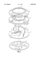
- FIG. 1 illustrates a preferred embodiment of the impeller of the present invention, in an axially exploded view, the plastic connecting masses injected in the last working step into the upper part and lower part being shown separated.
- the impeller of the rotary pump of the present invention is made, in all significant parts, of plastic, and has an annular upper part 1 and a disk-shaped lower part 2. These two parts are secured coaxially to each other, the lower part 2 having a central coaxial hub, with which the impeller can be mounted on the end of a shaft of an electric motor.
- Upper part 1 has, on the side remote from the lower part, a coaxial inlet opening 4, through which the fluid to be pumped is introduced.
- a preferred plastic is polypropylene, reinforced with 20%-40% by weight glass fibers.
- blades 5 interdigit, and projections 7 extend through the free spaces 9 and, in the assembled state, the free spaces 9 are filled with a plastic mass 10.
- This connecting mass 10 is brought to free spaces 9 via coaxial rings 11 to 14.
- Rings 11 and 12 define the outer sides edges of upper part 1 and lower part 2.
- Ring 13 defines the outer edge of inlet opening or intake throat 4.
- Ring 13 is used as an axial mounting on the pump housing wall and thus as a sealing surface on the pump housing inner wall.
- Hub 3 can be a part made separately from parts 1 and 2. However, it can also be injected from the connecting mass, so that ring 14 is injection-molded as a single piece with hub 3. Further, in hub 3, an annular part can be coaxially molded, so form a stop for the shaft end of the drive motor.
- 3-D blades and “three-dimensional blades 5" include doubly-bent or -folded blades, which, in the area of the inlet opening, are oriented with their leading edges 15 in a radial plane inclined with respect to the rotation axis and thereafter, doubly bent, extend between the upper part and the lower part, until they end at the outer rim of the impeller.
Landscapes
- Engineering & Computer Science (AREA)
- Mechanical Engineering (AREA)
- General Engineering & Computer Science (AREA)
- Manufacturing & Machinery (AREA)
- Structures Of Non-Positive Displacement Pumps (AREA)
Abstract
The invention relates to an impeller of a rotary pump having an annular upper part defining a central inlet opening, a drive-adjacent disk-shaped lower part, and a plurality of blades secured between the upper and lower parts. The upper and lower parts are separate parts which secure together. Each blade is integrally formed with either the upper part or the lower part. Every other blade is formed with the upper part, and the remaining blades are formed with the lower part. Each blade has a free edge, remote from a base thereof, which has a projection which extends into a recess or opening formed in the part to which it is not integrally molded. After the upper and lower parts are assembled together, free spaces around the projections are filled with injected plastic, thereby securing the upper and lower parts together and securing the free ends of the blades. This structure and molding process have the advantages of permitting arbitrarily curved impeller blades and facilitating manufacture in a minimum number of operating steps.
Description
The present invention relates generally to rotary pumps, and more particularly, to an impeller for a rotary pump with an annular upper part defining a central inlet, a drive-adjacent circular disk-shaped lower part, and a plurality of blades secured between the upper and lower parts.
It is conventional to manufacture impellers of the aforementioned kind as a single piece by smelting or from multiple pieces by ultrasound welding. Both manufacturing methods are expensive and fail to result in sufficiently small production tolerances. Further, one can hardly make blades with curvatures in three-dimensional geometry.
Accordingly, it is an object of the present invention to improve an impeller of the aforementioned kind to that it can be manufactured simply and economically by as few working steps as possible.
Briefly, this is achieved by: making the upper and lower parts as separate parts, connectable to each other, forming each blade only on the upper part or only on the lower part, forming each blade with a free edge remote from the connection point to the upper or lower part on which the blade is formed, the free edge having a projection which extends into a recess or opening of the lower part or upper part, when the upper and lower parts are secured together, and forming the recesses or openings with free spaces which, in the assembled state of the upper and lower parts, surround the projections, and into which plastic can be injected, in that assembled state.
The impeller can be manufactured, without ultrasound welding steps and without smelting, in a one-, two-, three- or four-component process. This can be done in single-workpiece tools with manual insertion or fully automatically in multiple-workpiece tools. In the same tool, one can first injection-mold the upper and lower parts, and then assemble together the upper and lower parts, in order to inject the connecting quantity of plastic. The advantages are, among others:
inseparable connection;
lower production tolerances in circular and linear running, compared to welded impellers;
high-value, and thus cost-intensive, materials can be inserted in targeted local regions;
smaller unit costs, compared to impellers made by smelting techniques; and
higher operating efficiency, compared to welded impellers, in which no 3-D geometry of the blades is possible.
Preferably, every second blade is formed on the upper part, and the blades lying between are formed on the lower part. This way, during their manufacture, the blades have double the spacing from each other that they will have later in the finished impeller, so that the blades can be made with high precision and in any desired curvature. This also means one can provide a large number of blades in the impeller.
An optimal distribution of the plastic mass connecting the parts, and high stability of the impeller, are achieved if the injected plastic, at the free spaces, forms a respective coaxial ring at the outer rim of the upper part, of the lower part, and/or at the central inlet opening, the ring connecting to the plastic injected into the free spaces. This way, the plastic injected at the central inlet opening can form a sealing surface to the pump housing inner wall.
Preferably, a hub, centrally located in the lower part, especially for mounting on the shaft of a drive motor, is formed in the same injection step and of the same plastic injection material as that placed in the free spaces. This way, the hub can be connected to the plastic placed in those free spaces which are in the lower part.
FIG. 1 illustrates a preferred embodiment of the impeller of the present invention, in an axially exploded view, the plastic connecting masses injected in the last working step into the upper part and lower part being shown separated.
The impeller of the rotary pump of the present invention is made, in all significant parts, of plastic, and has an annular upper part 1 and a disk-shaped lower part 2. These two parts are secured coaxially to each other, the lower part 2 having a central coaxial hub, with which the impeller can be mounted on the end of a shaft of an electric motor. Upper part 1 has, on the side remote from the lower part, a coaxial inlet opening 4, through which the fluid to be pumped is introduced. A preferred plastic is polypropylene, reinforced with 20%-40% by weight glass fibers.
Between upper part 1 and lower part 2, there is a space, in which essentially radially oriented and 3-D-curved blades 5 are secured. Every second blade 5 is formed onto the underside of upper part 1, and the other blades 5 therebetween are formed on the upper side of lower part 2. All blades 5 have, on their free edges 6, which later will abut the other part 1 or 2 after assembly, projections 7 which, in the assembled state, extend into openings 8 of the other part. These projections 7 extend through the upper or lower part to the outer surface thereof. In the respective outer surface, there are free spaces or voids 9 or cutouts surrounding or at least sidewise of the openings 8 and thus of the projections 7 in the upper side of upper part 1 or in the underside.
After assembly of upper part 1 and lower part 2, blades 5 interdigit, and projections 7 extend through the free spaces 9 and, in the assembled state, the free spaces 9 are filled with a plastic mass 10. This connecting mass 10 is brought to free spaces 9 via coaxial rings 11 to 14. Rings 11 and 12 define the outer sides edges of upper part 1 and lower part 2. Ring 13 defines the outer edge of inlet opening or intake throat 4. Ring 13 is used as an axial mounting on the pump housing wall and thus as a sealing surface on the pump housing inner wall.
Hub 3 can be a part made separately from parts 1 and 2. However, it can also be injected from the connecting mass, so that ring 14 is injection-molded as a single piece with hub 3. Further, in hub 3, an annular part can be coaxially molded, so form a stop for the shaft end of the drive motor.
The terms "3-D blades" and "three-dimensional blades 5" include doubly-bent or -folded blades, which, in the area of the inlet opening, are oriented with their leading edges 15 in a radial plane inclined with respect to the rotation axis and thereafter, doubly bent, extend between the upper part and the lower part, until they end at the outer rim of the impeller.
As those skilled in the art will appreciate, various changes and modifications are possible within the scope of the inventive concept. Therefore, the invention is not limited to the particular embodiments shown and described, but rather is defined by the following claims.
Claims (10)
1. An impeller for a rotary pump having
an annular upper part (1) defining a central inlet (4);
a circular disk-shaped lower part (2) adjacent to a drive of said pump; and
a plurality of blades (5) secured between said upper part (1) and said lower part (2),
wherein
said upper part (1) and said lower part (2) are separate parts, connectable with each other;
some of said blades (5) are formed only on said upper part and remaining ones of said blades are formed only on said lower part;
each of said blades (5) has a free edge (6) remote from a connection of said blade to said part (1, 2), said edge being formed with a projection (7) which, when said upper part and lower part are assembled together, extends into a respective recess or opening (8) in that one of said upper and lower parts not formed with said blade (5); and
said openings define free spaces (9) surrounding said projections (7), which free spaces (9) are, in an assembled state of said upper and lower parts, filled by injection of plastic material, thereby forming a connecting plastic mass (10) which secures each free edge to the other of said upper and lower parts.
2. An impeller according to claim 1, wherein every second one of said blades (5) is formed on said upper part (1) and remaining ones of said blades (5) are formed on said lower part (2).
3. An impeller for a rotary pump having
an annular upper part (1) defining a central inlet (4);
a circular disk-shaped lower part (2) adjacent to a drive of said pump;
a plurality of blades (5) secured between said upper part (1) and said lower part (2), and
a hub (3) formed in said lower part (2) for securing said lower part to a drive shaft of said pump,
wherein
said upper part (1) and said lower part (2) are separate parts, connectable with each other;
each blade (5) is formed only on said upper part or on said lower part;
each of said blades (5) has a free edge (6) remote from a connection of said blade to said part (1, 2), said edge being formed with a projection (7) which, when said upper part and lower part are assembled together, extends into a recess or opening (8) in that one of said upper and lower parts not formed with said blade (5); and
said openings define free spaces (9) surrounding said projections (7), which free spaces (9) are, in an assembled state of said upper and lower parts, filled by injection of plastic material, and wherein
said hub is formed in a common injection step with said plastic material injected into said free spaces.
4. An impeller according to claim 3, further comprising
three coaxial rings, namely
a first ring (11) defining an outer rim of said upper part (1),
a second ring (12) defining an outer rim of said lower part (2),
and a third ring (13) defining a rim of said central opening (4), formed of injected plastic material, connected to plastic material filling said free spaces (9) surrounding said projections (7).
5. An impeller according to claim 4, wherein
said injected plastic material of said central opening (4) forms a sealing surface to a pump housing inner wall.
6. An impeller according to claim 3, wherein
said hub (3) is connected to plastic placed in free spaces (9) located in said lower part (2).
7. An impeller according to claim 2, further comprising three coaxial rings, namely
a first ring (11) defining an outer rim of said upper part (1),
a second ring (12) defining an outer rim of said lower part (2),
and a third ring (13) defining a rim of said central opening (4), formed of injected plastic material, connected to plastic material filling said free spaces (9) surrounding said projections (7).
8. A method of making an impeller for a rotary pump having an annular upper part (1) defining a central inlet (4);
a circular disk-shaped lower part (2);
a plurality of three-dimensionally curving blades (5) secured between said upper part (1) and said lower part (2); and
a hub formed in said lower part (2) for securing said lower part to a drive shaft of said pump,
comprising the steps of:
forming each of said upper and lower parts with a plurality of slot openings (8);
integrally forming some of said curving blades (5) projecting from said upper part (1), and integrally forming others of said curving blades (5) projecting from said lower part (2);
assembling said upper part and said lower part together such that a portion (7) of each blade (5) penetrates a respective one of the openings (8) in the one of said upper and lower parts, other than the part from which the blade projects; and
applying a plastic mass (10) around each blade portion (7), thereby securing said blade portion in said respective opening (8).
9. The method of claim 8, wherein said integral forming step is performed by injection-molding.
10. The method of claim 8, wherein said assembling step includes arranging said blades projecting from said lower part (2) to interdigit with blades projecting from said upper part (1).
Applications Claiming Priority (2)
| Application Number | Priority Date | Filing Date | Title |
|---|---|---|---|
| DE19701297A DE19701297A1 (en) | 1997-01-16 | 1997-01-16 | Impeller of a centrifugal pump |
| DE19701297 | 1997-01-16 |
Publications (1)
| Publication Number | Publication Date |
|---|---|
| US6033183A true US6033183A (en) | 2000-03-07 |
Family
ID=7817521
Family Applications (1)
| Application Number | Title | Priority Date | Filing Date |
|---|---|---|---|
| US09/002,622 Expired - Lifetime US6033183A (en) | 1997-01-16 | 1998-01-15 | Impeller for a rotary pump |
Country Status (3)
| Country | Link |
|---|---|
| US (1) | US6033183A (en) |
| EP (1) | EP0854294B1 (en) |
| DE (2) | DE19701297A1 (en) |
Cited By (29)
| Publication number | Priority date | Publication date | Assignee | Title |
|---|---|---|---|---|
| US6508628B2 (en) * | 2001-02-20 | 2003-01-21 | Carrier Corporation | Method of assembling a high solidity axial fan |
| US20030138323A1 (en) * | 2000-05-19 | 2003-07-24 | Lacey Chritopher George | Impeller assembly |
| US6619923B2 (en) * | 2000-11-29 | 2003-09-16 | Industrial Technology Research Institute | Integrated 3-D blade structure |
| US20040062648A1 (en) * | 2002-09-30 | 2004-04-01 | Makinson Ian Douglas | Impeller |
| US20040255917A1 (en) * | 2003-06-20 | 2004-12-23 | Mokry Peter G. | Impeller and a supercharger for an internal combustion engine |
| US20050000580A1 (en) * | 2002-12-20 | 2005-01-06 | Tranovich Stephen J. | Predictive maintenance and initialization system for a digital servovalve |
| DE10354750A1 (en) * | 2003-11-21 | 2005-06-23 | Siemens Ag | Method for producing an impeller for a centrifugal pump |
| DE10354749A1 (en) * | 2003-11-21 | 2005-06-23 | Siemens Ag | Method for producing an impeller for a centrifugal pump |
| WO2006023747A3 (en) * | 2004-08-19 | 2006-12-07 | Yj Usa Corp | Blower for inflatable structure |
| US20080199319A1 (en) * | 2005-07-06 | 2008-08-21 | Schaeffler Kg | Water Pump Impeller |
| CN100414119C (en) * | 2002-11-26 | 2008-08-27 | 乐金电子(天津)电器有限公司 | Turbine fan for air conditioner |
| US20090226319A1 (en) * | 2006-06-27 | 2009-09-10 | Geraete- Und Pumpenbau Gmbh Dr. Eugen Schmidt | Blade Wheel |
| US20100272561A1 (en) * | 2009-04-27 | 2010-10-28 | Elliott Company | Boltless Multi-part Diaphragm for Use with a Centrifugal Compressor |
| DE10305124B4 (en) * | 2002-02-08 | 2010-11-25 | Yamabiko Corp. | Set of partial bodies to form an impeller |
| US20110027080A1 (en) * | 2009-07-31 | 2011-02-03 | Cruickshank Joseph O | Impeller Cover and Method |
| US20110182736A1 (en) * | 2010-01-25 | 2011-07-28 | Larry David Wydra | Impeller Assembly |
| US20110200439A1 (en) * | 2008-10-23 | 2011-08-18 | Akihiro Nakaniwa | Impeller, compressor, and method for producing impeller |
| US20130017067A1 (en) * | 2009-12-11 | 2013-01-17 | Ugo Cantelli | Method of beam welding of an impeller with performance of two passes on a slot ; impeller and turbo machine having such weld configuration |
| US20130280086A1 (en) * | 2012-04-24 | 2013-10-24 | Chu-hsien Chou | Fan impeller structure and manufacturing method thereof |
| US20150204352A1 (en) * | 2014-01-23 | 2015-07-23 | Johnson Electric S.A. | Blower |
| US20150211523A1 (en) * | 2014-01-28 | 2015-07-30 | Bühler Motor GmbH | Centrifugal pump impeller |
| US20150322960A1 (en) * | 2009-05-08 | 2015-11-12 | Nuovo Pignone Srl | Impeller for a turbomachine and method for attaching a shroud to an impeller |
| US9797255B2 (en) | 2011-12-14 | 2017-10-24 | Nuovo Pignone S.P.A. | Rotary machine including a machine rotor with a composite impeller portion and a metal shaft portion |
| US9810235B2 (en) | 2009-11-23 | 2017-11-07 | Massimo Giannozzi | Mold for a centrifugal impeller, mold inserts and method for building a centrifugal impeller |
| US9816518B2 (en) | 2009-11-23 | 2017-11-14 | Massimo Giannozzi | Centrifugal impeller and turbomachine |
| US20180363672A1 (en) * | 2017-06-19 | 2018-12-20 | Dekalb Blower Inc. | Axial Blade Impeller for an Industrial Fan Assembly |
| US11162505B2 (en) | 2013-12-17 | 2021-11-02 | Nuovo Pignone Srl | Impeller with protection elements and centrifugal compressor |
| US11374458B2 (en) | 2018-10-24 | 2022-06-28 | Dekalb Blower Inc. | Electric motor with fluid cooling |
| US20240410384A1 (en) * | 2021-10-13 | 2024-12-12 | KSB SE & Co. KGaA | Impeller Having a Toothing in the Cover Plate |
Families Citing this family (7)
| Publication number | Priority date | Publication date | Assignee | Title |
|---|---|---|---|---|
| DE19923649A1 (en) * | 1999-05-22 | 2000-11-23 | Ksb Ag | Impeller assembled from sheet metal parts |
| ATE528511T1 (en) * | 2007-08-16 | 2011-10-15 | Frideco Ag | PUMP IMPELLER AND PUMP COMPRISING SUCH A PUMP IMPELLER |
| DE102011012074A1 (en) | 2011-02-23 | 2012-08-23 | Wilo Se | Running wheel for use in centrifugal pump, has blades arranged between front-side support plate and rear cover plate, which is welded as individual part at tubular shaft coaxial seat by ultrasonic welding process |
| DE102012100766B4 (en) * | 2012-01-31 | 2014-12-11 | NP Poschmann GmbH | Pump impeller and method of manufacturing a pump impeller |
| DE202016101625U1 (en) | 2016-03-24 | 2016-05-09 | Canto Ingenieurgesellschaft Mbh | The centrifugal pump impeller |
| DE102016107082B3 (en) * | 2016-04-18 | 2017-07-06 | Canto Ingenieurgesellschaft Mbh | The centrifugal pump impeller |
| CN106382251A (en) * | 2016-11-23 | 2017-02-08 | 广东威灵电机制造有限公司 | Centrifugal pump and impeller for centrifugal pump |
Citations (14)
| Publication number | Priority date | Publication date | Assignee | Title |
|---|---|---|---|---|
| GB1048364A (en) * | 1964-06-26 | 1966-11-16 | Rotron Mfg Co | Impeller assembly for a fan or the like |
| DE1403052A1 (en) * | 1956-12-07 | 1969-01-30 | Firth Cleveland Ltd | Radial vane grille made of plastic |
| DE2306409A1 (en) * | 1972-03-16 | 1973-09-20 | Stroemungsmasch Veb | PULLER WHEEL FOR FLOW MACHINES |
| FR2366469A1 (en) * | 1976-10-01 | 1978-04-28 | Elektrobau Mulfingen Gmbh Et C | Centrifugal plastics fan rotor - has dowels on blade front faces riveted onto sheet metal disc |
| US4428717A (en) * | 1979-10-29 | 1984-01-31 | Rockwell International Corporation | Composite centrifugal impeller for slurry pumps |
| DE3701085C1 (en) * | 1987-01-16 | 1988-01-14 | Bayerische Motoren Werke Ag | Box-shaped fan impeller |
| US4720242A (en) * | 1987-03-23 | 1988-01-19 | Lowara, S.P.A. | Centrifugal pump impeller |
| US4759690A (en) * | 1984-05-24 | 1988-07-26 | Deschamps John A | Impeller |
| DE3713310A1 (en) * | 1987-04-18 | 1988-08-25 | Bayerische Motoren Werke Ag | Process and device for producing a rotor for flow machines |
| US4817856A (en) * | 1984-10-23 | 1989-04-04 | A. Ahlstrom Corporation | Method for coating a pump impeller |
| US4838762A (en) * | 1988-04-11 | 1989-06-13 | General Motors Corporation | Fan body and rotor cup assembly |
| US5435960A (en) * | 1994-01-14 | 1995-07-25 | Freudenberg-Nok General Partnership | Method of making multi-segment plastic components |
| US5538395A (en) * | 1993-03-25 | 1996-07-23 | Ozen S.A. | Thermoplastic pump rotor |
| US5611668A (en) * | 1995-06-16 | 1997-03-18 | Bosch Automotive Motor Systems, Inc. | Multi-part injection-molded plastic fan |
Family Cites Families (2)
| Publication number | Priority date | Publication date | Assignee | Title |
|---|---|---|---|---|
| DE633235C (en) * | 1936-07-22 | Aeg | Impeller, especially for centrifugal pumps | |
| DE9109396U1 (en) * | 1991-07-30 | 1991-10-17 | KSB Aktiengesellschaft, 6710 Frankenthal | Wheel |
-
1997
- 1997-01-16 DE DE19701297A patent/DE19701297A1/en not_active Withdrawn
-
1998
- 1998-01-08 DE DE59806302T patent/DE59806302D1/en not_active Expired - Lifetime
- 1998-01-08 EP EP98100211A patent/EP0854294B1/en not_active Expired - Lifetime
- 1998-01-15 US US09/002,622 patent/US6033183A/en not_active Expired - Lifetime
Patent Citations (14)
| Publication number | Priority date | Publication date | Assignee | Title |
|---|---|---|---|---|
| DE1403052A1 (en) * | 1956-12-07 | 1969-01-30 | Firth Cleveland Ltd | Radial vane grille made of plastic |
| GB1048364A (en) * | 1964-06-26 | 1966-11-16 | Rotron Mfg Co | Impeller assembly for a fan or the like |
| DE2306409A1 (en) * | 1972-03-16 | 1973-09-20 | Stroemungsmasch Veb | PULLER WHEEL FOR FLOW MACHINES |
| FR2366469A1 (en) * | 1976-10-01 | 1978-04-28 | Elektrobau Mulfingen Gmbh Et C | Centrifugal plastics fan rotor - has dowels on blade front faces riveted onto sheet metal disc |
| US4428717A (en) * | 1979-10-29 | 1984-01-31 | Rockwell International Corporation | Composite centrifugal impeller for slurry pumps |
| US4759690A (en) * | 1984-05-24 | 1988-07-26 | Deschamps John A | Impeller |
| US4817856A (en) * | 1984-10-23 | 1989-04-04 | A. Ahlstrom Corporation | Method for coating a pump impeller |
| DE3701085C1 (en) * | 1987-01-16 | 1988-01-14 | Bayerische Motoren Werke Ag | Box-shaped fan impeller |
| US4720242A (en) * | 1987-03-23 | 1988-01-19 | Lowara, S.P.A. | Centrifugal pump impeller |
| DE3713310A1 (en) * | 1987-04-18 | 1988-08-25 | Bayerische Motoren Werke Ag | Process and device for producing a rotor for flow machines |
| US4838762A (en) * | 1988-04-11 | 1989-06-13 | General Motors Corporation | Fan body and rotor cup assembly |
| US5538395A (en) * | 1993-03-25 | 1996-07-23 | Ozen S.A. | Thermoplastic pump rotor |
| US5435960A (en) * | 1994-01-14 | 1995-07-25 | Freudenberg-Nok General Partnership | Method of making multi-segment plastic components |
| US5611668A (en) * | 1995-06-16 | 1997-03-18 | Bosch Automotive Motor Systems, Inc. | Multi-part injection-molded plastic fan |
Non-Patent Citations (6)
| Title |
|---|
| WPI English Abstract of DE 3701085 B, Ossner/BMW, published 1988, Jan. 14, 1988. * |
| WPI English Abstract of DE 3701085-B, Ossner/BMW, published 1988, Jan. 14, 1988. |
| WPI English Abstract of DE 3713310 A, Schaffer/BMW, published 1988, Aug. 25, 1988. * |
| WPI English Abstract of DE 3713310-A, Schaffer/BMW, published 1988, Aug. 25, 1988. |
| WPI English Abstract of FR 2366469 A, Elektrobau Mulfingen GmBh, published 1978, Jun. 2, 1978. * |
| WPI English Abstract of FR 2366469-A, Elektrobau Mulfingen GmBh, published 1978, Jun. 2, 1978. |
Cited By (49)
| Publication number | Priority date | Publication date | Assignee | Title |
|---|---|---|---|---|
| US6884037B2 (en) | 2000-05-19 | 2005-04-26 | Davey Products Pty Ltd | Impeller assembly |
| US20030138323A1 (en) * | 2000-05-19 | 2003-07-24 | Lacey Chritopher George | Impeller assembly |
| EP1282779A4 (en) * | 2000-05-19 | 2003-08-27 | Davey Products Pty Ltd | Impeller assembly |
| US6619923B2 (en) * | 2000-11-29 | 2003-09-16 | Industrial Technology Research Institute | Integrated 3-D blade structure |
| US6508628B2 (en) * | 2001-02-20 | 2003-01-21 | Carrier Corporation | Method of assembling a high solidity axial fan |
| DE10305124B4 (en) * | 2002-02-08 | 2010-11-25 | Yamabiko Corp. | Set of partial bodies to form an impeller |
| US20040062648A1 (en) * | 2002-09-30 | 2004-04-01 | Makinson Ian Douglas | Impeller |
| US20040123459A1 (en) * | 2002-09-30 | 2004-07-01 | Makinson Ian Douglas | Method of manufacturing an impeller |
| US6881033B2 (en) * | 2002-09-30 | 2005-04-19 | Fisher & Paykel Healthcare Limited | Impeller |
| US7210226B2 (en) | 2002-09-30 | 2007-05-01 | Fisher & Paykel Healthcare Limited | Method of manufacturing an impeller |
| CN100414119C (en) * | 2002-11-26 | 2008-08-27 | 乐金电子(天津)电器有限公司 | Turbine fan for air conditioner |
| US20050000580A1 (en) * | 2002-12-20 | 2005-01-06 | Tranovich Stephen J. | Predictive maintenance and initialization system for a digital servovalve |
| US20040255917A1 (en) * | 2003-06-20 | 2004-12-23 | Mokry Peter G. | Impeller and a supercharger for an internal combustion engine |
| US7146971B2 (en) * | 2003-06-20 | 2006-12-12 | Mokry Peter G | Impeller and a supercharger for an internal combustion engine |
| DE10354750A1 (en) * | 2003-11-21 | 2005-06-23 | Siemens Ag | Method for producing an impeller for a centrifugal pump |
| DE10354749A1 (en) * | 2003-11-21 | 2005-06-23 | Siemens Ag | Method for producing an impeller for a centrifugal pump |
| US20080008544A1 (en) * | 2004-08-19 | 2008-01-10 | Vanelverginghe Jeffry L | Blower for inflatable structure |
| WO2006023747A3 (en) * | 2004-08-19 | 2006-12-07 | Yj Usa Corp | Blower for inflatable structure |
| US20080199319A1 (en) * | 2005-07-06 | 2008-08-21 | Schaeffler Kg | Water Pump Impeller |
| US20090226319A1 (en) * | 2006-06-27 | 2009-09-10 | Geraete- Und Pumpenbau Gmbh Dr. Eugen Schmidt | Blade Wheel |
| US8206084B2 (en) | 2006-06-27 | 2012-06-26 | Geraete- Und Pumpenbau Gmbh Dr. Eugen Schmidt | Blade wheel |
| US20110200439A1 (en) * | 2008-10-23 | 2011-08-18 | Akihiro Nakaniwa | Impeller, compressor, and method for producing impeller |
| US8899931B2 (en) * | 2008-10-23 | 2014-12-02 | Mitsubishi Heavy Industries, Ltd. | Impeller, compressor, and method for producing impeller |
| US8157517B2 (en) | 2009-04-27 | 2012-04-17 | Elliott Company | Boltless multi-part diaphragm for use with a centrifugal compressor |
| US20100272561A1 (en) * | 2009-04-27 | 2010-10-28 | Elliott Company | Boltless Multi-part Diaphragm for Use with a Centrifugal Compressor |
| US20150322960A1 (en) * | 2009-05-08 | 2015-11-12 | Nuovo Pignone Srl | Impeller for a turbomachine and method for attaching a shroud to an impeller |
| US9810230B2 (en) * | 2009-05-08 | 2017-11-07 | Nuovo Pignone Srl | Impeller for a turbomachine and method for attaching a shroud to an impeller |
| US20110027080A1 (en) * | 2009-07-31 | 2011-02-03 | Cruickshank Joseph O | Impeller Cover and Method |
| US8297922B2 (en) * | 2009-07-31 | 2012-10-30 | Nuovo Pignone S.P.A. | Impeller cover and method |
| CN101988521A (en) * | 2009-07-31 | 2011-03-23 | 诺沃皮尼奥内有限公司 | Impeller cover and method |
| CN101988521B (en) * | 2009-07-31 | 2015-02-25 | 诺沃皮尼奥内有限公司 | Impeller cover,compressor and method for protecting blades |
| RU2548214C2 (en) * | 2009-07-31 | 2015-04-20 | Нуово Пиньоне С.п.А. | Coating element for impeller, compressor containing impeller with coating element and method of compressor impeller protection |
| US9816518B2 (en) | 2009-11-23 | 2017-11-14 | Massimo Giannozzi | Centrifugal impeller and turbomachine |
| US9810235B2 (en) | 2009-11-23 | 2017-11-07 | Massimo Giannozzi | Mold for a centrifugal impeller, mold inserts and method for building a centrifugal impeller |
| US20130017067A1 (en) * | 2009-12-11 | 2013-01-17 | Ugo Cantelli | Method of beam welding of an impeller with performance of two passes on a slot ; impeller and turbo machine having such weld configuration |
| US20110182736A1 (en) * | 2010-01-25 | 2011-07-28 | Larry David Wydra | Impeller Assembly |
| US9797255B2 (en) | 2011-12-14 | 2017-10-24 | Nuovo Pignone S.P.A. | Rotary machine including a machine rotor with a composite impeller portion and a metal shaft portion |
| US9109605B2 (en) * | 2012-04-24 | 2015-08-18 | Asia Vital Components Co., Ltd. | Fan impeller structure and manufacturing method thereof |
| US20130280086A1 (en) * | 2012-04-24 | 2013-10-24 | Chu-hsien Chou | Fan impeller structure and manufacturing method thereof |
| US11162505B2 (en) | 2013-12-17 | 2021-11-02 | Nuovo Pignone Srl | Impeller with protection elements and centrifugal compressor |
| US10001144B2 (en) * | 2014-01-23 | 2018-06-19 | Johnson Electric S.A. | Blower |
| US20150204352A1 (en) * | 2014-01-23 | 2015-07-23 | Johnson Electric S.A. | Blower |
| US10267313B2 (en) * | 2014-01-28 | 2019-04-23 | Bühler Motor GmbH | Centrifugal pump impeller |
| US20150211523A1 (en) * | 2014-01-28 | 2015-07-30 | Bühler Motor GmbH | Centrifugal pump impeller |
| US20180363672A1 (en) * | 2017-06-19 | 2018-12-20 | Dekalb Blower Inc. | Axial Blade Impeller for an Industrial Fan Assembly |
| US10605262B2 (en) * | 2017-06-19 | 2020-03-31 | Dekalb Blower Inc. | Axial blade impeller for an industrial fan assembly |
| US11374458B2 (en) | 2018-10-24 | 2022-06-28 | Dekalb Blower Inc. | Electric motor with fluid cooling |
| US20240410384A1 (en) * | 2021-10-13 | 2024-12-12 | KSB SE & Co. KGaA | Impeller Having a Toothing in the Cover Plate |
| US12590588B2 (en) * | 2021-10-13 | 2026-03-31 | KSB SE & Co. KGaA | Impeller having a toothing in the cover plate |
Also Published As
| Publication number | Publication date |
|---|---|
| DE59806302D1 (en) | 2003-01-02 |
| EP0854294B1 (en) | 2002-11-20 |
| DE19701297A1 (en) | 1998-07-23 |
| EP0854294A2 (en) | 1998-07-22 |
| EP0854294A3 (en) | 1999-01-07 |
Similar Documents
| Publication | Publication Date | Title |
|---|---|---|
| US6033183A (en) | Impeller for a rotary pump | |
| US6854960B2 (en) | Segmented composite impeller/propeller arrangement and manufacturing method | |
| JP2003065291A (en) | Turbo fan and its die for manufacture | |
| US4827589A (en) | Method for the manufacture of a pump rotor for a coolant pump in a motor vehicle | |
| EP2827001A1 (en) | Impeller manufacturing method and impeller | |
| EP1346156A2 (en) | High efficiency one-piece centrifugal blower | |
| CN101713417A (en) | Impeller, fan apparatus using the same, and method of manufacturing impeller | |
| US3551070A (en) | Axial fan | |
| US6508628B2 (en) | Method of assembling a high solidity axial fan | |
| KR20040104971A (en) | Turbofan and manufacturing method thereof | |
| EP1409234B1 (en) | Injection moulding of plastic fans | |
| US6095752A (en) | Centrifugal blower impeller, especially for a heating and ventilating, and/or air conditioning, system for a motor vehicle | |
| US5476366A (en) | Fan construction and method of assembly | |
| JP4524349B2 (en) | Turbine type fuel pump | |
| KR20080045564A (en) | Turbo fan and its manufacturing method | |
| CN109322851B (en) | Rotor impeller assembly, water pump motor comprising same and method for manufacturing same | |
| JPH08159091A (en) | Turbofan injection molding method and turbofan | |
| JPH09228993A (en) | Propeller fan | |
| KR20010001065A (en) | Turbofan | |
| CN222391572U (en) | Water pump rotor structure, water pump and water heater | |
| JP3050461B2 (en) | Impeller of vortex blower and method of manufacturing the same | |
| CN223270211U (en) | Fan assemblies and external rotor fans | |
| KR100417378B1 (en) | Motor rotor and its manufacturing method | |
| JPH0849691A (en) | Manufacture of end plate on drive side of cross flow fan | |
| CN219827234U (en) | Impeller and rotor assembly for improving water inlet pressure and water pump using impeller and rotor assembly |
Legal Events
| Date | Code | Title | Description |
|---|---|---|---|
| AS | Assignment |
Owner name: WILO GMBH, GERMANY Free format text: ASSIGNMENT OF ASSIGNORS INTEREST;ASSIGNOR:GENSTER, ALBERT;REEL/FRAME:009240/0953 Effective date: 19980528 |
|
| STCF | Information on status: patent grant |
Free format text: PATENTED CASE |
|
| FPAY | Fee payment |
Year of fee payment: 4 |
|
| FPAY | Fee payment |
Year of fee payment: 8 |
|
| FPAY | Fee payment |
Year of fee payment: 12 |
|
| SULP | Surcharge for late payment |
Year of fee payment: 11 |