US6032565A - Multi-use rotary die plate system - Google Patents
Multi-use rotary die plate system Download PDFInfo
- Publication number
- US6032565A US6032565A US08/876,875 US87687597A US6032565A US 6032565 A US6032565 A US 6032565A US 87687597 A US87687597 A US 87687597A US 6032565 A US6032565 A US 6032565A
- Authority
- US
- United States
- Prior art keywords
- die plate
- die
- holder
- alignment
- leading
- Prior art date
- Legal status (The legal status is an assumption and is not a legal conclusion. Google has not performed a legal analysis and makes no representation as to the accuracy of the status listed.)
- Expired - Fee Related
Links
Images

Classifications
-
- B—PERFORMING OPERATIONS; TRANSPORTING
- B23—MACHINE TOOLS; METAL-WORKING NOT OTHERWISE PROVIDED FOR
- B23Q—DETAILS, COMPONENTS, OR ACCESSORIES FOR MACHINE TOOLS, e.g. ARRANGEMENTS FOR COPYING OR CONTROLLING; MACHINE TOOLS IN GENERAL CHARACTERISED BY THE CONSTRUCTION OF PARTICULAR DETAILS OR COMPONENTS; COMBINATIONS OR ASSOCIATIONS OF METAL-WORKING MACHINES, NOT DIRECTED TO A PARTICULAR RESULT
- B23Q3/00—Devices holding, supporting, or positioning work or tools, of a kind normally removable from the machine
- B23Q3/155—Arrangements for automatic insertion or removal of tools, e.g. combined with manual handling
- B23Q3/1556—Arrangements for automatic insertion or removal of tools, e.g. combined with manual handling of non-rotary tools
-
- B—PERFORMING OPERATIONS; TRANSPORTING
- B26—HAND CUTTING TOOLS; CUTTING; SEVERING
- B26D—CUTTING; DETAILS COMMON TO MACHINES FOR PERFORATING, PUNCHING, CUTTING-OUT, STAMPING-OUT OR SEVERING
- B26D7/00—Details of apparatus for cutting, cutting-out, stamping-out, punching, perforating, or severing by means other than cutting
- B26D7/26—Means for mounting or adjusting the cutting member; Means for adjusting the stroke of the cutting member
- B26D7/2628—Means for adjusting the position of the cutting member
-
- B—PERFORMING OPERATIONS; TRANSPORTING
- B26—HAND CUTTING TOOLS; CUTTING; SEVERING
- B26D—CUTTING; DETAILS COMMON TO MACHINES FOR PERFORATING, PUNCHING, CUTTING-OUT, STAMPING-OUT OR SEVERING
- B26D7/00—Details of apparatus for cutting, cutting-out, stamping-out, punching, perforating, or severing by means other than cutting
- B26D7/26—Means for mounting or adjusting the cutting member; Means for adjusting the stroke of the cutting member
- B26D2007/2607—Means for mounting or adjusting the cutting member; Means for adjusting the stroke of the cutting member for mounting die cutters
-
- Y—GENERAL TAGGING OF NEW TECHNOLOGICAL DEVELOPMENTS; GENERAL TAGGING OF CROSS-SECTIONAL TECHNOLOGIES SPANNING OVER SEVERAL SECTIONS OF THE IPC; TECHNICAL SUBJECTS COVERED BY FORMER USPC CROSS-REFERENCE ART COLLECTIONS [XRACs] AND DIGESTS
- Y10—TECHNICAL SUBJECTS COVERED BY FORMER USPC
- Y10T—TECHNICAL SUBJECTS COVERED BY FORMER US CLASSIFICATION
- Y10T83/00—Cutting
- Y10T83/849—With signal, scale, or indicator
- Y10T83/853—Indicates tool position
-
- Y—GENERAL TAGGING OF NEW TECHNOLOGICAL DEVELOPMENTS; GENERAL TAGGING OF CROSS-SECTIONAL TECHNOLOGIES SPANNING OVER SEVERAL SECTIONS OF THE IPC; TECHNICAL SUBJECTS COVERED BY FORMER USPC CROSS-REFERENCE ART COLLECTIONS [XRACs] AND DIGESTS
- Y10—TECHNICAL SUBJECTS COVERED BY FORMER USPC
- Y10T—TECHNICAL SUBJECTS COVERED BY FORMER US CLASSIFICATION
- Y10T83/00—Cutting
- Y10T83/929—Tool or tool with support
- Y10T83/9372—Rotatable type
-
- Y—GENERAL TAGGING OF NEW TECHNOLOGICAL DEVELOPMENTS; GENERAL TAGGING OF CROSS-SECTIONAL TECHNOLOGIES SPANNING OVER SEVERAL SECTIONS OF THE IPC; TECHNICAL SUBJECTS COVERED BY FORMER USPC CROSS-REFERENCE ART COLLECTIONS [XRACs] AND DIGESTS
- Y10—TECHNICAL SUBJECTS COVERED BY FORMER USPC
- Y10T—TECHNICAL SUBJECTS COVERED BY FORMER US CLASSIFICATION
- Y10T83/00—Cutting
- Y10T83/929—Tool or tool with support
- Y10T83/9457—Joint or connection
- Y10T83/9459—Magnetic connection
-
- Y—GENERAL TAGGING OF NEW TECHNOLOGICAL DEVELOPMENTS; GENERAL TAGGING OF CROSS-SECTIONAL TECHNOLOGIES SPANNING OVER SEVERAL SECTIONS OF THE IPC; TECHNICAL SUBJECTS COVERED BY FORMER USPC CROSS-REFERENCE ART COLLECTIONS [XRACs] AND DIGESTS
- Y10—TECHNICAL SUBJECTS COVERED BY FORMER USPC
- Y10T—TECHNICAL SUBJECTS COVERED BY FORMER US CLASSIFICATION
- Y10T83/00—Cutting
- Y10T83/929—Tool or tool with support
- Y10T83/9457—Joint or connection
- Y10T83/9464—For rotary tool
- Y10T83/9469—Adjustable
Definitions
- the present invention relates generally to a system for properly aligning a die plate relative to a die holder.
- impressioning systems comprising die plates mounted on a die holder are utilized to process and finish predetermined patterns in sheet-like material typically found in web or blank form.
- Typical die plates include perforating plates, scoring plates, embossing plates, cutting plates and the like.
- the die plates may be magnetically attached to the die holder which brings the plate into successive contact with the web or blank which advance on a conveyor system.
- the die plate must be accurately positioned on the die holder at a predetermined position to accurately engage the web or blank.
- U.S. Pat. No. 4,823,659 to Falasconi describes a specific embodiment of an impressing system comprising a conventional rotary panel cutting apparatus for cutting windows, notches, cavities, orifices or other patterns in relatively thin, flexible sheet-like material typically found in either sheet or web form.
- the cutting apparatus may be used to produce envelopes having a transparent panel or window for allowing visual inspection of the enclosure.
- the window envelopes are manufactured from a web of material or from previously cut blanks having a predetermined shape. A panel is subsequently cut from the blank to form the window.
- a transparent material may be added to cover the window.
- the bank may be gummed, folded, printed and packaged to form the finished envelope.
- the cutting apparatus comprises a cutting tool in the form of a cutting plate or die which may be magnetically mounted on a rotary die holder which brings the cutting die into successive contact with the web and the blanks which advance on a conveyor system.
- the cutting die has a raised cutting surface which is adapted to engage the paper and cut a pattern in the material.
- the die holder sometimes called a die cylinder or drum, is mounted for rotation on a drive shaft synchronized with the conveyor system so that the cutting die engages a different blank for each rotation of the die holder at a specific predetermined location.
- the die plate In the impression system, the die plate must be accurately aligned and positioned at a predetermined position along both the radial and circumferential axis of the die holder in order to insure that the die plate accurately and repeatedly engages the web blank.
- the leading edge of the die plate In order to position the die plate on the die holder in conventional systems, the leading edge of the die plate is typically disposed along a single leading edge reference mark disposed on the die holder.
- Rotary impression system apparatus typically utilize one of a "straight” or an “angular” alignment system.
- Envelope rotary cutting apparatus for example, include the "angular" based rotary cutting die systems made by F. L. Smithe CompanyTM and the like and "straight" based cutting die system made by Winkler and Dunibier CompanyTM and the like.
- the straight system when the leading edge of the cutting die is positioned along the die holder leading edge, the leading cutting surface of the cutting die is typically parallel to or horizontally aligned with the longitudinal axis of the die holder and a zero degree angle is formed relative to the longitudinal axis of the die holder.
- Another object of the invention is to provide an improved impression tool which functions in an efficient manner, is easily assembled, and is adapted for operation with different die plate systems.
- Another object of the invention is to provide an improved cutting tool which functions in an efficient manner, is easily assembled, and is adapted for operation with different cutting dies systems.
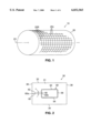
- FIG. 1 is a perspective view of a die holder having radial and circumferential reference marks in accordance with one embodiment of the present invention
- FIG. 2 is a plan view of a die having straight and angular reference marks in accordance with one embodiment of the present invention
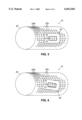
- FIG. 3 is a perspective view illustrating the die of FIG. 2 disposed on the die holder of FIG. 1 with the straight reference mark of the die aligned with the radial reference mark of the die holder;
- FIG. 4 is a perspective view illustrating the die of FIG. 2 disposed on the die holder of FIG. 1 with the angular reference mark of the die aligned with the radial reference mark of the die holder;
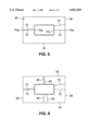
- FIG. 5 is a plan view of another embodiment of the die illustrating the reference marks extending between the sides of the die;
- FIG. 6 is a plan view of an embodiment of the die illustrating reference marks extending between the top and bottom edges and the side of the die;
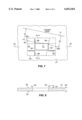
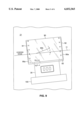
- FIG. 7 is a plan view of an embodiment of the die illustrating reference marks extending from the center of the leading edge of the pattern surface
- FIG. 8 is a cross section of the die taken along line 8--8 in FIG. 7;
- FIG. 9 is a plan view of a template for aligning the die at predetermined orientation and position on a die holder and a holding plate;
- FIG. 10 is a cross section view of the template and the die taken along line 10--10 in FIG. 9;
- FIG. 11 is a plan view of another embodiment of a die having a straight leading end and an angularly-disposed trailing end.
- a multi-use impression system 10 for forming patterns in and/or cutting sheet-like work-piece material such as paper and the like.
- the system 10 comprises a die holder 20 adapted for magnetically retaining a die plate 30 in selected positions around its outer surface 18 as generally shown in FIG. 3.
- the die holder 20 has a cylindrical shape and is mounted for rotation so that the die plate 30 engages a different material blank for each rotation of the die holder 20.
- the die holder 20 has a longitudinal axis 23 generally extending along the axis of the drive shaft 12.
- Conventional die holders will have a leading edge reference mark 11 indicating where the leading edge of the die plate 30 is to be aligned as shown for example in FIGS. 7 and 10.
- Typical impression or die plates 30 comprise inter alia perforating plates for cutting perforation slots in the material, scoring plates for forming grooves in the material, embossing plates for pressing one side of a material to form a raised pattern or impression on the opposing side of the material, and cutting plates for cutting a pattern in the material.
- the die plate 30 is a flexible sheet of metal which, as shown in FIG. 2, has a leading edge 32, a trailing edge 34 and opposing side edges 36, 38 for selectively and releasably attaching to the die holder 20.
- the die plate 30 has a flat or a slightly curved first surface 31 and a raised pattern second surface 50 having a contour corresponding to the outline of the pattern to be formed in the material blank or web.
- the pattern surface 50 has a rectangular contour to cut a rectangular window panel from an envelope blank defined by a leading pattern surface 52, a trailing pattern surface 54, and opposing side pattern surfaces 56, 58.
- the pattern surface 50 may also have other appropriate shapes and patterns known to those skilled in the art including, for example, a pattern surface adapted to cut the sides of an envelope blank
- the die plate 30 may be manufactured from any suitable flexible magnetic material including, for example, stainless steel, carbon steel or the like. Referring to FIG. 8, the thickness H2 of a cutting die 30 at the pattern surface 50 will typically be from about 0.003-0.033 inches and the thickness H1 of the plate at surface 31 will typically be from about 0.003-0.060 inches, but may vary depending upon the application. Other types of impression plates may have different dimensions depending upon the application.
- the system 10 has an alignment means for accurately aligning the die plate 30 on the die holder 20 at predetermined angular orientations either in straight-based or angular-based systems and for accurately positioning the die plate at predetermined radial and circumferential positions on the die holder.
- the alignment means comprises the die holder 20 (shown in FIGS. 1, 3-4) having a plurality of radial reference markings 20r and circumferential reference markings 20c disposed on the exterior surface which run radially and circumferentially, respectively, relative to longitudinal axis 23.
- the radial and circumferential markings 20r, 20c provide positional reference points for accurate radial and circumferential positioning of the die plate 30 at predetermined locations so that the die may accurately and repeatedly form the pattern in the successive material blanks.
- the radial and circumferential markings 20r, 20c are uniformly spaced, typically every 1/8 inch or as needed, about the entire surface of the die holder 20 to give the operator uniform reference points for accurate alignment of the die plate 30 at predetermined positions. It will be appreciated, however, that any number of radial or circumferential reference markings 20r, 20c may be used. Similarly, the radial and circumferential markings 20r, 20c may be placed anywhere on the surface of the die holder 20 such that the die plate 30 may be positioned at the predetermined position. It is preferred that the radial marks 20r be parallel to the longitudinal axis of the die holder 20 and that the circumferential marks 20c be perpendicular to the radial marks 20r for ease of manufacture.
- the die plate 30 (shown in FIGS. 2-4) has at least first and second reference markers 60, 62 which are angularly disposed relative to each other and which cooperate with one or more of the die holder reference marks 20r, 20c to properly align the die plate 30 in the predetermined orientation relative to the longitudinal axis of the die holder 20 and to accurately position the die plate 30 at the predetermined radial and circumferential positions on the die holder 20.
- the first or "straight" reference mark 60 is adapted to cooperatively align with the one of the reference marks 20r, 20c on the die holder 20 so as to properly align the die plate 30 on the die holder 20 at a predetermined orientation for straight-based systems.
- the straight reference mark 60 is aligned with the radial mark 20r to orientate the leading pattern edge 52 parallel to the longitudinal axis 23.
- the second or “angular” reference mark 62 is adapted to cooperatively align with one of the reference marks 20r, 20c on the die holder 20 so that the die plate 30 is properly aligned on the die holder 20 at a predetermined orientation and position for angular-based systems.
- FIG. 1 the first or "straight" reference mark 60 is adapted to cooperatively align with the one of the reference marks 20r, 20c on the die holder 20 so as to properly align the die plate 30 on the die holder 20 at a predetermined orientation for angular-based systems.
- the angular reference mark 62 is aligned with the radial mark 20r to angularly orientate the leading pattern edge 52 relative to the longitudinal axis 23 of the die holder 20.
- the die reference marks 60, 62 may be aligned with one of the circumferential mark 20c on the die holder 20.
- the angle ⁇ formed between the straight reference mark 60 and the angular reference mark 62 will depend on the particular system used by the operator. In cutting systems using cutting plates, for example, the angular-based systems typically require that the leading cutting surface 52 be angularly displaced about 11/2 degrees relative to the longitudinal axis 23. Thus, referring to FIG. 2, the angle ⁇ between the marks 60 and 62 will typically be 11/2 degrees to accommodate the F. L. SmithTM and Winkler and DunibierTM cutting systems. It will be appreciated however that the angle ⁇ may be varied to accommodate any other systems so as to provide the desired angular alignment.
- the reference marks 60, 62 are disposed on the die plate 30 so that the leading cutting surface 52 is maintained parallel to the longitudinal axis 23 of the die holder 20. If the cutting surface 50 has an irregular shape, the center of the leading cutting surface 52 is typically the reference point for proper alignment on the die holder 20.
- the reference marks 60, 62 on the die 30 may be raised above the die surface 31 as shown in FIG. 8 (although not as high as the pattern surface 52), recessed below the surface 31, or even a slot or holes extending through the cutting die 30. As shown in FIG. 7, it may also be desirable to have the holes for one reference mark delineated as one shape 88 such as a square and the holes for the other reference mark delineated as another shape 89, such as a circle, to assist the operator in selecting and subsequently aligning the reference marks.
- each reference mark 60, 62 requires at least two points adapted to align the die plate 30 with the reference marks 20r, 20c on the die holder 20.
- the die reference markers 60, 62 may be of any desired length. Referring to FIGS. 2-4, it will be seen that the reference marks 60, 62 extend from the left side 36 of the die plate 30 up to the left pattern surface 56 but do not actually mar the pattern surface 50, effectively presenting two reference points 60a, 60b.
- the two reference points 60a, 60b permit alignment of the die reference mark 60 and one of the die holder reference marks 20r, 20c.
- the reference marks 70, 72 extend from the left side 36 to the right side 38 of the die plate 30 and passes by, without marring, the pattern surface 50, thereby presenting four reference points 70a, 70b, 70c, 70d for easier alignment and positioning of the die plate 30.
- the reference marks 80, 82 are disposed adjacent the leading and/or trailing ends 32, 34 of the die plate 30 which permit the die plate 30 to be aligned and positioned relative to the circumferential reference marks 20c on the die holder 20.
- the presence of the reference marks 80, 82 at the leading/trailing ends 32, 34 and the reference marks 70, 72 at the sides 36, 38 permit the die plate 30 to be accurately positioned in any predetermined radial and circumferential position, respectively, on the die holder 20.
- the present invention permits the die to be relatively smaller, more compact, and less expensive to manufacture.
- a plurality of the dies 30 may be disposed on the die holder 20. It will also be appreciated that the corresponding straight reference marks 70 and 80 and the corresponding angular reference marks 72 and 82 are perpendicular to each other.
- the die plate 30 may also be utilized with conventional die holders 21 generally illustrated in FIG. 7 which have a leading edge reference mark 11 generally illustrated in FIG. 7, but not radial and circumferential reference marks as shown in FIGS. 1 and 3-4.
- the alignment means comprises the die 30 having a straight reference mark 80 adapted to properly orientate the die in straight-based systems and an angular reference mark 82 adapted to orientate the die in angular-based systems.
- the leading edge reference mark 11 is angularly orientated relative to the longitudinal axis 23 of the die holder 21.
- the die plate 30 is placed on the die holder 21 so that the angular reference mark 82 is equidistant (D1) from the die holder leading edge 11 so that the reference mark 82 and the die holder leading edge 11 are parallel to each other.
- the reference marks 80, 82 pass by without marring the center of the leading edge of the pattern.
- the endpoints of the reference marks 82a, 82b make convenient reference points for measuring distance D1.
- the reference marks 80 and 82 pass by the center of the leading pattern surface 52.
- Reference marks 84, 86, 88 may also be disposed by the side pattern surfaces 56 or the trailing pattern surface 54.
- the alignment means comprises a template 90 having reference marks and a trailing edge 93.
- the template 90 comprises straight reference marks 90a disposed along opposing sides 91, 92 and at least one angular reference mark 90b which are adapted to be aligned with the leading reference edge 11 of the die holder 21.
- the straight reference marks 90a also form a ruler.
- the trailing edge 93 provides a reference edge for the die plate 30. By aligning the reference marks (number 3 in the illustrated embodiment) with the leading edge 11 of the die holder 21, the trailing edge 93 is disposed at the proper angular orientation.
- FIGS. 9-10 show one embodiment in which the trailing edge 93 is formed as an undercut edge in the template 90.
- the system 10 may also have a holding plate 100 which is adapted to be placed adjacent to and in abutting relationship with the trailing edge 34 of the die plate 30 in order to provide additional securement of the die plate 30 and prevent the die plate 30 from sliding on the die holder 21 during rotation.
- the holding plate 100 has a flat, rectangular surface 101 which is disposed below the level of the pattern edge 50 of the die plate 30.
- the holding plate 100 is preferably manufactured from a material which is magnetically attracted to the magnetic holder 20 so as to be held thereto by magnetic attraction. This assists in preventing slippage and movement of the die plate 30 during the impressing operation.
- FIG. 11 Another embodiment of the alignment means is illustrated in FIG. 11.
- the die plate 130 has a straight reference mark delineated by the leading edge 132 and an angular reference mark delineated by the trailing edge 134.
- the trailing edge 134 forms an angle ⁇ relative to the leading edge 132.
- the reference marks 132, 134 may be aligned with the conventional die holder leading edge 11 shown in FIG. 7, the template 90 shown in FIG. 9 or the die holder reference marks 20r, 20c shown in FIG. 1.
Abstract
A multi-use die system is provided having a die holder with reference marks disposed circumferentially and radially along the longitudinal axis of the holder, and a multi-use die plate for magnetic affixation to the die holder which impresses a pattern onto a material blank. The die plate has straight and angular reference marks disposed thereon which are adapted to align with the radial and longitudinal reference marks on the die holder so as to properly align the die on the die holder at a predetermined position. In a straight rotary die system, the die is aligned such that the straight reference mark on the die is aligned with the respective corresponding radial and circumferential references on the die holder. In the angular rotary die system, the die is aligned such that the angular mark is aligned with the corresponding radial and circumferential references on the die holder.
Description
This is a divisional application of application Ser. No. 08/243,958 filed May 17, 1994 now U.S. Pat. No. 5,697,277, issued Dec. 16, 1997.
The present invention relates generally to a system for properly aligning a die plate relative to a die holder.
Impressing systems comprising die plates mounted on a die holder are utilized to process and finish predetermined patterns in sheet-like material typically found in web or blank form. Typical die plates include perforating plates, scoring plates, embossing plates, cutting plates and the like. The die plates may be magnetically attached to the die holder which brings the plate into successive contact with the web or blank which advance on a conveyor system. The die plate must be accurately positioned on the die holder at a predetermined position to accurately engage the web or blank.
U.S. Pat. No. 4,823,659 to Falasconi, for example, describes a specific embodiment of an impressing system comprising a conventional rotary panel cutting apparatus for cutting windows, notches, cavities, orifices or other patterns in relatively thin, flexible sheet-like material typically found in either sheet or web form. The cutting apparatus may be used to produce envelopes having a transparent panel or window for allowing visual inspection of the enclosure. The window envelopes are manufactured from a web of material or from previously cut blanks having a predetermined shape. A panel is subsequently cut from the blank to form the window. A transparent material may be added to cover the window. The bank may be gummed, folded, printed and packaged to form the finished envelope.
The cutting apparatus comprises a cutting tool in the form of a cutting plate or die which may be magnetically mounted on a rotary die holder which brings the cutting die into successive contact with the web and the blanks which advance on a conveyor system. The cutting die has a raised cutting surface which is adapted to engage the paper and cut a pattern in the material. The die holder, sometimes called a die cylinder or drum, is mounted for rotation on a drive shaft synchronized with the conveyor system so that the cutting die engages a different blank for each rotation of the die holder at a specific predetermined location.
In the impression system, the die plate must be accurately aligned and positioned at a predetermined position along both the radial and circumferential axis of the die holder in order to insure that the die plate accurately and repeatedly engages the web blank. In order to position the die plate on the die holder in conventional systems, the leading edge of the die plate is typically disposed along a single leading edge reference mark disposed on the die holder.
Rotary impression system apparatus typically utilize one of a "straight" or an "angular" alignment system. Envelope rotary cutting apparatus, for example, include the "angular" based rotary cutting die systems made by F. L. Smithe Company™ and the like and "straight" based cutting die system made by Winkler and Dunibier Company™ and the like. In the straight system, when the leading edge of the cutting die is positioned along the die holder leading edge, the leading cutting surface of the cutting die is typically parallel to or horizontally aligned with the longitudinal axis of the die holder and a zero degree angle is formed relative to the longitudinal axis of the die holder. In contrast, in angular systems, when the leading edge of the cutting die is positioned along the die holder leading edge, the leading cutting surface of the cutting die is angularly aligned relative to the longitudinal axis of the holder. Different cutting systems will have different angular orientations, typically from about 0 to about 15° in either direction, and preferably at a 11/2 degree.
Operators are thus required to maintain separate dies for each of the straight and the angular systems. An operator making a certain pattern will thus require two separate die plates when the impression operation is performed on both the angular and the straight systems. This has resulted in a relatively expensive duplication of inventory of die plates.
It is an object of the invention to provide an improved impression tool for impressing patterns in sheet-like material.
Another object of the invention is to provide an improved impression tool which functions in an efficient manner, is easily assembled, and is adapted for operation with different die plate systems.
It is a related object of the invention to provide an impression tool which permits the die plate to be easily and accurately positioned on the die plate holder.
It is also an object of the present invention to provide a die plate which may be utilized with either straight or angular based impression systems.
It is a specific object of the invention to provide an improved cutting tool for cutting patterns in sheet-like material.
Another object of the invention is to provide an improved cutting tool which functions in an efficient manner, is easily assembled, and is adapted for operation with different cutting dies systems.
It is a related object of the invention to provide a cutting tool which permits the cutting die to be easily and accurately positioned on the die holder.
It is also an object of the present invention to provide a cutting die which may be utilized in either straight or angular based cutting systems.
These and other features and advantages of the invention will be more readily apparent upon reading the following description of a preferred exemplified embodiment of the invention and upon reference to the accompanying drawings wherein:
FIG. 1 is a perspective view of a die holder having radial and circumferential reference marks in accordance with one embodiment of the present invention;
FIG. 2 is a plan view of a die having straight and angular reference marks in accordance with one embodiment of the present invention;
FIG. 3 is a perspective view illustrating the die of FIG. 2 disposed on the die holder of FIG. 1 with the straight reference mark of the die aligned with the radial reference mark of the die holder;
FIG. 4 is a perspective view illustrating the die of FIG. 2 disposed on the die holder of FIG. 1 with the angular reference mark of the die aligned with the radial reference mark of the die holder;
FIG. 5 is a plan view of another embodiment of the die illustrating the reference marks extending between the sides of the die;
FIG. 6 is a plan view of an embodiment of the die illustrating reference marks extending between the top and bottom edges and the side of the die;
FIG. 7 is a plan view of an embodiment of the die illustrating reference marks extending from the center of the leading edge of the pattern surface;
FIG. 8 is a cross section of the die taken along line 8--8 in FIG. 7;
FIG. 9 is a plan view of a template for aligning the die at predetermined orientation and position on a die holder and a holding plate;
FIG. 10 is a cross section view of the template and the die taken along line 10--10 in FIG. 9; and
FIG. 11 is a plan view of another embodiment of a die having a straight leading end and an angularly-disposed trailing end.
While the invention will be described and disclosed in connection with certain preferred embodiments and procedures, it is not intended to limit the invention to those specific embodiments. Rather it is intended to cover all such alternative embodiments and modifications as fall within the spirit and scope of the invention.
Referring to the drawings and more particularly to FIGS. 1-3, one embodiment of a multi-use impression system 10 is provided in accordance with the present invention for forming patterns in and/or cutting sheet-like work-piece material such as paper and the like. The system 10 comprises a die holder 20 adapted for magnetically retaining a die plate 30 in selected positions around its outer surface 18 as generally shown in FIG. 3.
Referring to FIG. 1, the die holder 20 has a cylindrical shape and is mounted for rotation so that the die plate 30 engages a different material blank for each rotation of the die holder 20. The die holder 20 has a longitudinal axis 23 generally extending along the axis of the drive shaft 12. Conventional die holders will have a leading edge reference mark 11 indicating where the leading edge of the die plate 30 is to be aligned as shown for example in FIGS. 7 and 10.
Typical impression or die plates 30 comprise inter alia perforating plates for cutting perforation slots in the material, scoring plates for forming grooves in the material, embossing plates for pressing one side of a material to form a raised pattern or impression on the opposing side of the material, and cutting plates for cutting a pattern in the material. Although the invention is described using a cutting plate in the following embodiments, it will be appreciated that the invention is adaptable to any impression plate.
The die plate 30 is a flexible sheet of metal which, as shown in FIG. 2, has a leading edge 32, a trailing edge 34 and opposing side edges 36, 38 for selectively and releasably attaching to the die holder 20. The die plate 30 has a flat or a slightly curved first surface 31 and a raised pattern second surface 50 having a contour corresponding to the outline of the pattern to be formed in the material blank or web. In the illustrated embodiment, the pattern surface 50 has a rectangular contour to cut a rectangular window panel from an envelope blank defined by a leading pattern surface 52, a trailing pattern surface 54, and opposing side pattern surfaces 56, 58. It will be appreciated that the pattern surface 50 may also have other appropriate shapes and patterns known to those skilled in the art including, for example, a pattern surface adapted to cut the sides of an envelope blank The die plate 30 may be manufactured from any suitable flexible magnetic material including, for example, stainless steel, carbon steel or the like. Referring to FIG. 8, the thickness H2 of a cutting die 30 at the pattern surface 50 will typically be from about 0.003-0.033 inches and the thickness H1 of the plate at surface 31 will typically be from about 0.003-0.060 inches, but may vary depending upon the application. Other types of impression plates may have different dimensions depending upon the application.
In accordance with certain objectives of the invention, the system 10 has an alignment means for accurately aligning the die plate 30 on the die holder 20 at predetermined angular orientations either in straight-based or angular-based systems and for accurately positioning the die plate at predetermined radial and circumferential positions on the die holder.
In one embodiment of the invention, the alignment means comprises the die holder 20 (shown in FIGS. 1, 3-4) having a plurality of radial reference markings 20r and circumferential reference markings 20c disposed on the exterior surface which run radially and circumferentially, respectively, relative to longitudinal axis 23. The radial and circumferential markings 20r, 20c provide positional reference points for accurate radial and circumferential positioning of the die plate 30 at predetermined locations so that the die may accurately and repeatedly form the pattern in the successive material blanks. In one embodiment, the radial and circumferential markings 20r, 20c are uniformly spaced, typically every 1/8 inch or as needed, about the entire surface of the die holder 20 to give the operator uniform reference points for accurate alignment of the die plate 30 at predetermined positions. It will be appreciated, however, that any number of radial or circumferential reference markings 20r, 20c may be used. Similarly, the radial and circumferential markings 20r, 20c may be placed anywhere on the surface of the die holder 20 such that the die plate 30 may be positioned at the predetermined position. It is preferred that the radial marks 20r be parallel to the longitudinal axis of the die holder 20 and that the circumferential marks 20c be perpendicular to the radial marks 20r for ease of manufacture.
The die plate 30 (shown in FIGS. 2-4) has at least first and second reference markers 60, 62 which are angularly disposed relative to each other and which cooperate with one or more of the die holder reference marks 20r, 20c to properly align the die plate 30 in the predetermined orientation relative to the longitudinal axis of the die holder 20 and to accurately position the die plate 30 at the predetermined radial and circumferential positions on the die holder 20.
In the die plate 30 illustrated in FIG. 2, the first or "straight" reference mark 60 is adapted to cooperatively align with the one of the reference marks 20r, 20c on the die holder 20 so as to properly align the die plate 30 on the die holder 20 at a predetermined orientation for straight-based systems. In FIG. 3, the straight reference mark 60 is aligned with the radial mark 20r to orientate the leading pattern edge 52 parallel to the longitudinal axis 23. Similarly, the second or "angular" reference mark 62 is adapted to cooperatively align with one of the reference marks 20r, 20c on the die holder 20 so that the die plate 30 is properly aligned on the die holder 20 at a predetermined orientation and position for angular-based systems. In FIG. 4, the angular reference mark 62 is aligned with the radial mark 20r to angularly orientate the leading pattern edge 52 relative to the longitudinal axis 23 of the die holder 20. In other embodiments, the die reference marks 60, 62 may be aligned with one of the circumferential mark 20c on the die holder 20.
The angle α formed between the straight reference mark 60 and the angular reference mark 62 will depend on the particular system used by the operator. In cutting systems using cutting plates, for example, the angular-based systems typically require that the leading cutting surface 52 be angularly displaced about 11/2 degrees relative to the longitudinal axis 23. Thus, referring to FIG. 2, the angle α between the marks 60 and 62 will typically be 11/2 degrees to accommodate the F. L. Smith™ and Winkler and Dunibier™ cutting systems. It will be appreciated however that the angle α may be varied to accommodate any other systems so as to provide the desired angular alignment.
In cutting dies 30 having the illustrated rectangular cutting surface 50, the reference marks 60, 62 are disposed on the die plate 30 so that the leading cutting surface 52 is maintained parallel to the longitudinal axis 23 of the die holder 20. If the cutting surface 50 has an irregular shape, the center of the leading cutting surface 52 is typically the reference point for proper alignment on the die holder 20.
The reference marks 60, 62 on the die 30 may be raised above the die surface 31 as shown in FIG. 8 (although not as high as the pattern surface 52), recessed below the surface 31, or even a slot or holes extending through the cutting die 30. As shown in FIG. 7, it may also be desirable to have the holes for one reference mark delineated as one shape 88 such as a square and the holes for the other reference mark delineated as another shape 89, such as a circle, to assist the operator in selecting and subsequently aligning the reference marks.
In order to accurately position and align the die plate 30 at a predetermined position and orientation on the die holder 20, each reference mark 60, 62 requires at least two points adapted to align the die plate 30 with the reference marks 20r, 20c on the die holder 20. The die reference markers 60, 62 may be of any desired length. Referring to FIGS. 2-4, it will be seen that the reference marks 60, 62 extend from the left side 36 of the die plate 30 up to the left pattern surface 56 but do not actually mar the pattern surface 50, effectively presenting two reference points 60a, 60b. The two reference points 60a, 60b permit alignment of the die reference mark 60 and one of the die holder reference marks 20r, 20c.
In the embodiment illustrated in FIG. 5, the reference marks 70, 72 extend from the left side 36 to the right side 38 of the die plate 30 and passes by, without marring, the pattern surface 50, thereby presenting four reference points 70a, 70b, 70c, 70d for easier alignment and positioning of the die plate 30.
In the embodiment illustrated in FIG. 6, the reference marks 80, 82 are disposed adjacent the leading and/or trailing ends 32, 34 of the die plate 30 which permit the die plate 30 to be aligned and positioned relative to the circumferential reference marks 20c on the die holder 20. The presence of the reference marks 80, 82 at the leading/trailing ends 32, 34 and the reference marks 70, 72 at the sides 36, 38 permit the die plate 30 to be accurately positioned in any predetermined radial and circumferential position, respectively, on the die holder 20. Thus, unlike conventional systems which require a relatively large die which spans the distance from the leading pattern edge 52 to the die holder leading edge reference mark 11, the present invention permits the die to be relatively smaller, more compact, and less expensive to manufacture. Thus, a plurality of the dies 30 may be disposed on the die holder 20. It will also be appreciated that the corresponding straight reference marks 70 and 80 and the corresponding angular reference marks 72 and 82 are perpendicular to each other.
The die plate 30 may also be utilized with conventional die holders 21 generally illustrated in FIG. 7 which have a leading edge reference mark 11 generally illustrated in FIG. 7, but not radial and circumferential reference marks as shown in FIGS. 1 and 3-4. In this embodiment, the alignment means comprises the die 30 having a straight reference mark 80 adapted to properly orientate the die in straight-based systems and an angular reference mark 82 adapted to orientate the die in angular-based systems. In FIG. 7, the leading edge reference mark 11 is angularly orientated relative to the longitudinal axis 23 of the die holder 21. The die plate 30 is placed on the die holder 21 so that the angular reference mark 82 is equidistant (D1) from the die holder leading edge 11 so that the reference mark 82 and the die holder leading edge 11 are parallel to each other. In the illustrated embodiment, the reference marks 80, 82 pass by without marring the center of the leading edge of the pattern. In FIG. 7, the endpoints of the reference marks 82a, 82b make convenient reference points for measuring distance D1. In FIG. 7, it will be appreciated that the reference marks 80 and 82 pass by the center of the leading pattern surface 52. Reference marks 84, 86, 88 may also be disposed by the side pattern surfaces 56 or the trailing pattern surface 54.
In another embodiment, the alignment means comprises a template 90 having reference marks and a trailing edge 93. In the embodiment illustrated in FIGS. 9-10, the template 90 comprises straight reference marks 90a disposed along opposing sides 91, 92 and at least one angular reference mark 90b which are adapted to be aligned with the leading reference edge 11 of the die holder 21. In the illustrated embodiment, the straight reference marks 90a also form a ruler. The trailing edge 93 provides a reference edge for the die plate 30. By aligning the reference marks (number 3 in the illustrated embodiment) with the leading edge 11 of the die holder 21, the trailing edge 93 is disposed at the proper angular orientation. Thus, when the leading edge 32 of the die plate 30 is in abutting engagement against the reference edge 93, the die plate 30 will also be orientated at the proper angular orientation. FIGS. 9-10 show one embodiment in which the trailing edge 93 is formed as an undercut edge in the template 90.
In accordance with certain objects of the invention, the system 10 may also have a holding plate 100 which is adapted to be placed adjacent to and in abutting relationship with the trailing edge 34 of the die plate 30 in order to provide additional securement of the die plate 30 and prevent the die plate 30 from sliding on the die holder 21 during rotation. The holding plate 100 has a flat, rectangular surface 101 which is disposed below the level of the pattern edge 50 of the die plate 30. The holding plate 100 is preferably manufactured from a material which is magnetically attracted to the magnetic holder 20 so as to be held thereto by magnetic attraction. This assists in preventing slippage and movement of the die plate 30 during the impressing operation.
Another embodiment of the alignment means is illustrated in FIG. 11. The die plate 130 has a straight reference mark delineated by the leading edge 132 and an angular reference mark delineated by the trailing edge 134. The trailing edge 134 forms an angle α relative to the leading edge 132. The reference marks 132, 134 may be aligned with the conventional die holder leading edge 11 shown in FIG. 7, the template 90 shown in FIG. 9 or the die holder reference marks 20r, 20c shown in FIG. 1.
Thus, it will be seen that a multi-use impression apparatus has been provided which attain the aforenoted objects. Although the structure and operation of the apparatus has been described in connection with the cutting of paper-like material, it is not intended that the invention be limited only to such operations. Various additional modifications of the described embodiments of the invention specifically illustrated and described herein will be apparent to those skilled in the art, particularly in light of the teachings of this invention. The invention may be utilized in the formation of any pattern in any thin and flexible sheet-like material, including, for example, paper, cloth or plastic materials to form envelopes, labels, sanitary napkins, window patterns and the like. It is intended that the invention cover all modifications and embodiments which fall within the spirit and scope of the invention. Thus, while preferred embodiments of the present invention have been disclosed, it will be appreciated that it is not limited thereto but may be otherwise embodied within the scope of the following claims.
Claims (30)
1. A die plate for use in at least one of impressing, cutting, scoring, and embossing a web of workpiece material, said die plate providing for magnetic retention in a selected locatable position upon a cylindrical magnetic die holder having thereupon circumferential and radial reference marks extending relative to a longitudinal axis of said die holder, said die plate comprising:
(a) a thin flexible magnetically compatible material having a first surface defined by leading, trailing and two opposing side edges wherein at least one of the edges has a first alignment mark and a second alignment mark displaced by a predefined angle other than 90° relative to the first alignment mark such that said first and second reference marks are not parallel;
(b) a second impression surface raised above said first surface adapted to contact said workpiece material to perform at least one of impressing, cutting, scoring, and embossing said workpiece material, said impression surface having at least one of a leading impression surface and a side impression surface;
(c) wherein said die plate is aligned at a predetermined first angular orientation corresponding to alignment of the first alignment mark to a selected one of said reference marks on said magnetic die holder; and
wherein said die plate is aligned at a predetermined second angular orientation corresponding to alignment of the second alignment mark to the same selected one of said reference marks on said magnetic die holder;
wherein at said first orientation at least one of said edges are aligned in a first position with the first alignment mark aligned relative to one of said circumferential and radial reference marks; and
wherein at said second orientation at least one of said edges are aligned in a second position with the first alignment mark aligned relative to one of said circumferential and radial reference marks.
2. The die plate as set forth in claim 1, further comprising a holding plate adjacent to and abutting said die plate wherein said holding plate comprises a magnetically compatible material formed into a sheet, and coupled to said magnetic rotary die holder by magnetic adhesion.
3. The die plate as set forth in claim 1, wherein said impression surface comprises means for cutting a pattern in said material.
4. The die plate as set forth in claim 1, wherein said impression surface comprises means for perforating said material.
5. The die plate as set forth in claim 1, wherein said impression surface comprises means for embossing said material.
6. The die plate as set forth in claim 5, wherein said means for embossing comprises means for engaging a first side of said material to form a pattern on a second side of said material.
7. The die plate as set forth in claim 1, wherein said first and second alignment marks are for cooperatively aligning said die plate with at least one of said reference marks on said die holder such that said first alignment mark aligns said leading impression surface of said die plate at a first location parallel to said longitudinal axis of said die holder and said second alignment mark aligns said leading impression surface of said die plate at a second location at a predetermined angle relative to said longitudinal axis of said die holder.
8. The die plate as set forth in claim 7, further comprises a third alignment mark for cooperatively aligning said die plate with said reference marks on said die holder at one of said first and second orientations.
9. The die plate as set forth in claim 8, wherein each said alignment mark comprises a line extending from said at least one opposing side edge to a point adjacent one of said leading and said side impression surfaces thereby providing two endpoints adaptable for aligning said die plate relative to said die holder reference marks.
10. The die plate as set forth in claim 7, wherein said angle formed by said first and second alignment marks is between zero and about fifteen degrees.
11. The die plate as set forth in claim 10, wherein said angle formed by said first and second alignment marks is approximately 1.50 degrees.
12. The die plate as set forth in claim 7, wherein said alignment marks comprise a plurality of shapes for differentiating one said alignment mark from another said alignment mark.
13. The die plate as set forth in claim 12, wherein said plurality of shapes are comprised of apertures formed in said die plate.
14. A die plate capable of magnetic adhesion to a cylindrical magnetic die plate holder wherein said magnetic die plate holder has reference marks on an outer surface running circumferentially and radially relative to a longitudinal axis of said magnetic die plate holder, said die plate comprising:
a flexible thin sheet of magnetic material which provides for direct contact magnetic adhesion and retention of said die plate to said outer surface of said die plate holder, said sheet of magnetic material having a sheet surface defined by a leading edge, a trailing edge, and two opposing side edges;
an impression surface raised above said sheet surface, said impression surface comprising a leading impression surface;
said die plate further comprising first and second alignment marks on at least one of the edges of said die plate wherein said first and second alignment marks are angularly related by a predefined angle other than 90° when aligned relative to said reference marks at predetermined orientations thereto and wherein said first and second alignment marks are not parallel.
15. A die plate according to claim 14, wherein a first one of the predetermined orientations, corresponding to alignment of the first alignment mark with the respective associated reference mark, said leading impression surface is aligned at a first predefined angle relative to said longitudinal axis of said magnetic die plate holder; and
wherein at another one of the predetermined orientations, corresponding to alignment of the first alignment mark with the respective associated reference mark, said leading impression surface is aligned at a second predefined angle relative to said longitudinal axis of said magnetic die pate holder.
16. A die plate as set forth in claim 14, wherein each alignment mark comprises a line extending from one of the side edges of the die plate to a point adjacent the impression surface thereby forming two endpoints capable of aligning the die plate relative to the die plate holder reference marks.
17. A die plate as set forth in claim 14, wherein each alignment mark comprises a line extending between two of the edges of the die plate forming at least two endpoints capable of aligning the die plate relative to the die plate holder reference marks.
18. A die plate as set forth in claim 14, wherein each alignment mark comprises a line extending between two edges of the die plate and past the impression surface forming at least four endpoints capable of aligning the die plate relative to the die plate holder reference marks.
19. A die plate as set forth in claim 14, wherein the first and second alignment marks each include a plurality of holes, said holes of said first alignment marks being of a different shape than the holes of said second alignment mark.
20. A die plate as set forth in claim 14, wherein the angle formed between the first and second alignment marks is from 0 and about 15 degrees.
21. A die plate as set forth in claim 14, wherein the angle formed between the first and second alignment marks is approximately 11/2 degrees.
22. A die plate as set forth in claim 14, wherein the trailing and leading edges and one of the side edges each has corresponding first and second angularly related alignment marks to cooperatively align with corresponding one of the reference marks on the die plate holder such that the first alignment mark provides fob aligning the leading impression surface parallel to the longitudinal axis, and the second alignment mark provides for aligning the leading impression surface at a predetermined angle relative to the longitudinal axis.
23. A die plate as set forth in claim 22 wherein an angular displacement between the first and second alignment marks is identical for each one of said trailing and leading edges and the at least one of the side edges of said die plate.
24. A die plate as set forth in claim 14, wherein each alignment mark comprises a line extending from one of the trailing and leading edges of the die plate to a point adjacent the impression surface of said die plate forming two endpoints capable of aligning the die plate relative to the die plate holder reference marks.
25. A die plate as set forth in claim 24, comprises a template having opposing sides and a trailing end, said die plate holder adapted to have a leading edge reference mark, the sides having alignment marks adapted to cooperatively align with a leading edge reference mark, and the template trailing end having a predetermined angular orientation relative to the opposing sides such that the leading impression surface is aligned in a predetermined angular orientation relative to the leading edge reference mark when the leading edge of the die is abutted against the trailing edge of the template.
26. A die plate as set forth in claim 25, wherein the trailing end is perpendicular to the leading edge reference mark so that the leading impression surface is parallel to the leading edge reference mark.
27. A die plate as set forth in claim 25, wherein the trailing end is angularly displaced relative to the leading edge reference mark so that the leading impression surface is angularly displaced relative to the leading edge reference mark.
28. A die plate as set forth in claim 27, wherein the trailing end is angularly displaced relative to the leading edge reference mark by approximately 11/2 degrees so that the leading impression surface is angularly displaced relative to the leading edge reference mark.
29. A die plate for impressing patterns in materials, said die plate capable of magnetic adhesion to a cylindrical magnetic rotary die holder, said magnetic rotary die holder comprising reference marks running circumferentially and radially relative to a longitudinal axis of said holder, at least one of said reference marks serving as a leading edge reference for said die plate, said die plate comprising:
a flexible magnetically compatible material formed into a sheet for the removable non-destructive and non-invasive positioning and adhesion of said die plate with said magnetic rotary die holder via the magnetic action of said rotary magnetic holder, said material formed into a sheet comprising a sheet surface defined by leading, trailing and opposing side edges;
an impression surface raised above said sheet surface for impressing a pattern with said material, said impression surface comprising at least one of a leading impression surface and a side impression surface;
said die plate further comprising an alignment means for selectively aligning said die plate at a predetermined orientation with said rotary magnetic holder, said alignment means comprising a template having opposing sides and a trailing end, at least one of said opposing sides having first and second alignment marks for cooperatively aligning said template with said leading edge reference of said magnetic rotary die holder wherein said first and second alignment marks are angularly related by a predefined angle other than 90° when aligned relative to said reference marks at predetermined orientations thereto and wherein said first and second alignment marks are not parallel; and
said trailing end of said template capable of having an angular orientation relative to said opposing sides such that said leading impression surface is angularly oriented relative to said leading edge reference mark when said leading edge of said die abuts said trailing end of said template.
30. The die plate set forth in claim 29, wherein said trailing end of said template is angularly disposed relative to said leading edge reference mark of said magnetic rotary die holder such that said leading impression surface is angularly disposed relative to said leading edge reference mark.
Priority Applications (1)
| Application Number | Priority Date | Filing Date | Title |
|---|---|---|---|
| US08/876,875 US6032565A (en) | 1994-05-17 | 1997-06-16 | Multi-use rotary die plate system |
Applications Claiming Priority (2)
| Application Number | Priority Date | Filing Date | Title |
|---|---|---|---|
| US08/243,958 US5697277A (en) | 1994-05-17 | 1994-05-17 | Multi use rotary die plate system |
| US08/876,875 US6032565A (en) | 1994-05-17 | 1997-06-16 | Multi-use rotary die plate system |
Related Parent Applications (1)
| Application Number | Title | Priority Date | Filing Date |
|---|---|---|---|
| US08/243,958 Division US5697277A (en) | 1994-05-17 | 1994-05-17 | Multi use rotary die plate system |
Publications (1)
| Publication Number | Publication Date |
|---|---|
| US6032565A true US6032565A (en) | 2000-03-07 |
Family
ID=22920799
Family Applications (2)
| Application Number | Title | Priority Date | Filing Date |
|---|---|---|---|
| US08/243,958 Expired - Fee Related US5697277A (en) | 1994-05-17 | 1994-05-17 | Multi use rotary die plate system |
| US08/876,875 Expired - Fee Related US6032565A (en) | 1994-05-17 | 1997-06-16 | Multi-use rotary die plate system |
Family Applications Before (1)
| Application Number | Title | Priority Date | Filing Date |
|---|---|---|---|
| US08/243,958 Expired - Fee Related US5697277A (en) | 1994-05-17 | 1994-05-17 | Multi use rotary die plate system |
Country Status (4)
| Country | Link |
|---|---|
| US (2) | US5697277A (en) |
| EP (1) | EP0805740B1 (en) |
| DE (1) | DE69521720T2 (en) |
| WO (1) | WO1995031316A1 (en) |
Cited By (14)
| Publication number | Priority date | Publication date | Assignee | Title |
|---|---|---|---|---|
| US20030141020A1 (en) * | 2002-01-16 | 2003-07-31 | Bernd Hoffmann | Device for automatically aligning cord tape, which is to be unwound |
| US6793752B2 (en) | 2001-09-21 | 2004-09-21 | The Goodyear Tire & Rubber Company | Precision longitudinal registration of tire building drum to automated tire building system work station |
| US20050079969A1 (en) * | 2002-02-13 | 2005-04-14 | Stefan Jornborn | Machine for punching blanks out of a web of corrugated cardboard and for forming folding lines in said blanks |
| US20090104570A1 (en) * | 2004-02-03 | 2009-04-23 | Spellbinders Paper Arts Company, Llc | Apertured media embellishing template and system and method using same |
| US20100224665A1 (en) * | 2009-03-09 | 2010-09-09 | Illinois Tool Works Inc. | Thermally isolated liquid supply for web moistening |
| US20100224702A1 (en) * | 2009-03-09 | 2010-09-09 | Illinois Tool Works Inc. | Pneumatic atomization nozzle for web moistening |
| US20100224703A1 (en) * | 2009-03-09 | 2010-09-09 | Illinois Tool Works Inc. | Pneumatic Atomization Nozzle for Web Moistening |
| US20100224122A1 (en) * | 2009-03-09 | 2010-09-09 | Illinois Tool Works Inc. | Low pressure regulation for web moistening systems |
| US20110011290A1 (en) * | 2009-07-20 | 2011-01-20 | Quickutz, Inc. | Systems and methods applying a design on a medium |
| US20110082020A1 (en) * | 2009-10-05 | 2011-04-07 | Lai Chu Tsai | Die for embossing and cutting |
| US20110079129A1 (en) * | 2008-05-29 | 2011-04-07 | Siegfried Fuchs | Variable window position in flex die cutter |
| US20110210111A1 (en) * | 2008-07-01 | 2011-09-01 | Masayuki Izume | Manufacturing device for machine plate for printer |
| EP2546037A1 (en) * | 2011-07-15 | 2013-01-16 | Ellison Educational Equipment, Inc. | Chemical-etched die having improved registration means |
| US10434676B2 (en) * | 2017-08-02 | 2019-10-08 | Heidelberger Druckmaschinen Ag | Rotary die-cutter for cutting a piece of material out of a printing material |
Families Citing this family (12)
| Publication number | Priority date | Publication date | Assignee | Title |
|---|---|---|---|---|
| USRE38033E1 (en) * | 1993-12-22 | 2003-03-18 | Best Cutting Die Company | Panel cutting apparatus |
| US5697277A (en) | 1994-05-17 | 1997-12-16 | Best Cutting Die Company | Multi use rotary die plate system |
| US6026725A (en) * | 1995-04-10 | 2000-02-22 | Best Cutting Die Company | Panel cutting apparatus with waste repellant die structure |
| US6119570A (en) * | 1997-06-03 | 2000-09-19 | Best Cutting Die Company | Panel cutting apparatus with universal die holder |
| JPH11156796A (en) * | 1997-11-25 | 1999-06-15 | Isowa Corp | Punching method for sheet material and device thereof |
| DE29921967U1 (en) * | 1999-06-04 | 2000-03-23 | Winkler & Duennebier Ag | Rotatable knife roller |
| FR2795988B1 (en) * | 1999-07-09 | 2002-01-18 | Komori Chambon | DEVICE FOR POSITIONING A PLATE ON A MAGNETIC FIXING CYLINDER |
| US6779426B1 (en) | 1999-12-21 | 2004-08-24 | Atlas Die Llc | Die rule retention device and retaining board incorporating same |
| US7000522B2 (en) * | 2003-12-08 | 2006-02-21 | Eagle Rotary Systems, Inc. | Rotary cutting tool with die plate position adjustment |
| SE529998C2 (en) * | 2005-04-07 | 2008-02-05 | Sandvik Intellectual Property | A support roll drum and a support roll unit for a rotatable cutting device |
| DE102009033575B4 (en) * | 2009-07-16 | 2011-07-21 | Winkler+Dünnebier AG, 56564 | Foil knife with suction chamber |
| WO2018067916A1 (en) * | 2016-10-07 | 2018-04-12 | Reed Machinery, Inc. | Cylindrical tool matching system |
Citations (111)
| Publication number | Priority date | Publication date | Assignee | Title |
|---|---|---|---|---|
| US32128A (en) * | 1861-04-23 | Improvement in cultivators | ||
| US642220A (en) * | 1899-04-04 | 1900-01-30 | Thomas L Green | Machine for cutting and shaping crackers or other plastic materials. |
| US884218A (en) * | 1907-05-22 | 1908-04-07 | George Schwarz | Cutting-stick. |
| US1168767A (en) * | 1915-06-05 | 1916-01-18 | Christian Unruh | Leather-cutter. |
| US1618191A (en) * | 1926-02-17 | 1927-02-22 | Hemberger Peter | Perforating attachment for printing presses |
| US1746048A (en) * | 1923-10-17 | 1930-02-04 | Smithe Machine Co Inc F L | Cutting mechanism |
| US1766244A (en) * | 1928-06-04 | 1930-06-24 | Guyton & Cumfer Mfg Co | Cutting cylinder |
| US1777285A (en) * | 1929-04-11 | 1930-10-07 | Rotary Carton Machine Company | Cylinder for forming cartons, etc. |
| US1927728A (en) * | 1929-07-01 | 1933-09-19 | Wolff Fritz | Form cylinder for offset-printing machines |
| US2055295A (en) * | 1933-09-01 | 1936-09-22 | United Autographic Register Co | Apparatus for attaching printing plates to a cylinder |
| US2277405A (en) * | 1938-09-09 | 1942-03-24 | Kenneth G Mckiernan | Register method and apparatus |
| US2299650A (en) * | 1940-04-23 | 1942-10-20 | Interchem Corp | Rotary cutting and scoring mechanism |
| US2386147A (en) * | 1944-08-16 | 1945-10-02 | Harlow M Russell | Method and machine for punching out articles from strips |
| US2791276A (en) * | 1954-09-02 | 1957-05-07 | Gen Motors Corp | Cloth cutting machine |
| DE1016112B (en) | 1955-09-03 | 1957-09-19 | Picard Fa Carl Aug | Cutting plate with angled clamping edge |
| US2837025A (en) * | 1956-05-08 | 1958-06-03 | American Can Co | Clamping and tensioning device |
| US2898854A (en) * | 1957-04-09 | 1959-08-11 | Earl A Crawford | Printing plate and cylinder |
| US3008366A (en) * | 1956-01-06 | 1961-11-14 | Hudson Pulp & Paper Corp | Paper perforating mechanism |
| US3032152A (en) * | 1959-11-06 | 1962-05-01 | Titsler Wayne | Locking device for insertible cutting blade |
| US3106121A (en) * | 1959-05-19 | 1963-10-08 | Smithe Machine Co Inc F L | Rotary panel cutter |
| US3128681A (en) * | 1961-10-25 | 1964-04-14 | Somerville Ind Ltd | Double die-cutting |
| US3172321A (en) * | 1961-09-25 | 1965-03-09 | Berkley Machine Co | Adjustable anvil for cutting window apertures and like openings in blanks |
| US3190194A (en) * | 1960-08-06 | 1965-06-22 | Kirby S Engineers Ltd | Apparatus for creasing and/or cutting cardboard and analogous flexible sheet material |
| US3198093A (en) * | 1963-01-28 | 1965-08-03 | Kirby S Engineers Ltd | Apparatus for creasing and/or cutting cardboard and analogous flexible sheet material |
| US3209630A (en) * | 1961-12-22 | 1965-10-05 | Ibm | Rotary punching device |
| US3244335A (en) * | 1964-01-14 | 1966-04-05 | American Can Co | Method for forming severance lines |
| US3257885A (en) * | 1964-06-19 | 1966-06-28 | Smithe Machine Co Inc F L | Rotary panel cutter |
| US3270602A (en) * | 1964-01-28 | 1966-09-06 | Kirby S Engincers Ltd | Apparatus for cutting cardboard and analogous flexible material |
| CA743783A (en) | 1966-10-04 | Kirby Kenneth | Method of and apparatus for creasing and/or cutting cardboard and analogous flexible sheet material | |
| US3289513A (en) * | 1964-09-01 | 1966-12-06 | Ibm | Rotary cutting apparatus |
| US3460443A (en) * | 1965-09-20 | 1969-08-12 | Harris Intertype Corp | Apparatus for operating on sheet material |
| US3522754A (en) * | 1967-08-14 | 1970-08-04 | Centenary Central | Reinforced freewheeling resilient cover for rotary die-cutting anvil |
| US3523474A (en) * | 1968-04-15 | 1970-08-11 | Phillips Petroleum Co | Precision trimming of thermoformed parts |
| US3527127A (en) * | 1967-09-12 | 1970-09-08 | Smithe Machine Co Inc F L | Method of shear cutting envelope blanks |
| US3530794A (en) * | 1967-02-28 | 1970-09-29 | Gerhard Ritzerfeld | Magnetic printing arrangement |
| US3533355A (en) * | 1967-02-13 | 1970-10-13 | Nat Electrotype Co Inc | Printing plate saddle |
| US3578761A (en) * | 1968-09-12 | 1971-05-18 | Harris Intertype Corp | Severing apparatus |
| GB1235372A (en) | 1968-05-20 | 1971-06-16 | De La Rue Giori Sa | Apparatus for perforating sheet material and process for making such apparatus |
| US3602079A (en) * | 1969-06-12 | 1971-08-31 | Ernest G Carlson | Universal die set |
| US3602970A (en) * | 1969-04-14 | 1971-09-07 | Ward Turner Machinery Co | Latch bar assembly for replaceable cover |
| US3618438A (en) * | 1968-11-06 | 1971-11-09 | Walter A Simson | Cutting |
| US3668752A (en) * | 1970-09-02 | 1972-06-13 | Dayco Corp | Coating roller and method of manufacture |
| US3670646A (en) * | 1970-10-09 | 1972-06-20 | Grace W R & Co | Magnetically securable printing plate |
| US3709077A (en) * | 1971-03-01 | 1973-01-09 | Bretting C Mfg Co Inc | Cut-off device |
| US3730092A (en) * | 1971-03-05 | 1973-05-01 | Grace W R & Co | Magnetic sheet for impression cylinder |
| GB1322090A (en) | 1971-12-31 | 1973-07-04 | Schuchardt R | Cutting apparatus and method of making such tools |
| US3744384A (en) * | 1970-02-21 | 1973-07-10 | Masson Scott Thrissell Eng Ltd | Rollers for cutting,creasing,perforating or embossing sheet materials |
| US3752042A (en) * | 1971-10-06 | 1973-08-14 | Castille Cutting Dies Inc | Adjustable die plate |
| US3789715A (en) * | 1972-01-04 | 1974-02-05 | R Schuchardt | Rotary cutting apparatus |
| US3797351A (en) * | 1973-03-07 | 1974-03-19 | W Jones | Mounting system for envelope-die holders |
| US3805657A (en) * | 1971-12-28 | 1974-04-23 | Container Graphics Corp | Steel rule rotary die and method of making same |
| US3810055A (en) * | 1973-05-21 | 1974-05-07 | T Wright | Magnetic holding device |
| US3823633A (en) * | 1972-06-05 | 1974-07-16 | Consolidated Educational Publi | Self-adjusting plural blade cutting roller with cushioned anvil roller |
| US3824926A (en) * | 1972-08-18 | 1974-07-23 | Yamauchi Rubber Ind Co Inc | Printing magnetic saddle |
| US3824927A (en) * | 1971-01-29 | 1974-07-23 | Ruralist Press Inc | Laminated magnetic printing roll assembly |
| US3850059A (en) * | 1973-01-08 | 1974-11-26 | Chempar Corp | Die and method for cutting labels and the like |
| US3886825A (en) * | 1973-08-10 | 1975-06-03 | Ichiro Tanaka | Method for mechanically cutting flanges from preshaped steel construction members |
| US3898899A (en) * | 1973-08-21 | 1975-08-12 | Maryland Cup Corp | Method of making package liners having starburst patterns cut therethrough |
| US3965786A (en) * | 1974-07-16 | 1976-06-29 | Moore Business Forms, Inc. | Rotary die cutter |
| US3975976A (en) * | 1975-11-03 | 1976-08-24 | Prentice Thomas H | Cutting apparatus with rotatable anvil |
| US3977283A (en) * | 1975-06-25 | 1976-08-31 | F. L. Smithe Machine Company, Inc. | Rotary panel cutter for cutting openings in a web |
| US4004479A (en) * | 1975-02-05 | 1977-01-25 | Bodnar Ernest R | Scrap chopper |
| US4020724A (en) * | 1975-02-06 | 1977-05-03 | Quinlan Albert J | Rotary cutting die |
| US4127265A (en) * | 1976-05-13 | 1978-11-28 | Heidelberger Druckmaschinen Ag | Sheet sensing device in a rotary printing press |
| DE2852521A1 (en) | 1977-12-15 | 1979-06-21 | Chesnut Eng | FASTENING ARRANGEMENT FOR A DIE SHEET TO BE CLAMPED ON A ROLLER |
| US4191076A (en) * | 1978-10-23 | 1980-03-04 | Dayco Corporation | Rotary anvil construction |
| FR2435331A1 (en) | 1978-09-08 | 1980-04-04 | Kadner Max | Demountable cutting ring for roller punch - is L=section flexible metal sheet fixed by countersunk bolts through horizontal leg |
| US4226150A (en) * | 1978-08-15 | 1980-10-07 | Avery International Corporation | Deflectable bearer roll |
| US4233873A (en) * | 1978-11-06 | 1980-11-18 | Hewlett-Packard Company | Permanent magnetic hold down for steel rule dies |
| US4237786A (en) * | 1978-10-16 | 1980-12-09 | Bunting Magnetics Company | Split-shell magnetic cylinder |
| US4270910A (en) * | 1977-07-20 | 1981-06-02 | Fritz Himmelsbach | Apparatus for separating portions of flat material cut-out from a web or sheet |
| US4289492A (en) * | 1980-01-09 | 1981-09-15 | Container Graphics Corporation | Creasing rule |
| US4402265A (en) * | 1978-11-16 | 1983-09-06 | Beach Manufacturing Corporation | Magnetic printing saddle |
| US4450740A (en) * | 1980-10-20 | 1984-05-29 | Westvaco Corporation | Rotary envelope cutting apparatus |
| US4537588A (en) * | 1983-01-22 | 1985-08-27 | Winkler & Dunnerbier Maschinenfabrik Und Eisengiesserei Gmbh & Co. Kg. | Punch device for making window cut-outs |
| US4549454A (en) * | 1983-08-22 | 1985-10-29 | Koyo Jidoki Co., Ltd. | Method for cutting and supplying labels of various shapes |
| US4553461A (en) * | 1982-10-12 | 1985-11-19 | Magna-Graphics Corporation | Rotary web processing apparatus |
| US4558620A (en) * | 1984-10-05 | 1985-12-17 | Wallis Bernard J | Punch retainer |
| USRE32128E (en) | 1979-06-23 | 1986-04-29 | Winkler & Dunnebier Maschinenfabrik Und Eisengiesserei Gmbh & Co. Kg | Transport apparatus for transporting flexible sheet-like articles |
| US4625928A (en) * | 1984-05-14 | 1986-12-02 | R. R. Donnelley & Sons Company | Method of magnetic cylinder assembly |
| US4645484A (en) * | 1984-11-05 | 1987-02-24 | Tetra Pak International Ab | Method for thinning regions of packing material to facilitate package assemblage |
| US4671152A (en) * | 1984-05-11 | 1987-06-09 | Winkler & Duennebier Maschinenfabrik Und Eisengiesserei Gmbh & Co Kg | Apparatus for cutting out windows in envelopes |
| DE3544358A1 (en) | 1985-12-14 | 1987-06-19 | Marbach Gmbh Karl | Device for clamping punching sheets |
| US4676161A (en) * | 1984-05-14 | 1987-06-30 | R. R. Donnelley & Sons Company | Magnetic cylinders with image plate or blanket for offset printing |
| US4726804A (en) * | 1986-04-28 | 1988-02-23 | Wesley Business Forms | Method and apparatus for fabricating continuous envelopes |
| US4742769A (en) * | 1985-11-15 | 1988-05-10 | M.A.N. Roland Druckmaschinen Aktiengesellschaft | Printing cylinder and axial groove filler combination |
| US4744297A (en) * | 1985-09-17 | 1988-05-17 | The Ward Machinery Company | Mounting printing plates |
| US4770078A (en) * | 1986-03-13 | 1988-09-13 | Jean Gautier | Roll-type cutting/scoring apparatus |
| US4809609A (en) * | 1984-09-19 | 1989-03-07 | Sakata Shokai, Ltd. | Method of directly mounting a printing plate on plate cylinder and the plate cylinder and register pins used in said method |
| US4823659A (en) * | 1986-11-03 | 1989-04-25 | Rofalex International Inc. | Holder for a panel cutting plate |
| US4823697A (en) * | 1988-02-25 | 1989-04-25 | Am International Incorporated | Magnetic plate cylinder |
| US4831930A (en) * | 1988-02-01 | 1989-05-23 | Integrated Design Corp. | Magnetic cylinder |
| US4842485A (en) * | 1988-02-10 | 1989-06-27 | Westinghouse Electric Corp. | Balanced turbine rotor and method for making the same |
| US4878407A (en) * | 1986-05-01 | 1989-11-07 | The Ward Machinery Company | Vacuum die mount |
| US4920843A (en) * | 1989-02-06 | 1990-05-01 | Stroemberg Sven A R | Device for retaining knife blade for cutting a paper web |
| US4920630A (en) * | 1988-02-01 | 1990-05-01 | Integrated Design Corp. | Method of making parts for a magnetic cylinder |
| US4982639A (en) * | 1988-10-31 | 1991-01-08 | Robud Company | Die cutting anvil system |
| US5003854A (en) * | 1988-02-24 | 1991-04-02 | Siemens Aktiengesellschaft | Device for fastening a die on a tool carrier cylinder of a rotary machine |
| US5005816A (en) * | 1988-06-13 | 1991-04-09 | Winkler & Dunnebier Maschinenfabrik Und Eisengiesserei Kg | Interfolder device with dynamic pressure section connected at the outlet side of the folding rollers |
| US5074180A (en) * | 1989-08-18 | 1991-12-24 | Ringspann Gmbh | Clamping system for clamping a cutter roller in axially shiftable position on a shaft |
| US5095830A (en) * | 1990-08-24 | 1992-03-17 | Atlas Die, Inc. | Means for mounting an adjustable embossing die |
| US5109741A (en) * | 1990-01-03 | 1992-05-05 | Winkler & Duennebier Maschinenfabrik Und Eisengiesserei Kg | Knife roller |
| US5119707A (en) * | 1988-12-05 | 1992-06-09 | Green Bay Engineering And Technical Service, Ltd. | Clamp bar for machine roll |
| US5138923A (en) * | 1988-11-18 | 1992-08-18 | Atlas Die, Inc. | Rotary die cutter |
| US5186108A (en) * | 1990-12-06 | 1993-02-16 | Koenig & Bauer Aktiengesellschaft | Axially adjustable register pin |
| US5211096A (en) * | 1990-12-13 | 1993-05-18 | Tamarack Products, Inc. | Apparatus for cutting |
| US5230271A (en) * | 1990-02-28 | 1993-07-27 | Scm Container Machinery Limited | Rotary die cutting apparatus |
| US5373758A (en) | 1989-02-28 | 1994-12-20 | Gerhardt; Joergen | Device for punching sheet-type material, in particular label material |
| US5555786A (en) | 1993-01-22 | 1996-09-17 | Magnaflex Systems Limited | Rotary press cutters |
| US5570620A (en) | 1993-12-22 | 1996-11-05 | Best Cutting Die Company | Panel cutting apparatus |
| US5697277A (en) | 1994-05-17 | 1997-12-16 | Best Cutting Die Company | Multi use rotary die plate system |
Family Cites Families (1)
| Publication number | Priority date | Publication date | Assignee | Title |
|---|---|---|---|---|
| US2859532A (en) * | 1954-11-19 | 1958-11-11 | Robert E Fogg | Method and apparatus for lineup and register of printing plates |
-
1994
- 1994-05-17 US US08/243,958 patent/US5697277A/en not_active Expired - Fee Related
-
1995
- 1995-05-17 EP EP95919224A patent/EP0805740B1/en not_active Expired - Lifetime
- 1995-05-17 DE DE69521720T patent/DE69521720T2/en not_active Expired - Fee Related
- 1995-05-17 WO PCT/US1995/006153 patent/WO1995031316A1/en active IP Right Grant
-
1997
- 1997-06-16 US US08/876,875 patent/US6032565A/en not_active Expired - Fee Related
Patent Citations (113)
| Publication number | Priority date | Publication date | Assignee | Title |
|---|---|---|---|---|
| US32128A (en) * | 1861-04-23 | Improvement in cultivators | ||
| CA743783A (en) | 1966-10-04 | Kirby Kenneth | Method of and apparatus for creasing and/or cutting cardboard and analogous flexible sheet material | |
| US642220A (en) * | 1899-04-04 | 1900-01-30 | Thomas L Green | Machine for cutting and shaping crackers or other plastic materials. |
| US884218A (en) * | 1907-05-22 | 1908-04-07 | George Schwarz | Cutting-stick. |
| US1168767A (en) * | 1915-06-05 | 1916-01-18 | Christian Unruh | Leather-cutter. |
| US1746048A (en) * | 1923-10-17 | 1930-02-04 | Smithe Machine Co Inc F L | Cutting mechanism |
| US1618191A (en) * | 1926-02-17 | 1927-02-22 | Hemberger Peter | Perforating attachment for printing presses |
| US1766244A (en) * | 1928-06-04 | 1930-06-24 | Guyton & Cumfer Mfg Co | Cutting cylinder |
| US1777285A (en) * | 1929-04-11 | 1930-10-07 | Rotary Carton Machine Company | Cylinder for forming cartons, etc. |
| US1927728A (en) * | 1929-07-01 | 1933-09-19 | Wolff Fritz | Form cylinder for offset-printing machines |
| US2055295A (en) * | 1933-09-01 | 1936-09-22 | United Autographic Register Co | Apparatus for attaching printing plates to a cylinder |
| US2277405A (en) * | 1938-09-09 | 1942-03-24 | Kenneth G Mckiernan | Register method and apparatus |
| US2299650A (en) * | 1940-04-23 | 1942-10-20 | Interchem Corp | Rotary cutting and scoring mechanism |
| US2386147A (en) * | 1944-08-16 | 1945-10-02 | Harlow M Russell | Method and machine for punching out articles from strips |
| US2791276A (en) * | 1954-09-02 | 1957-05-07 | Gen Motors Corp | Cloth cutting machine |
| DE1016112B (en) | 1955-09-03 | 1957-09-19 | Picard Fa Carl Aug | Cutting plate with angled clamping edge |
| US3008366A (en) * | 1956-01-06 | 1961-11-14 | Hudson Pulp & Paper Corp | Paper perforating mechanism |
| US2837025A (en) * | 1956-05-08 | 1958-06-03 | American Can Co | Clamping and tensioning device |
| US2898854A (en) * | 1957-04-09 | 1959-08-11 | Earl A Crawford | Printing plate and cylinder |
| US3106121A (en) * | 1959-05-19 | 1963-10-08 | Smithe Machine Co Inc F L | Rotary panel cutter |
| US3032152A (en) * | 1959-11-06 | 1962-05-01 | Titsler Wayne | Locking device for insertible cutting blade |
| US3190194A (en) * | 1960-08-06 | 1965-06-22 | Kirby S Engineers Ltd | Apparatus for creasing and/or cutting cardboard and analogous flexible sheet material |
| US3172321A (en) * | 1961-09-25 | 1965-03-09 | Berkley Machine Co | Adjustable anvil for cutting window apertures and like openings in blanks |
| US3128681A (en) * | 1961-10-25 | 1964-04-14 | Somerville Ind Ltd | Double die-cutting |
| US3209630A (en) * | 1961-12-22 | 1965-10-05 | Ibm | Rotary punching device |
| US3198093A (en) * | 1963-01-28 | 1965-08-03 | Kirby S Engineers Ltd | Apparatus for creasing and/or cutting cardboard and analogous flexible sheet material |
| US3244335A (en) * | 1964-01-14 | 1966-04-05 | American Can Co | Method for forming severance lines |
| US3270602A (en) * | 1964-01-28 | 1966-09-06 | Kirby S Engincers Ltd | Apparatus for cutting cardboard and analogous flexible material |
| US3257885A (en) * | 1964-06-19 | 1966-06-28 | Smithe Machine Co Inc F L | Rotary panel cutter |
| US3289513A (en) * | 1964-09-01 | 1966-12-06 | Ibm | Rotary cutting apparatus |
| US3460443A (en) * | 1965-09-20 | 1969-08-12 | Harris Intertype Corp | Apparatus for operating on sheet material |
| US3533355A (en) * | 1967-02-13 | 1970-10-13 | Nat Electrotype Co Inc | Printing plate saddle |
| US3530794A (en) * | 1967-02-28 | 1970-09-29 | Gerhard Ritzerfeld | Magnetic printing arrangement |
| US3522754A (en) * | 1967-08-14 | 1970-08-04 | Centenary Central | Reinforced freewheeling resilient cover for rotary die-cutting anvil |
| US3527127A (en) * | 1967-09-12 | 1970-09-08 | Smithe Machine Co Inc F L | Method of shear cutting envelope blanks |
| US3523474A (en) * | 1968-04-15 | 1970-08-11 | Phillips Petroleum Co | Precision trimming of thermoformed parts |
| GB1235372A (en) | 1968-05-20 | 1971-06-16 | De La Rue Giori Sa | Apparatus for perforating sheet material and process for making such apparatus |
| US3578761A (en) * | 1968-09-12 | 1971-05-18 | Harris Intertype Corp | Severing apparatus |
| US3618438A (en) * | 1968-11-06 | 1971-11-09 | Walter A Simson | Cutting |
| US3602970A (en) * | 1969-04-14 | 1971-09-07 | Ward Turner Machinery Co | Latch bar assembly for replaceable cover |
| US3602079A (en) * | 1969-06-12 | 1971-08-31 | Ernest G Carlson | Universal die set |
| US3744384A (en) * | 1970-02-21 | 1973-07-10 | Masson Scott Thrissell Eng Ltd | Rollers for cutting,creasing,perforating or embossing sheet materials |
| US3668752A (en) * | 1970-09-02 | 1972-06-13 | Dayco Corp | Coating roller and method of manufacture |
| US3670646A (en) * | 1970-10-09 | 1972-06-20 | Grace W R & Co | Magnetically securable printing plate |
| US3824927A (en) * | 1971-01-29 | 1974-07-23 | Ruralist Press Inc | Laminated magnetic printing roll assembly |
| US3709077A (en) * | 1971-03-01 | 1973-01-09 | Bretting C Mfg Co Inc | Cut-off device |
| US3730092A (en) * | 1971-03-05 | 1973-05-01 | Grace W R & Co | Magnetic sheet for impression cylinder |
| US3752042A (en) * | 1971-10-06 | 1973-08-14 | Castille Cutting Dies Inc | Adjustable die plate |
| US3805657A (en) * | 1971-12-28 | 1974-04-23 | Container Graphics Corp | Steel rule rotary die and method of making same |
| GB1322090A (en) | 1971-12-31 | 1973-07-04 | Schuchardt R | Cutting apparatus and method of making such tools |
| US3789715A (en) * | 1972-01-04 | 1974-02-05 | R Schuchardt | Rotary cutting apparatus |
| US3823633A (en) * | 1972-06-05 | 1974-07-16 | Consolidated Educational Publi | Self-adjusting plural blade cutting roller with cushioned anvil roller |
| US3824926A (en) * | 1972-08-18 | 1974-07-23 | Yamauchi Rubber Ind Co Inc | Printing magnetic saddle |
| US3850059A (en) * | 1973-01-08 | 1974-11-26 | Chempar Corp | Die and method for cutting labels and the like |
| US3797351A (en) * | 1973-03-07 | 1974-03-19 | W Jones | Mounting system for envelope-die holders |
| US3810055A (en) * | 1973-05-21 | 1974-05-07 | T Wright | Magnetic holding device |
| US3886825A (en) * | 1973-08-10 | 1975-06-03 | Ichiro Tanaka | Method for mechanically cutting flanges from preshaped steel construction members |
| US3898899A (en) * | 1973-08-21 | 1975-08-12 | Maryland Cup Corp | Method of making package liners having starburst patterns cut therethrough |
| US3965786A (en) * | 1974-07-16 | 1976-06-29 | Moore Business Forms, Inc. | Rotary die cutter |
| US4004479A (en) * | 1975-02-05 | 1977-01-25 | Bodnar Ernest R | Scrap chopper |
| US4020724A (en) * | 1975-02-06 | 1977-05-03 | Quinlan Albert J | Rotary cutting die |
| US3977283A (en) * | 1975-06-25 | 1976-08-31 | F. L. Smithe Machine Company, Inc. | Rotary panel cutter for cutting openings in a web |
| US3975976A (en) * | 1975-11-03 | 1976-08-24 | Prentice Thomas H | Cutting apparatus with rotatable anvil |
| US4127265A (en) * | 1976-05-13 | 1978-11-28 | Heidelberger Druckmaschinen Ag | Sheet sensing device in a rotary printing press |
| US4270910A (en) * | 1977-07-20 | 1981-06-02 | Fritz Himmelsbach | Apparatus for separating portions of flat material cut-out from a web or sheet |
| DE2852521A1 (en) | 1977-12-15 | 1979-06-21 | Chesnut Eng | FASTENING ARRANGEMENT FOR A DIE SHEET TO BE CLAMPED ON A ROLLER |
| US4187752A (en) * | 1977-12-15 | 1980-02-12 | W. R. Chesnut Engineering, Inc. | Rotary die lock structure |
| US4226150A (en) * | 1978-08-15 | 1980-10-07 | Avery International Corporation | Deflectable bearer roll |
| FR2435331A1 (en) | 1978-09-08 | 1980-04-04 | Kadner Max | Demountable cutting ring for roller punch - is L=section flexible metal sheet fixed by countersunk bolts through horizontal leg |
| US4237786A (en) * | 1978-10-16 | 1980-12-09 | Bunting Magnetics Company | Split-shell magnetic cylinder |
| US4191076A (en) * | 1978-10-23 | 1980-03-04 | Dayco Corporation | Rotary anvil construction |
| US4233873A (en) * | 1978-11-06 | 1980-11-18 | Hewlett-Packard Company | Permanent magnetic hold down for steel rule dies |
| US4402265A (en) * | 1978-11-16 | 1983-09-06 | Beach Manufacturing Corporation | Magnetic printing saddle |
| USRE32128E (en) | 1979-06-23 | 1986-04-29 | Winkler & Dunnebier Maschinenfabrik Und Eisengiesserei Gmbh & Co. Kg | Transport apparatus for transporting flexible sheet-like articles |
| US4289492A (en) * | 1980-01-09 | 1981-09-15 | Container Graphics Corporation | Creasing rule |
| US4450740A (en) * | 1980-10-20 | 1984-05-29 | Westvaco Corporation | Rotary envelope cutting apparatus |
| US4553461A (en) * | 1982-10-12 | 1985-11-19 | Magna-Graphics Corporation | Rotary web processing apparatus |
| US4537588A (en) * | 1983-01-22 | 1985-08-27 | Winkler & Dunnerbier Maschinenfabrik Und Eisengiesserei Gmbh & Co. Kg. | Punch device for making window cut-outs |
| GB2133734B (en) | 1983-01-22 | 1986-02-26 | Winkler Duennebier Kg Masch | Rotating punching method and device for making window cut-outs in envelopes and cardboard boxes |
| US4549454A (en) * | 1983-08-22 | 1985-10-29 | Koyo Jidoki Co., Ltd. | Method for cutting and supplying labels of various shapes |
| US4671152A (en) * | 1984-05-11 | 1987-06-09 | Winkler & Duennebier Maschinenfabrik Und Eisengiesserei Gmbh & Co Kg | Apparatus for cutting out windows in envelopes |
| US4625928A (en) * | 1984-05-14 | 1986-12-02 | R. R. Donnelley & Sons Company | Method of magnetic cylinder assembly |
| US4676161A (en) * | 1984-05-14 | 1987-06-30 | R. R. Donnelley & Sons Company | Magnetic cylinders with image plate or blanket for offset printing |
| US4809609A (en) * | 1984-09-19 | 1989-03-07 | Sakata Shokai, Ltd. | Method of directly mounting a printing plate on plate cylinder and the plate cylinder and register pins used in said method |
| US4558620A (en) * | 1984-10-05 | 1985-12-17 | Wallis Bernard J | Punch retainer |
| US4645484A (en) * | 1984-11-05 | 1987-02-24 | Tetra Pak International Ab | Method for thinning regions of packing material to facilitate package assemblage |
| US4744297A (en) * | 1985-09-17 | 1988-05-17 | The Ward Machinery Company | Mounting printing plates |
| US4742769A (en) * | 1985-11-15 | 1988-05-10 | M.A.N. Roland Druckmaschinen Aktiengesellschaft | Printing cylinder and axial groove filler combination |
| DE3544358A1 (en) | 1985-12-14 | 1987-06-19 | Marbach Gmbh Karl | Device for clamping punching sheets |
| US4770078A (en) * | 1986-03-13 | 1988-09-13 | Jean Gautier | Roll-type cutting/scoring apparatus |
| US4726804A (en) * | 1986-04-28 | 1988-02-23 | Wesley Business Forms | Method and apparatus for fabricating continuous envelopes |
| US4878407A (en) * | 1986-05-01 | 1989-11-07 | The Ward Machinery Company | Vacuum die mount |
| US4823659A (en) * | 1986-11-03 | 1989-04-25 | Rofalex International Inc. | Holder for a panel cutting plate |
| US4920630A (en) * | 1988-02-01 | 1990-05-01 | Integrated Design Corp. | Method of making parts for a magnetic cylinder |
| US4831930A (en) * | 1988-02-01 | 1989-05-23 | Integrated Design Corp. | Magnetic cylinder |
| US4842485A (en) * | 1988-02-10 | 1989-06-27 | Westinghouse Electric Corp. | Balanced turbine rotor and method for making the same |
| US5003854A (en) * | 1988-02-24 | 1991-04-02 | Siemens Aktiengesellschaft | Device for fastening a die on a tool carrier cylinder of a rotary machine |
| US4823697A (en) * | 1988-02-25 | 1989-04-25 | Am International Incorporated | Magnetic plate cylinder |
| US5005816A (en) * | 1988-06-13 | 1991-04-09 | Winkler & Dunnebier Maschinenfabrik Und Eisengiesserei Kg | Interfolder device with dynamic pressure section connected at the outlet side of the folding rollers |
| US4982639A (en) * | 1988-10-31 | 1991-01-08 | Robud Company | Die cutting anvil system |
| US5138923A (en) * | 1988-11-18 | 1992-08-18 | Atlas Die, Inc. | Rotary die cutter |
| US5119707A (en) * | 1988-12-05 | 1992-06-09 | Green Bay Engineering And Technical Service, Ltd. | Clamp bar for machine roll |
| US4920843A (en) * | 1989-02-06 | 1990-05-01 | Stroemberg Sven A R | Device for retaining knife blade for cutting a paper web |
| US5373758A (en) | 1989-02-28 | 1994-12-20 | Gerhardt; Joergen | Device for punching sheet-type material, in particular label material |
| US5074180A (en) * | 1989-08-18 | 1991-12-24 | Ringspann Gmbh | Clamping system for clamping a cutter roller in axially shiftable position on a shaft |
| US5109741A (en) * | 1990-01-03 | 1992-05-05 | Winkler & Duennebier Maschinenfabrik Und Eisengiesserei Kg | Knife roller |
| US5230271A (en) * | 1990-02-28 | 1993-07-27 | Scm Container Machinery Limited | Rotary die cutting apparatus |
| US5095830A (en) * | 1990-08-24 | 1992-03-17 | Atlas Die, Inc. | Means for mounting an adjustable embossing die |
| US5186108A (en) * | 1990-12-06 | 1993-02-16 | Koenig & Bauer Aktiengesellschaft | Axially adjustable register pin |
| US5211096A (en) * | 1990-12-13 | 1993-05-18 | Tamarack Products, Inc. | Apparatus for cutting |
| US5555786A (en) | 1993-01-22 | 1996-09-17 | Magnaflex Systems Limited | Rotary press cutters |
| US5570620A (en) | 1993-12-22 | 1996-11-05 | Best Cutting Die Company | Panel cutting apparatus |
| US5697277A (en) | 1994-05-17 | 1997-12-16 | Best Cutting Die Company | Multi use rotary die plate system |
Cited By (22)
| Publication number | Priority date | Publication date | Assignee | Title |
|---|---|---|---|---|
| US6793752B2 (en) | 2001-09-21 | 2004-09-21 | The Goodyear Tire & Rubber Company | Precision longitudinal registration of tire building drum to automated tire building system work station |
| US20030141020A1 (en) * | 2002-01-16 | 2003-07-31 | Bernd Hoffmann | Device for automatically aligning cord tape, which is to be unwound |
| US20050079969A1 (en) * | 2002-02-13 | 2005-04-14 | Stefan Jornborn | Machine for punching blanks out of a web of corrugated cardboard and for forming folding lines in said blanks |
| US6994662B2 (en) * | 2002-02-13 | 2006-02-07 | Joernborn Stefan | Machine for punching blanks out of a web of corrugated cardboard and for forming folding lines in said blanks |
| US20090104570A1 (en) * | 2004-02-03 | 2009-04-23 | Spellbinders Paper Arts Company, Llc | Apertured media embellishing template and system and method using same |
| US8402889B2 (en) | 2004-02-03 | 2013-03-26 | Spellbinders Paper Arts Company, Llc | Apertured media embellishing template and system and method using same |
| US20110079129A1 (en) * | 2008-05-29 | 2011-04-07 | Siegfried Fuchs | Variable window position in flex die cutter |
| US20110210111A1 (en) * | 2008-07-01 | 2011-09-01 | Masayuki Izume | Manufacturing device for machine plate for printer |
| US8853596B2 (en) * | 2008-07-01 | 2014-10-07 | Masayuki Izume | Manufacturing device for machine plate for printer |
| US20100224123A1 (en) * | 2009-03-09 | 2010-09-09 | Illinois Tool Works Inc. | Modular nozzle unit for web moistening |
| US20100224703A1 (en) * | 2009-03-09 | 2010-09-09 | Illinois Tool Works Inc. | Pneumatic Atomization Nozzle for Web Moistening |
| US20100224122A1 (en) * | 2009-03-09 | 2010-09-09 | Illinois Tool Works Inc. | Low pressure regulation for web moistening systems |
| US20100224702A1 (en) * | 2009-03-09 | 2010-09-09 | Illinois Tool Works Inc. | Pneumatic atomization nozzle for web moistening |
| US9186881B2 (en) | 2009-03-09 | 2015-11-17 | Illinois Tool Works Inc. | Thermally isolated liquid supply for web moistening |
| US20100224665A1 (en) * | 2009-03-09 | 2010-09-09 | Illinois Tool Works Inc. | Thermally isolated liquid supply for web moistening |
| US8979004B2 (en) | 2009-03-09 | 2015-03-17 | Illinois Tool Works Inc. | Pneumatic atomization nozzle for web moistening |
| US20110011290A1 (en) * | 2009-07-20 | 2011-01-20 | Quickutz, Inc. | Systems and methods applying a design on a medium |
| US8393266B2 (en) | 2009-07-20 | 2013-03-12 | Lifestyle Crafts, Llc | Systems and methods applying a design on a medium |
| US20110082020A1 (en) * | 2009-10-05 | 2011-04-07 | Lai Chu Tsai | Die for embossing and cutting |
| EP2546037A1 (en) * | 2011-07-15 | 2013-01-16 | Ellison Educational Equipment, Inc. | Chemical-etched die having improved registration means |
| EP3693142A1 (en) * | 2011-07-15 | 2020-08-12 | Ellison Educational Equipment, Inc. | Chemical-etched die having improved registration means |
| US10434676B2 (en) * | 2017-08-02 | 2019-10-08 | Heidelberger Druckmaschinen Ag | Rotary die-cutter for cutting a piece of material out of a printing material |
Also Published As
| Publication number | Publication date |
|---|---|
| WO1995031316A1 (en) | 1995-11-23 |
| DE69521720D1 (en) | 2001-08-16 |
| US5697277A (en) | 1997-12-16 |
| EP0805740A4 (en) | 1998-08-26 |
| EP0805740B1 (en) | 2001-07-11 |
| EP0805740A1 (en) | 1997-11-12 |
| DE69521720T2 (en) | 2002-05-08 |
Similar Documents
| Publication | Publication Date | Title |
|---|---|---|
| US6032565A (en) | Multi-use rotary die plate system | |
| US3744384A (en) | Rollers for cutting,creasing,perforating or embossing sheet materials | |
| US4537588A (en) | Punch device for making window cut-outs | |
| US4608895A (en) | Rotary die cutting | |
| US6026725A (en) | Panel cutting apparatus with waste repellant die structure | |
| US11679575B2 (en) | Method and device for rotary blind embossing of a substrate, a female die and/or a male die for use in a device, and a method for producing a female die and/or a male die | |
| US4512256A (en) | Business forms press | |
| US5379671A (en) | Magnetic saddle for non-magnetic die-cutting cylinders | |
| US20070193049A1 (en) | Craft board assembly and method of use | |
| EP0277268A1 (en) | A holder for a panel cutting plate | |
| US20060027044A1 (en) | Flexible die and method for its manufacture | |
| US3847036A (en) | Method of producing cutting plates for die cutting operations | |
| EP2242595B1 (en) | Printing plates | |
| WO2005115655A2 (en) | Graphic arts die and support plate assembly | |
| US4248117A (en) | Die stamping and scoring device, and process for the manufacture thereof | |
| US6067887A (en) | Translucent rotary cutting die | |
| US6076444A (en) | Panel cutting apparatus with selectable matrices for vacuum and air | |
| JPS58209426A (en) | Device for preparing die of platen press | |
| US5694853A (en) | Alignment method for accurately registering sheet material on a plate and fixture therefor | |
| US6119570A (en) | Panel cutting apparatus with universal die holder | |
| WO1983000112A1 (en) | A punching apparatus, particularly for punching labels and similar printed matter items | |
| US6149764A (en) | Device for securing tools intended for transferring metallic films onto a substrate and process for producing a template for the positioning of these tools | |
| US6311601B1 (en) | Method of manufacturing dies used in cutting and creasing paperboard | |
| US20020011140A1 (en) | Cutting die clamping mechanism | |
| JPH05508820A (en) | A printing device for offset printing, a printing belt and a printing roller therefor, and a method for manufacturing the printing belt and printing roller. |
Legal Events
| Date | Code | Title | Description |
|---|---|---|---|
| AS | Assignment |
Owner name: BEST CUTTING DIE COMPANY, ILLINOIS Free format text: ASSIGNMENT OF ASSIGNORS INTEREST;ASSIGNORS:OKONSKI, FRANK;PORENTO, EDWARD SR.;BAUER, BRIAN J.;REEL/FRAME:008710/0516 Effective date: 19970613 |
|
| REMI | Maintenance fee reminder mailed | ||
| LAPS | Lapse for failure to pay maintenance fees | ||
| FP | Lapsed due to failure to pay maintenance fee |
Effective date: 20040307 |
|
| STCH | Information on status: patent discontinuation |
Free format text: PATENT EXPIRED DUE TO NONPAYMENT OF MAINTENANCE FEES UNDER 37 CFR 1.362 |