US6032535A - Arrangement for making contactless distance and pressure measurements within an air spring - Google Patents
Arrangement for making contactless distance and pressure measurements within an air spring Download PDFInfo
- Publication number
- US6032535A US6032535A US09/006,442 US644298A US6032535A US 6032535 A US6032535 A US 6032535A US 644298 A US644298 A US 644298A US 6032535 A US6032535 A US 6032535A
- Authority
- US
- United States
- Prior art keywords
- reflector
- pressure
- arrangement
- distance
- air spring
- Prior art date
- Legal status (The legal status is an assumption and is not a legal conclusion. Google has not performed a legal analysis and makes no representation as to the accuracy of the status listed.)
- Expired - Lifetime
Links
- 238000009530 blood pressure measurement Methods 0.000 title abstract description 4
- 238000006073 displacement reaction Methods 0.000 claims abstract description 10
- 238000005259 measurement Methods 0.000 claims abstract description 10
- 238000000034 method Methods 0.000 abstract description 5
- 239000000725 suspension Substances 0.000 abstract description 5
- 230000001419 dependent effect Effects 0.000 description 3
- 239000006096 absorbing agent Substances 0.000 description 1
- 230000000694 effects Effects 0.000 description 1
- 239000002184 metal Substances 0.000 description 1
- 238000012986 modification Methods 0.000 description 1
- 230000004048 modification Effects 0.000 description 1
- 238000005086 pumping Methods 0.000 description 1
- 230000035939 shock Effects 0.000 description 1
Images
Classifications
-
- G—PHYSICS
- G01—MEASURING; TESTING
- G01S—RADIO DIRECTION-FINDING; RADIO NAVIGATION; DETERMINING DISTANCE OR VELOCITY BY USE OF RADIO WAVES; LOCATING OR PRESENCE-DETECTING BY USE OF THE REFLECTION OR RERADIATION OF RADIO WAVES; ANALOGOUS ARRANGEMENTS USING OTHER WAVES
- G01S7/00—Details of systems according to groups G01S13/00, G01S15/00, G01S17/00
- G01S7/52—Details of systems according to groups G01S13/00, G01S15/00, G01S17/00 of systems according to group G01S15/00
- G01S7/52004—Means for monitoring or calibrating
-
- B—PERFORMING OPERATIONS; TRANSPORTING
- B60—VEHICLES IN GENERAL
- B60G—VEHICLE SUSPENSION ARRANGEMENTS
- B60G17/00—Resilient suspensions having means for adjusting the spring or vibration-damper characteristics, for regulating the distance between a supporting surface and a sprung part of vehicle or for locking suspension during use to meet varying vehicular or surface conditions, e.g. due to speed or load
- B60G17/015—Resilient suspensions having means for adjusting the spring or vibration-damper characteristics, for regulating the distance between a supporting surface and a sprung part of vehicle or for locking suspension during use to meet varying vehicular or surface conditions, e.g. due to speed or load the regulating means comprising electric or electronic elements
- B60G17/019—Resilient suspensions having means for adjusting the spring or vibration-damper characteristics, for regulating the distance between a supporting surface and a sprung part of vehicle or for locking suspension during use to meet varying vehicular or surface conditions, e.g. due to speed or load the regulating means comprising electric or electronic elements characterised by the type of sensor or the arrangement thereof
- B60G17/01933—Velocity, e.g. relative velocity-displacement sensors
-
- G—PHYSICS
- G01—MEASURING; TESTING
- G01B—MEASURING LENGTH, THICKNESS OR SIMILAR LINEAR DIMENSIONS; MEASURING ANGLES; MEASURING AREAS; MEASURING IRREGULARITIES OF SURFACES OR CONTOURS
- G01B17/00—Measuring arrangements characterised by the use of infrasonic, sonic or ultrasonic vibrations
-
- B—PERFORMING OPERATIONS; TRANSPORTING
- B60—VEHICLES IN GENERAL
- B60G—VEHICLE SUSPENSION ARRANGEMENTS
- B60G2202/00—Indexing codes relating to the type of spring, damper or actuator
- B60G2202/10—Type of spring
- B60G2202/15—Fluid spring
- B60G2202/152—Pneumatic spring
-
- B—PERFORMING OPERATIONS; TRANSPORTING
- B60—VEHICLES IN GENERAL
- B60G—VEHICLE SUSPENSION ARRANGEMENTS
- B60G2202/00—Indexing codes relating to the type of spring, damper or actuator
- B60G2202/40—Type of actuator
- B60G2202/41—Fluid actuator
- B60G2202/412—Pneumatic actuator
-
- B—PERFORMING OPERATIONS; TRANSPORTING
- B60—VEHICLES IN GENERAL
- B60G—VEHICLE SUSPENSION ARRANGEMENTS
- B60G2204/00—Indexing codes related to suspensions per se or to auxiliary parts
- B60G2204/10—Mounting of suspension elements
- B60G2204/11—Mounting of sensors thereon
- B60G2204/111—Mounting of sensors thereon on pneumatic springs
-
- B—PERFORMING OPERATIONS; TRANSPORTING
- B60—VEHICLES IN GENERAL
- B60G—VEHICLE SUSPENSION ARRANGEMENTS
- B60G2400/00—Indexing codes relating to detected, measured or calculated conditions or factors
- B60G2400/25—Stroke; Height; Displacement
- B60G2400/252—Stroke; Height; Displacement vertical
-
- B—PERFORMING OPERATIONS; TRANSPORTING
- B60—VEHICLES IN GENERAL
- B60G—VEHICLE SUSPENSION ARRANGEMENTS
- B60G2400/00—Indexing codes relating to detected, measured or calculated conditions or factors
- B60G2400/60—Load
-
- B—PERFORMING OPERATIONS; TRANSPORTING
- B60—VEHICLES IN GENERAL
- B60G—VEHICLE SUSPENSION ARRANGEMENTS
- B60G2401/00—Indexing codes relating to the type of sensors based on the principle of their operation
- B60G2401/17—Magnetic/Electromagnetic
- B60G2401/176—Radio or audio sensitive means, e.g. Ultrasonic
-
- F—MECHANICAL ENGINEERING; LIGHTING; HEATING; WEAPONS; BLASTING
- F16—ENGINEERING ELEMENTS AND UNITS; GENERAL MEASURES FOR PRODUCING AND MAINTAINING EFFECTIVE FUNCTIONING OF MACHINES OR INSTALLATIONS; THERMAL INSULATION IN GENERAL
- F16F—SPRINGS; SHOCK-ABSORBERS; MEANS FOR DAMPING VIBRATION
- F16F2230/00—Purpose; Design features
- F16F2230/08—Sensor arrangement
-
- G—PHYSICS
- G01—MEASURING; TESTING
- G01S—RADIO DIRECTION-FINDING; RADIO NAVIGATION; DETERMINING DISTANCE OR VELOCITY BY USE OF RADIO WAVES; LOCATING OR PRESENCE-DETECTING BY USE OF THE REFLECTION OR RERADIATION OF RADIO WAVES; ANALOGOUS ARRANGEMENTS USING OTHER WAVES
- G01S15/00—Systems using the reflection or reradiation of acoustic waves, e.g. sonar systems
- G01S15/88—Sonar systems specially adapted for specific applications
Definitions
- the invention relates to an arrangement for making contactless distance and pressure measurements within an air spring of a motor vehicle.
- the distance between chassis and axle should not change for different loading states of the vehicle. For this reason, it is necessary to measure the height of the spring and to readjust the system by pumping or releasing air when there are deviations from the desired height.
- An air spring control is also required for optimal utilization of the axle load of a multi-axle vehicle.
- Ultrasonic distance measurement in air is, for example, utilized for making fill-level measurements of vessels, to measure rooms of a dwelling, to make distance measurements when parking a motor vehicle, to make distance measurements in automatic focus cameras and the like.
- German patent publication 3,423,602 discloses an arrangement for measuring the distance between the chassis and the axle of a vehicle utilizing an ultrasonic measuring system configured as a transmitter/receiver.
- the advantage of utilizing ultrasonic sound within an air spring is that no turbulence of sound waves caused by the wind created by the movement of the vehicle is possible within the air spring.
- U.S. Pat. No. 4,798,369 discloses an ultrasonic air spring system wherein a compensation of the pressure and temperature dependency is provided by means of a computer circuit.
- German patent publication 3,620,957 discloses an air spring having an ultrasonic pulse/echo system for making height measurements.
- An additional fixed target is proposed in order to cancel the effects of the changes in propagation speed of the pulses (the changes in propagation speed can occur because of air pressure, temperature and humidity changes in the interior of the resilient member of the air spring). In this way, a relative value for the propagation times is determined. It is not necessary to know the instantaneous speed of the sound to compute the vehicle elevation in this relative method.
- German utility model registration G 87 02 817.4 only discloses installing thermistors to compensate for temperature.
- the spring pressure which is of interest for the state of loading of the vehicle, the wheel load and the like, cannot be determined with any of the above-mentioned air spring measuring arrangements.
- the arrangement of the invention is for contactlessly making measurements of distance and pressure within an air spring of a motor vehicle.
- the air spring is delimited by a first part fixedly connected to the chassis of the motor vehicle and a second part fixedly connected to the axle of a wheel of the motor vehicle.
- the first and second parts are movable relative to each other causing the distance therebetween to vary.
- the arrangement includes: a transmitter/receiver assembly associated with the first part; the transmitter/receiver assembly including: a support structure fixedly mounted on the first part; an ultrasonic transmitter/receiver unit and a first reflector conjointly defining a first reference distance therebetween; an elastic mount for elastically suspending the ultrasonic transmitter/receiver unit and the first reflector in the support structure and the elastic mount being subject to a displacement in response to the pressure; a second reflector fixedly mounted on the support structure; the ultrasonic transmitter/receiver unit and the second reflector conjointly defining a second reference distance therebetween; a third reflector fixedly disposed on the second part; the third reflector and the ultrasonic transmitter/receiver unit conjointly defining a measuring distance therebetween; the elastic mount having a characteristic line defining the pressure as a function of the displacement of the mount in response to the pressure; and, the characteristic line being a first variable and the second reference distance being a second variable from which variables the pressure can be determined.
- Pressure pick-ups which operate on a strain gauge basis, or piezoelectric pick-ups are used in diverse areas of application.
- the second reference distance is a feature of the invention and coacts with an elastic suspension of the transducer. With this combination, it is possible for the first time, to determine with a single device the pressure parameter simultaneously with the spring elevation.
- the first reflector is defined by a first wire bracket and the second reflector is defined by a second wire bracket.
- the wire bracket reflectors according to the invention have a greater stability compared to a target in the form of a planar metal disc attached to a stem. This is especially significant for rough driving operations. Reflectors made of wire are especially simple and inexpensive to produce.
- the data of interest namely, vehicle elevation and spring pressure, are determined with the aid of a computer element from the measured pressure-dependent length of the second reference distance in combination with the known pressure/displacement characteristic of the suspension.
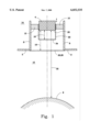
- FIG. 1 is a schematic showing the arrangement according to the invention for making contactless distance and pressure measurements within an air spring.
- the schematic shows a converter element elastically built into the cover plate of the air spring as well as first and second reference distances.
- An air spring essentially comprises a cover plate 2 which is attached to the vehicle frame or chassis, a flexible member and a roll-off piston attached at the wheel end or to the axle. With the aid of the resilient member, the roll-off piston can move relative to the cover plate 2.
- An ultrasonic measuring system is disposed within the air spring in order to determine the vehicle elevation which is dependent upon the particular loading state and spring deflection.
- the measuring system operates pursuant to the pulse/echo method.
- a piezoelectric transducer 4 operates as an ultrasonic pulse transmitter and receiver and is mounted on the cover plate 2.
- a reflector 6 or a surface suitable for reflection is disposed on the end of the roll-off piston lying opposite the ultrasonic transducer 4.
- the cover plate 2 includes a pipe-shaped stub 8.
- the ultrasonic transducer 4 is disposed in the pipe-shaped stub 8. This ultrasonic transducer 4 is elastically suspended.
- the elastic suspension 10 defines an air-tight closure of the interior space 12 of the spring relative to the ambient 14.
- the elastic suspension or mount 10 exhibits a specific pressure/displacement characteristic.
- the first reference distance 16 extends from the surface 20 of the transducer 4 to a first reflector 24.
- the reflector 24 is rigidly connected to the transducer 4 and is configured as a first wire bracket 22.
- the second reference distance 18 likewise begins at the surface 20 and extends to a second reflector 28.
- the second reflector 28 is configured as a second wire bracket 26 and is rigidly connected to the cover plate 2, more specifically, to the pipe stub 8.
- a measuring distance 30 which is known from the state of the art, is provided between the surface 20 of the transducer and the reflector 6 fixedly attached to the roll-off piston.
- the spring height can be determined in the conventional manner without knowledge of the sound speed from the ratio of the propagation time across measurement distance 30 to the propagation time across reference distance 16.
- the instantaneous pressure present in the interior 12 of the spring is determined from the pulse/echo signals of the first and second reference distances (16 and 18).
- the displacement of the elastically-supported sonic transducer 4, which is caused by the internal pressure, is provided by a comparison of the two propagation times.
- Elastic displacement and the pressure/displacement characteristic line of the elastic support 10 are, in turn, a measure for the internal pressure of the air spring.
- the knowledge of the pressure which is instantaneously present in the air spring, serves, for example, as a basis for computing the loading state or the particular wheel load.
Landscapes
- Engineering & Computer Science (AREA)
- Physics & Mathematics (AREA)
- General Physics & Mathematics (AREA)
- Computer Networks & Wireless Communication (AREA)
- Radar, Positioning & Navigation (AREA)
- Remote Sensing (AREA)
- Mechanical Engineering (AREA)
- Length Measuring Devices Characterised By Use Of Acoustic Means (AREA)
Abstract
The invention is directed to an arrangement for making contactless distance and pressure measurements within an air spring. With a single arrangement, the exact elevation of the spring as well as the spring pressure can be determined. This permits optimal utilization of the axle loads of a multi-axle vehicle and permits adjustment of the distance between the chassis and the axle. In the arrangement, an ultrasonic configuration makes contactless distance measurements in accordance with the pulse/echo method. The arrangement includes a transmitter/receiver component (4) mounted on the chassis and a first reflector (24) defining a first reference distance (16) therebetween. The component (4) and a reflector (6) define a measuring distance (30). The reflector (6) is fixedly mounted to the axle. The transmitter/receiver component (4) is elastically supported by a suspension (10) in a pipe stub (8) fixedly mounted to the chassis. A second reflector (28) is fixedly mounted on the pipe stub (8) and defines a second reference distance (18) to the component (4). The displacement of the elastically-supported component (4), which is caused by the internal pressure, is given by a comparison of the propagation times assigned to the two reference distances (16 and 18). In this way, the internal pressure of the air spring is determined.
Description
The invention relates to an arrangement for making contactless distance and pressure measurements within an air spring of a motor vehicle.
The distance between chassis and axle should not change for different loading states of the vehicle. For this reason, it is necessary to measure the height of the spring and to readjust the system by pumping or releasing air when there are deviations from the desired height. An air spring control is also required for optimal utilization of the axle load of a multi-axle vehicle.
Ultrasonic distance measurement in air is, for example, utilized for making fill-level measurements of vessels, to measure rooms of a dwelling, to make distance measurements when parking a motor vehicle, to make distance measurements in automatic focus cameras and the like.
German patent publication 3,423,602 discloses an arrangement for measuring the distance between the chassis and the axle of a vehicle utilizing an ultrasonic measuring system configured as a transmitter/receiver.
The advantage of utilizing ultrasonic sound within an air spring is that no turbulence of sound waves caused by the wind created by the movement of the vehicle is possible within the air spring.
On the other hand, the problem is present when making distance measurement within the air spring chamber that, in the air springs, pressure differences between 0 and approximately 20 bar and temperature ranges between -40° C. and +120° C. must be mastered. The speed of sound in a real gas, such as pumped-in air, is dependent to a great extent on pressure and temperature. For this reason, considerable errors result when basing the distance computation on a fixed pregiven speed of sound.
To avoid such errors, U.S. Pat. No. 4,798,369 discloses an ultrasonic air spring system wherein a compensation of the pressure and temperature dependency is provided by means of a computer circuit.
German patent publication 3,620,957 discloses an air spring having an ultrasonic pulse/echo system for making height measurements. An additional fixed target is proposed in order to cancel the effects of the changes in propagation speed of the pulses (the changes in propagation speed can occur because of air pressure, temperature and humidity changes in the interior of the resilient member of the air spring). In this way, a relative value for the propagation times is determined. It is not necessary to know the instantaneous speed of the sound to compute the vehicle elevation in this relative method.
The disadvantage with such a relative method while utilizing a reference distance (such a method is known in a comparable manner also for a telescope shock absorber as disclosed in German utility model registration G 87 02 817.4) is that the important variables of pressure and temperature cannot be explicitly displayed. The above-mentioned German utility model registration G 87 02 817.4 only discloses installing thermistors to compensate for temperature.
The spring pressure, which is of interest for the state of loading of the vehicle, the wheel load and the like, cannot be determined with any of the above-mentioned air spring measuring arrangements.
It is an object of the invention to provide an ultrasonic pulse/echo measuring system wherein the exact height of the spring as well as the pressure thereof are explicitly given with a single device.
The arrangement of the invention is for contactlessly making measurements of distance and pressure within an air spring of a motor vehicle. The air spring is delimited by a first part fixedly connected to the chassis of the motor vehicle and a second part fixedly connected to the axle of a wheel of the motor vehicle. The first and second parts are movable relative to each other causing the distance therebetween to vary. The arrangement includes: a transmitter/receiver assembly associated with the first part; the transmitter/receiver assembly including: a support structure fixedly mounted on the first part; an ultrasonic transmitter/receiver unit and a first reflector conjointly defining a first reference distance therebetween; an elastic mount for elastically suspending the ultrasonic transmitter/receiver unit and the first reflector in the support structure and the elastic mount being subject to a displacement in response to the pressure; a second reflector fixedly mounted on the support structure; the ultrasonic transmitter/receiver unit and the second reflector conjointly defining a second reference distance therebetween; a third reflector fixedly disposed on the second part; the third reflector and the ultrasonic transmitter/receiver unit conjointly defining a measuring distance therebetween; the elastic mount having a characteristic line defining the pressure as a function of the displacement of the mount in response to the pressure; and, the characteristic line being a first variable and the second reference distance being a second variable from which variables the pressure can be determined.
Pressure pick-ups, which operate on a strain gauge basis, or piezoelectric pick-ups are used in diverse areas of application. The second reference distance is a feature of the invention and coacts with an elastic suspension of the transducer. With this combination, it is possible for the first time, to determine with a single device the pressure parameter simultaneously with the spring elevation.
Preferably, the first reflector is defined by a first wire bracket and the second reflector is defined by a second wire bracket. The wire bracket reflectors according to the invention have a greater stability compared to a target in the form of a planar metal disc attached to a stem. This is especially significant for rough driving operations. Reflectors made of wire are especially simple and inexpensive to produce.
The data of interest, namely, vehicle elevation and spring pressure, are determined with the aid of a computer element from the measured pressure-dependent length of the second reference distance in combination with the known pressure/displacement characteristic of the suspension.
The invention will now be described with reference to the drawing wherein:
FIG. 1 is a schematic showing the arrangement according to the invention for making contactless distance and pressure measurements within an air spring. The schematic shows a converter element elastically built into the cover plate of the air spring as well as first and second reference distances.
An air spring essentially comprises a cover plate 2 which is attached to the vehicle frame or chassis, a flexible member and a roll-off piston attached at the wheel end or to the axle. With the aid of the resilient member, the roll-off piston can move relative to the cover plate 2.
An ultrasonic measuring system is disposed within the air spring in order to determine the vehicle elevation which is dependent upon the particular loading state and spring deflection. The measuring system operates pursuant to the pulse/echo method. For this purpose, a piezoelectric transducer 4 operates as an ultrasonic pulse transmitter and receiver and is mounted on the cover plate 2. A reflector 6 or a surface suitable for reflection is disposed on the end of the roll-off piston lying opposite the ultrasonic transducer 4.
In the embodiment shown, the cover plate 2 includes a pipe-shaped stub 8. The ultrasonic transducer 4 is disposed in the pipe-shaped stub 8. This ultrasonic transducer 4 is elastically suspended. The elastic suspension 10 defines an air-tight closure of the interior space 12 of the spring relative to the ambient 14. The elastic suspension or mount 10 exhibits a specific pressure/displacement characteristic.
Also shown in FIG. 1 is a first reference distance 16 and a second reference distance 18. The first reference distance 16 extends from the surface 20 of the transducer 4 to a first reflector 24. The reflector 24 is rigidly connected to the transducer 4 and is configured as a first wire bracket 22. The second reference distance 18 likewise begins at the surface 20 and extends to a second reflector 28. The second reflector 28 is configured as a second wire bracket 26 and is rigidly connected to the cover plate 2, more specifically, to the pipe stub 8.
In addition to the reference distances 16 and 18, a measuring distance 30, which is known from the state of the art, is provided between the surface 20 of the transducer and the reflector 6 fixedly attached to the roll-off piston.
The operation of the measuring arrangement according to the invention will now be described.
The spring height can be determined in the conventional manner without knowledge of the sound speed from the ratio of the propagation time across measurement distance 30 to the propagation time across reference distance 16.
In addition, and according to the invention, the instantaneous pressure present in the interior 12 of the spring is determined from the pulse/echo signals of the first and second reference distances (16 and 18). The displacement of the elastically-supported sonic transducer 4, which is caused by the internal pressure, is provided by a comparison of the two propagation times. Elastic displacement and the pressure/displacement characteristic line of the elastic support 10 are, in turn, a measure for the internal pressure of the air spring.
The knowledge of the pressure, which is instantaneously present in the air spring, serves, for example, as a basis for computing the loading state or the particular wheel load.
An electronic circuit appropriate for performing the computations referred to above is described with reference to FIG. 3 of U.S. patent application Ser. No. 08/976,426, filed on Nov. 21, 1997, and incorporated herein by reference.
It is understood that the foregoing description is that of the preferred embodiments of the invention and that various changes and modifications may be made thereto without departing from the spirit and scope of the invention as defined in the appended claims.
Claims (2)
1. An arrangement for contactlessly making measurements of distance and pressure within an air spring of a motor vehicle, the air spring being delimited by a first part fixedly connected to the chassis of said motor vehicle and a second part fixedly connected to the axle of a wheel of said motor vehicle, said first and second parts being movable relative to each other causing the distance therebetween to vary, the arrangement comprising:
a transmitter/receiver assembly associated with said first part;
said transmitter/receiver assembly including:
a support structure fixedly mounted on said first part;
an ultrasonic transmitter/receiver unit and a first reflector conjointly defining a first reference distance therebetween;
an elastic mount for elastically suspending said ultrasonic transmitter/receiver unit and said first reflector in said support structure and said elastic mount being subject to a displacement in response to said pressure;
a second reflector fixedly mounted on said support structure;
said ultrasonic transmitter/receiver unit and said second reflector conjointly defining a second reference distance therebetween;
a third reflector fixedly disposed on said second part;
said third reflector and said ultrasonic transmitter/receiver unit conjointly defining a measuring distance therebetween;
said elastic mount having a characteristic line defining said pressure as a function of said displacement of said mount in response to said pressure; and,
said characteristic line being a first variable and said second reference distance being a second variable from which variables said pressure can be determined.
2. The arrangement of claim 1, wherein said first reflector is a first wire bracket and said second reflector is a second wire bracket.
Applications Claiming Priority (2)
| Application Number | Priority Date | Filing Date | Title |
|---|---|---|---|
| DE19700966 | 1997-01-14 | ||
| DE19700966A DE19700966C1 (en) | 1997-01-14 | 1997-01-14 | Device for contactless distance and pressure measurement in a pneumatic spring |
Publications (1)
| Publication Number | Publication Date |
|---|---|
| US6032535A true US6032535A (en) | 2000-03-07 |
Family
ID=7817313
Family Applications (1)
| Application Number | Title | Priority Date | Filing Date |
|---|---|---|---|
| US09/006,442 Expired - Lifetime US6032535A (en) | 1997-01-14 | 1998-01-13 | Arrangement for making contactless distance and pressure measurements within an air spring |
Country Status (2)
| Country | Link |
|---|---|
| US (1) | US6032535A (en) |
| DE (1) | DE19700966C1 (en) |
Cited By (18)
| Publication number | Priority date | Publication date | Assignee | Title |
|---|---|---|---|---|
| US6223600B1 (en) * | 1998-08-29 | 2001-05-01 | Contitech Luftfedersysteme Gmbh | Air spring arrangement having a device for making ultrasonic distance measurements therein |
| WO2003000512A1 (en) * | 2001-06-21 | 2003-01-03 | Scania Cv Ab (Publ) | Arrangement for a commercial vehicle and a commercial vehicle |
| US20030074970A1 (en) * | 2001-10-18 | 2003-04-24 | Siegfried Reck | Method for determining the pressure present in the interior space of an air spring for a motor vehicle and apparatus for carrying out the method |
| EP1295737A3 (en) * | 2001-09-25 | 2003-07-02 | KNORR-BREMSE SYSTEME FÜR NUTZFAHRZEUGE GmbH | Determination of height and pressure in spring elements, especially air springs, for vehicles |
| US6634214B1 (en) * | 1998-01-16 | 2003-10-21 | Bg Intellectual Property Limited | Method and apparatus for measuring the relative density of a gas |
| US6637269B2 (en) * | 2000-10-19 | 2003-10-28 | Contitech Luftfedersystem Gmbh | Motor vehicle air spring system having an ultrasonic measurement arrangement |
| US20040007061A1 (en) * | 2002-07-12 | 2004-01-15 | Forgue John R. | Fluid level sensor |
| US20050110226A1 (en) * | 2003-10-08 | 2005-05-26 | Hitachi, Ltd. | Suspension device for vehicle |
| EP1314957A3 (en) * | 2001-11-16 | 2005-11-09 | General Electric Company | Method and apparatus for measuring turbine blade tip clearance |
| US20060267297A1 (en) * | 2005-05-28 | 2006-11-30 | Bfs Diversified Products, Llc | Air spring assembly with localized signal processing, system and method utilizing same, as well as operating module therefor |
| US20090277273A1 (en) * | 2008-05-06 | 2009-11-12 | Seung Soo Hong | Apparatus for measuring pressure in a vessel using acoustic impedance matching layers |
| US20100077617A1 (en) * | 2008-09-29 | 2010-04-01 | Mark Peterson | Razors and razor cartridges with a decreased total interblade span |
| US8517396B2 (en) | 2009-06-01 | 2013-08-27 | Firestone Industrial Products Company, Llc | Height control module, gas spring assembly and method |
| US8868294B2 (en) | 2012-09-28 | 2014-10-21 | Firestone Industrial Products Company, Llc | Adjustable hysteresis circuit for control of air suspension |
| US20150037053A1 (en) * | 2013-08-05 | 2015-02-05 | Canon Kabushiki Kaisha | Sheet determination apparatus using ultrasonic wave transmitting unit or reception unit |
| CN109444909A (en) * | 2018-12-25 | 2019-03-08 | 常州诺米电子科技有限公司 | A kind of laser range finder with swing preventing function |
| EP3680030A1 (en) * | 2019-01-14 | 2020-07-15 | Continental Automotive GmbH | Ultrasonic transducer device and air suspension device comprising the ultrasonic transducer device |
| CN111426346A (en) * | 2020-04-09 | 2020-07-17 | 深圳了然视觉科技有限公司 | Vision-based sensor and sensing method |
Families Citing this family (3)
| Publication number | Priority date | Publication date | Assignee | Title |
|---|---|---|---|---|
| DE19820877C2 (en) * | 1998-05-09 | 2002-09-19 | Contitech Luftfedersyst Gmbh | Non-contact distance and pressure measurement within an air spring |
| DE102006025326B4 (en) * | 2006-05-31 | 2017-05-04 | Contitech Luftfedersysteme Gmbh | Determination of the spring height of an air spring according to a pulse transit time measurement method |
| DE102012220412B3 (en) | 2012-11-28 | 2014-03-27 | Seca Ag | length measuring instrument |
Citations (10)
| Publication number | Priority date | Publication date | Assignee | Title |
|---|---|---|---|---|
| US2743429A (en) * | 1950-10-14 | 1956-04-24 | Electrocircuits Inc | Automatic positioning device |
| US4543649A (en) * | 1983-10-17 | 1985-09-24 | Teknar, Inc. | System for ultrasonically detecting the relative position of a moveable device |
| US4561064A (en) * | 1982-03-05 | 1985-12-24 | Brueggen Gerhard | Non-contacting distance measuring system |
| DE3423602A1 (en) * | 1984-06-27 | 1986-01-09 | Robert Bosch Gmbh, 7000 Stuttgart | Device for measuring the distance between the chassis and the axle of a vehicle |
| DE3620957A1 (en) * | 1985-07-02 | 1987-01-08 | Dunlop Ltd | SUSPENSION SYSTEM |
| DE8702817U1 (en) * | 1986-02-24 | 1987-05-14 | Marelli Autronica S.P.A., Mailand/Milano | Device for indicating the movements of a movable part of a telescopic shock absorber for motor vehicles in relation to the fixed part |
| US4798369A (en) * | 1987-11-03 | 1989-01-17 | The Firestone Tire & Rubber Company | Ultrasonic air spring system |
| US4938066A (en) * | 1988-01-29 | 1990-07-03 | Xecutek Corporation | Ultrasonic apparatus for measuring the speed of sound in a gaseous medium |
| US5859692A (en) * | 1997-05-16 | 1999-01-12 | Rochester Gauges, Inc. | Height sensor and air spring apparatus incorporating the same in the air chamber |
| US5936161A (en) * | 1996-11-21 | 1999-08-10 | Contitech Luftfedersysteme Gmbh | Arrangement for making contactless distance measurements |
-
1997
- 1997-01-14 DE DE19700966A patent/DE19700966C1/en not_active Expired - Fee Related
-
1998
- 1998-01-13 US US09/006,442 patent/US6032535A/en not_active Expired - Lifetime
Patent Citations (10)
| Publication number | Priority date | Publication date | Assignee | Title |
|---|---|---|---|---|
| US2743429A (en) * | 1950-10-14 | 1956-04-24 | Electrocircuits Inc | Automatic positioning device |
| US4561064A (en) * | 1982-03-05 | 1985-12-24 | Brueggen Gerhard | Non-contacting distance measuring system |
| US4543649A (en) * | 1983-10-17 | 1985-09-24 | Teknar, Inc. | System for ultrasonically detecting the relative position of a moveable device |
| DE3423602A1 (en) * | 1984-06-27 | 1986-01-09 | Robert Bosch Gmbh, 7000 Stuttgart | Device for measuring the distance between the chassis and the axle of a vehicle |
| DE3620957A1 (en) * | 1985-07-02 | 1987-01-08 | Dunlop Ltd | SUSPENSION SYSTEM |
| DE8702817U1 (en) * | 1986-02-24 | 1987-05-14 | Marelli Autronica S.P.A., Mailand/Milano | Device for indicating the movements of a movable part of a telescopic shock absorber for motor vehicles in relation to the fixed part |
| US4798369A (en) * | 1987-11-03 | 1989-01-17 | The Firestone Tire & Rubber Company | Ultrasonic air spring system |
| US4938066A (en) * | 1988-01-29 | 1990-07-03 | Xecutek Corporation | Ultrasonic apparatus for measuring the speed of sound in a gaseous medium |
| US5936161A (en) * | 1996-11-21 | 1999-08-10 | Contitech Luftfedersysteme Gmbh | Arrangement for making contactless distance measurements |
| US5859692A (en) * | 1997-05-16 | 1999-01-12 | Rochester Gauges, Inc. | Height sensor and air spring apparatus incorporating the same in the air chamber |
Cited By (29)
| Publication number | Priority date | Publication date | Assignee | Title |
|---|---|---|---|---|
| US6634214B1 (en) * | 1998-01-16 | 2003-10-21 | Bg Intellectual Property Limited | Method and apparatus for measuring the relative density of a gas |
| US6223600B1 (en) * | 1998-08-29 | 2001-05-01 | Contitech Luftfedersysteme Gmbh | Air spring arrangement having a device for making ultrasonic distance measurements therein |
| US6637269B2 (en) * | 2000-10-19 | 2003-10-28 | Contitech Luftfedersystem Gmbh | Motor vehicle air spring system having an ultrasonic measurement arrangement |
| EP1199196A3 (en) * | 2000-10-19 | 2003-12-03 | ContiTech Luftfedersysteme GmbH | Vehicle air suspension system with ultrasound measuring arrangement |
| WO2003000512A1 (en) * | 2001-06-21 | 2003-01-03 | Scania Cv Ab (Publ) | Arrangement for a commercial vehicle and a commercial vehicle |
| EP1295737A3 (en) * | 2001-09-25 | 2003-07-02 | KNORR-BREMSE SYSTEME FÜR NUTZFAHRZEUGE GmbH | Determination of height and pressure in spring elements, especially air springs, for vehicles |
| US20030074970A1 (en) * | 2001-10-18 | 2003-04-24 | Siegfried Reck | Method for determining the pressure present in the interior space of an air spring for a motor vehicle and apparatus for carrying out the method |
| US6931930B2 (en) * | 2001-10-18 | 2005-08-23 | Contitech Luftfedersysteme Gmbh | Method for determining the pressure present in the interior space of an air spring for a motor vehicle and apparatus for carrying out the method |
| EP1314957A3 (en) * | 2001-11-16 | 2005-11-09 | General Electric Company | Method and apparatus for measuring turbine blade tip clearance |
| EP2275776A3 (en) * | 2001-11-16 | 2011-09-28 | General Electric Company | Method and apparatus for measuring turbine blade tip clearance |
| KR100806441B1 (en) * | 2001-11-16 | 2008-02-21 | 제너럴 일렉트릭 캄파니 | Method and apparatus for measuring turbine blade tip clearance |
| US20040007061A1 (en) * | 2002-07-12 | 2004-01-15 | Forgue John R. | Fluid level sensor |
| US6993967B2 (en) | 2002-07-12 | 2006-02-07 | Ti Group Automotive Systems, L.L.C. | Fluid level sensor |
| EP1522431A3 (en) * | 2003-10-08 | 2005-10-05 | Hitachi, Ltd. | Suspension device for vehicle |
| US20050110226A1 (en) * | 2003-10-08 | 2005-05-26 | Hitachi, Ltd. | Suspension device for vehicle |
| US20060267297A1 (en) * | 2005-05-28 | 2006-11-30 | Bfs Diversified Products, Llc | Air spring assembly with localized signal processing, system and method utilizing same, as well as operating module therefor |
| US7621538B2 (en) | 2005-05-28 | 2009-11-24 | Bfs Diversified Products, Llc | Air spring assembly with localized signal processing, system and method utilizing same, as well as operating module therefor |
| US20090277273A1 (en) * | 2008-05-06 | 2009-11-12 | Seung Soo Hong | Apparatus for measuring pressure in a vessel using acoustic impedance matching layers |
| US20100077617A1 (en) * | 2008-09-29 | 2010-04-01 | Mark Peterson | Razors and razor cartridges with a decreased total interblade span |
| US8517396B2 (en) | 2009-06-01 | 2013-08-27 | Firestone Industrial Products Company, Llc | Height control module, gas spring assembly and method |
| US8868294B2 (en) | 2012-09-28 | 2014-10-21 | Firestone Industrial Products Company, Llc | Adjustable hysteresis circuit for control of air suspension |
| US20150037053A1 (en) * | 2013-08-05 | 2015-02-05 | Canon Kabushiki Kaisha | Sheet determination apparatus using ultrasonic wave transmitting unit or reception unit |
| US9874842B2 (en) * | 2013-08-05 | 2018-01-23 | Canon Kabushiki Kaisha | Sheet determination apparatus using ultrasonic wave transmitting unit or reception unit |
| US20180095394A1 (en) * | 2013-08-05 | 2018-04-05 | Canon Kabushiki Kaisha | Sheet determination apparatus using ultrasonic wave transmitting unit or reception unit |
| US10884368B2 (en) | 2013-08-05 | 2021-01-05 | Canon Kabushiki Kaisha | Sheet determination apparatus using ultrasonic wave transmitting unit or reception unit |
| CN109444909A (en) * | 2018-12-25 | 2019-03-08 | 常州诺米电子科技有限公司 | A kind of laser range finder with swing preventing function |
| EP3680030A1 (en) * | 2019-01-14 | 2020-07-15 | Continental Automotive GmbH | Ultrasonic transducer device and air suspension device comprising the ultrasonic transducer device |
| WO2020148040A1 (en) * | 2019-01-14 | 2020-07-23 | Continental Automotive Gmbh | Ultrasonic transducer device and air suspension device comprising the ultrasonic transducer device |
| CN111426346A (en) * | 2020-04-09 | 2020-07-17 | 深圳了然视觉科技有限公司 | Vision-based sensor and sensing method |
Also Published As
| Publication number | Publication date |
|---|---|
| DE19700966C1 (en) | 1998-04-23 |
Similar Documents
| Publication | Publication Date | Title |
|---|---|---|
| US6032535A (en) | Arrangement for making contactless distance and pressure measurements within an air spring | |
| US6073491A (en) | Method and arrangement for making contactless distance and pressure measurements within an air spring | |
| EP0542865B1 (en) | A suspension system with improved resonance damping and a method for regulating the suspension system | |
| US5000478A (en) | Shock absorber with Doppler fluid velocity sensor | |
| EP0808734B1 (en) | Suspension control apparatus with vehicle sprung- and unsprung- structure relative-velocity computing apparatus. | |
| JP2009524062A (en) | Distance display system and method | |
| JPH05502646A (en) | Shock absorber with sonar position sensor | |
| US9452657B1 (en) | Height determination for two independently suspended wheels using a height sensor for only one wheel | |
| EP0551986A1 (en) | Height sensor and air spring device incorporating the same | |
| JPS59126261A (en) | Accelerometer with needle resonator power transducer | |
| US20020046608A1 (en) | Motor vehicle air spring system having an ultrasonic mesurement arrangement | |
| CN114207312A (en) | Gas spring sensor using millimeter wavelength radar, and gas spring assembly and suspension system including the same | |
| US20190111751A1 (en) | Internal gas spring displacement sensors as well as gas spring assemblies and suspension systems including same | |
| US5083454A (en) | Force-operated suspension position sensor for automotive vehicle | |
| JPH09152389A (en) | Shock absorber damping force measuring device | |
| US5600955A (en) | Hydraulic servoactuator stabilizer device | |
| JP2005112155A (en) | Suspension device | |
| JPH04221217A (en) | Method for measuring relative motion to hydraulic actuator | |
| US11597249B2 (en) | Internal damper sensors as well as damper assemblies and suspension systems including same | |
| US5309760A (en) | Method and apparatus for measuring the content of a storage vessel | |
| CN113484031B (en) | Method for setting noise transfer function target of suspension attachment point | |
| JPH0735646A (en) | Apparatus for measuring characteristic of leaf spring | |
| US20240286449A1 (en) | Compliant mechanism for suspension height sensor | |
| JPH1172132A (en) | Measurement device for relative behavior of sprung and unsprung structures | |
| MXPA98000389A (en) | Device for non-contact measurement of distance and pressure within a neumat spring |
Legal Events
| Date | Code | Title | Description |
|---|---|---|---|
| AS | Assignment |
Owner name: CONTITECH LUFTFEDERSYSTEME GMBH, GERMANY Free format text: ASSIGNMENT OF ASSIGNORS INTEREST;ASSIGNORS:FISCHER, NORBERT;ALTSINGER, ROLAND;REEL/FRAME:009229/0774;SIGNING DATES FROM 19980123 TO 19980128 |
|
| FEPP | Fee payment procedure |
Free format text: PAYOR NUMBER ASSIGNED (ORIGINAL EVENT CODE: ASPN); ENTITY STATUS OF PATENT OWNER: LARGE ENTITY |
|
| STCF | Information on status: patent grant |
Free format text: PATENTED CASE |
|
| FPAY | Fee payment |
Year of fee payment: 4 |
|
| FPAY | Fee payment |
Year of fee payment: 8 |
|
| FPAY | Fee payment |
Year of fee payment: 12 |