US6022194A - Linear priction welding of steeples and device thereof - Google Patents
Linear priction welding of steeples and device thereof Download PDFInfo
- Publication number
- US6022194A US6022194A US08/877,844 US87784497A US6022194A US 6022194 A US6022194 A US 6022194A US 87784497 A US87784497 A US 87784497A US 6022194 A US6022194 A US 6022194A
- Authority
- US
- United States
- Prior art keywords
- steeple
- steeples
- providing
- steel
- blade
- Prior art date
- Legal status (The legal status is an assumption and is not a legal conclusion. Google has not performed a legal analysis and makes no representation as to the accuracy of the status listed.)
- Expired - Lifetime
Links
Images

Classifications
-
- F—MECHANICAL ENGINEERING; LIGHTING; HEATING; WEAPONS; BLASTING
- F01—MACHINES OR ENGINES IN GENERAL; ENGINE PLANTS IN GENERAL; STEAM ENGINES
- F01D—NON-POSITIVE DISPLACEMENT MACHINES OR ENGINES, e.g. STEAM TURBINES
- F01D5/00—Blades; Blade-carrying members; Heating, heat-insulating, cooling or antivibration means on the blades or the members
- F01D5/30—Fixing blades to rotors; Blade roots ; Blade spacers
- F01D5/3061—Fixing blades to rotors; Blade roots ; Blade spacers by welding, brazing
-
- F—MECHANICAL ENGINEERING; LIGHTING; HEATING; WEAPONS; BLASTING
- F01—MACHINES OR ENGINES IN GENERAL; ENGINE PLANTS IN GENERAL; STEAM ENGINES
- F01D—NON-POSITIVE DISPLACEMENT MACHINES OR ENGINES, e.g. STEAM TURBINES
- F01D5/00—Blades; Blade-carrying members; Heating, heat-insulating, cooling or antivibration means on the blades or the members
- F01D5/02—Blade-carrying members, e.g. rotors
-
- F—MECHANICAL ENGINEERING; LIGHTING; HEATING; WEAPONS; BLASTING
- F01—MACHINES OR ENGINES IN GENERAL; ENGINE PLANTS IN GENERAL; STEAM ENGINES
- F01D—NON-POSITIVE DISPLACEMENT MACHINES OR ENGINES, e.g. STEAM TURBINES
- F01D5/00—Blades; Blade-carrying members; Heating, heat-insulating, cooling or antivibration means on the blades or the members
- F01D5/30—Fixing blades to rotors; Blade roots ; Blade spacers
- F01D5/3007—Fixing blades to rotors; Blade roots ; Blade spacers of axial insertion type
-
- Y—GENERAL TAGGING OF NEW TECHNOLOGICAL DEVELOPMENTS; GENERAL TAGGING OF CROSS-SECTIONAL TECHNOLOGIES SPANNING OVER SEVERAL SECTIONS OF THE IPC; TECHNICAL SUBJECTS COVERED BY FORMER USPC CROSS-REFERENCE ART COLLECTIONS [XRACs] AND DIGESTS
- Y10—TECHNICAL SUBJECTS COVERED BY FORMER USPC
- Y10T—TECHNICAL SUBJECTS COVERED BY FORMER US CLASSIFICATION
- Y10T29/00—Metal working
- Y10T29/49—Method of mechanical manufacture
- Y10T29/49316—Impeller making
- Y10T29/4932—Turbomachine making
- Y10T29/49321—Assembling individual fluid flow interacting members, e.g., blades, vanes, buckets, on rotary support member
Definitions
- This invention relates to turbines. More specifically, this invention relates to the engagement of blades onto discs or rotor discs of turbines.
- Steam turbines and rotors are constructed of discs or rotor discs that have a number of circumferentially disposed projecting steeples.
- These steeples can be distressed in a number of ways.
- the steeples may incur mechanical damage from foreign objects.
- the steeples are susceptible to stress corrosion cracking and pitting, corrosion, erosion corrosion, high cycle fatigue, and other factors.
- the environment in especially low pressure steam turbines, with all of its steam borne corroding components promotes the corrosion of the steeples. These damage mechanisms evidence themselves by pitting and cracking the steeples and surrounding rim area, or substantial metal wastage thereof, and can lead to scrapping the entire rotor at great expense to the operator.
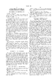
- Prior Art FIG. 1 the prior art discloses that the steeples on a disc 10 can be repaired by removing the distressed steeples and restoring the area with a solid weld metal buildup 12. The buildup 12 is then machined down to form a replacement steeple 14. A space 16 on disc 10 is where there was previously a distressed steeple that has been removed to prepare for another solid weld metal buildup.
- a disc particularly one used in a nuclear steam turbine which is more prone to stress corrosion cracking, may be as large as 100 inches in diameter. Repairing the steeples on an entire disc can take between 500 and 1000 hours. This time can be increased if weld defects are detected and corrected. Therefore, it is clear that a more economical method to repair the steeples is needed.
- the invention provides a blade-rotating device for rotating a plurality of radially-oriented blades having a blade base with two grooved base sides.
- the device has a portion, such as a disc or a rotor disc of a turbine, for rotating the blades with the portion having an outer cylindrical surface.
- the device also has a plurality of steel steeples each having a steeple base and two opposite grooved steeple sides extending therefrom. Each of the opposite steeple sides complements at least one of the grooved sides of at least one of the blade bases.
- the steeple bases are linear friction welded to the outer cylindrical surface in an approximately longitudinal direction such that the blade bases are engagable with the steel steeples.
- FIG. 1 is a detail view of steeples on a disc being replaced using prior art techniques.
- FIG. 2 is a perspective view of a steel steeple according to the claimed invention.
- FIG. 3 is a view of a disc with the original steeples.
- FIG. 4 is a perspective view of a disc according to the claimed invention.
- FIG. 5 is a sectional perspective view of steel steeples that have been linear friction welded onto the disc as per the claimed invention.
- FIG. 6 is an example of a typical turbine blade
- FIG. 7 is a detail of turbine blades engaged with the steel steeples of the claimed invention.
- FIG. 8 is an example of a typical disc with radially-oriented blades engaged with the steel steeples of the claimed invention.
- FIG. 2 a steel steeple 20 having a steeple base 22 of a thickness 23.
- the steeple may be forged, hot-rolled, or any other suitable steeple type.
- the steeple 20 has a front end 24, a back end 26 (not shown), and two opposite, grooved steeple sides 28 extending therefrom.
- the grooved steeple sides 28 have grooves 30 extending from the front end 24 to the back end 26.
- the grooved steeple sides 28 are designed to complement the blade base 44 of the blades 42, which is discussed below (see description of FIGS. 7 and 8). While the embodiment of the invention shown in FIG.
- the steeple 20 may be oversized, In a further preferred embodiment of the invention, the steel steeple may be oversized 0.070 inches.
- the steel steeple may be made of a NiCrMoV alloy. In a more preferred embodiment of the invention, the steel steeple may comprise 9% to 17% chromium. In a further preferred embodiment of the invention, the steel steeple may comprise approximately 12% chromium. These percentages of chromium provide enhanced corrosion resistance to the steel steeple 20. In another preferred embodiment, the alloy may be 3.5 NiCrMoV alloy.
- a disc 32 is a rotating means for rotating a plurality of radially-oriented blades 42 (see FIG. 8), having original steeples 18 disposed around its circumference.
- the disc 32 of FIG. 3 is shown prior to its preparation for linear friction welding the steeples 20 thereon.
- the disc 32 has a bore 34 extending therethrough for mounting the disc on a shaft (not shown).
- Other embodiments of the invention may use a rotor disc that is integral to the rotor (not shown). Details of the arrangement of discs on a shaft or of a rotor disc are disclosed in commonly assigned, co-pending application filed on Dec.
- the disc 32 has a radius 37 that does not include the original steeples 18 and an overall radius 38 that does include the original steeples.
- the disc 32 has been prepared to have the steel steeples 20 linear friction welded thereon.
- the original steeples 18 have been removed and an outer cylindrical surface 36 has been prepared to accept the steeples 20.
- Other embodiments of the invention may remove only a portion of the original steeples 18.
- the radius of the disc 32 has been reduced to a radius 39, which is radius 37 minus the thickness 23 of the steeple base 22.
- the reduced radius 39 is to ensure that the overall radius 38 remains the same after linear friction welding the steeples 20 onto the disc 32.
- the outer cylindrical surface 36 may be cladded.
- the steel steeples 20 have been linear friction welded onto the outer cylindrical surface 36.
- Examples of linear friction welding are disclosed in U.S. Pat. No. 5,486,262 to Searle entitled “Friction Welding”; and U.S. Pat. No. 5,492,581 to Searle entitled “Friction Welding”, both of which are incorporated herein by reference in their entireties.
- a steeple 20 is linear friction welded onto the outer cylindrical surface 36 by reciprocating at least one of them, preferably the steeple, and urging the two together such that the frictional heat generated between the components melts the material of at least one of the steeple 20 and the surface 36, and usually both, so as to form a friction weld.
- the steeples 20 are linear friction welded to the outer cylindrical surface 36 in an approximately longitudinal direction such that the grooved steeple sides 28 face an opposing steeple side 28 of an adjacent steeple. These pairs of facing steeple sides 28 complement at least one of the blade bases 44 (described below) and define grooved valleys 40.
- the steel steeples 20 are machined to remove the oversized portion thereon. It is estimated that the invention requires 30 seconds to friction weld a steeple onto the disc, or two hours to completely friction weld the steeples onto the disc, compared to the 500 to 1000 hours required in the weld metal buildup method.
- blade 42 is an example of blades commonly used in conjunction with the invention.
- FIG. 6 shows the blade base 44 and a bottom portion of the blade 42 extending therefrom to enable viewing of the blade base 44 details.
- the blade 42 extends further up, as shown in FIG. 8.
- Extending from the bottom of the blade is the blade base 44 having two opposite grooved base sides 46, a front end 48, and a back end 50.
- the grooved base sides 46 have grooves 52 extending from the front end 48 to the back end 50.
- the blade base 44 may be curved, as is shown in FIG. 6, straight, or skewed.
- a plurality of blade bases 44 are disposed in the grooved valleys 40 between the steel steeples 20.
- the grooved steeple sides 28 that define each grooved valley 40 complement and engage the blade base 44 disposed therein.
- the disposing of the blade bases 44 into the grooved valleys 40 radially orients the blades 42 around the disc 32.
- the grooves 30 in the grooved steeple sides 28 and the grooves 52 in the grooved base sides 46 are designed such that when the disc 32 rotates the blades 42, the blades remain relatively static compared to the outer cylindrical surface 36 and do not move in a radial direction.
- the disc 32 has an entire set of blade bases 44 disposed in the grooved valleys 40 formed by the steel steeples 20 that have been linear friction welded onto the outer cylindrical surface 36 of the disc 32 such that the blades 42 are radially oriented.
Landscapes
- Engineering & Computer Science (AREA)
- Mechanical Engineering (AREA)
- General Engineering & Computer Science (AREA)
- Pressure Welding/Diffusion-Bonding (AREA)
- Turbine Rotor Nozzle Sealing (AREA)
Abstract
Description
Claims (48)
Priority Applications (1)
| Application Number | Priority Date | Filing Date | Title |
|---|---|---|---|
| US08/877,844 US6022194A (en) | 1997-06-18 | 1997-06-18 | Linear priction welding of steeples and device thereof |
Applications Claiming Priority (1)
| Application Number | Priority Date | Filing Date | Title |
|---|---|---|---|
| US08/877,844 US6022194A (en) | 1997-06-18 | 1997-06-18 | Linear priction welding of steeples and device thereof |
Publications (1)
| Publication Number | Publication Date |
|---|---|
| US6022194A true US6022194A (en) | 2000-02-08 |
Family
ID=25370842
Family Applications (1)
| Application Number | Title | Priority Date | Filing Date |
|---|---|---|---|
| US08/877,844 Expired - Lifetime US6022194A (en) | 1997-06-18 | 1997-06-18 | Linear priction welding of steeples and device thereof |
Country Status (1)
| Country | Link |
|---|---|
| US (1) | US6022194A (en) |
Cited By (9)
| Publication number | Priority date | Publication date | Assignee | Title |
|---|---|---|---|---|
| US20030168494A1 (en) * | 2002-03-07 | 2003-09-11 | The Boeing Company | Preforms for forming machined structural assemblies |
| GB2387203A (en) * | 2002-04-02 | 2003-10-08 | Rolls Royce Plc | Rotor disc for a gas turbine engine |
| US20050050705A1 (en) * | 2003-09-10 | 2005-03-10 | Siemens Westinghouse Power Corporation | Repair of nickel-based alloy turbine disk |
| US20070175032A1 (en) * | 2006-01-31 | 2007-08-02 | Rolls-Royce Plc | Aerofoil assembly and a method of manufacturing an aerofoil assembly |
| US20120183409A1 (en) * | 2009-09-30 | 2012-07-19 | Christoph Ebert | Turbine blade, turbine shaft, turbine system and method for installing the turbine blade |
| US20140314473A1 (en) * | 2011-11-16 | 2014-10-23 | Basf Se | Process for connecting functional elements to a shaft |
| US8961144B2 (en) | 2011-06-30 | 2015-02-24 | General Electric Company | Turbine disk preform, welded turbine rotor made therewith and methods of making the same |
| US20150078904A1 (en) * | 2013-09-17 | 2015-03-19 | General Electric Company | Repaired turbine rotor wheel dovetail and related method |
| US10041163B1 (en) | 2017-02-03 | 2018-08-07 | Ge-Hitachi Nuclear Energy Americas Llc | Plasma spray coating for sealing a defect area in a workpiece |
Citations (5)
| Publication number | Priority date | Publication date | Assignee | Title |
|---|---|---|---|---|
| US4940390A (en) * | 1988-05-05 | 1990-07-10 | Westinghouse Electric Corp. | Turbine system having more failure resistant rotors and repair welding of low alloy ferrous turbine components by controlled weld build-up |
| US5024582A (en) * | 1990-08-14 | 1991-06-18 | Westinghouse Electric Corp. | Steam turbine rotor having graded weldments |
| US5486262A (en) * | 1993-05-13 | 1996-01-23 | Rolls-Royce Plc | Friction welding |
| US5492581A (en) * | 1993-05-13 | 1996-02-20 | Rolls-Royce Plc | Friction welding |
| US5746579A (en) * | 1996-12-27 | 1998-05-05 | Westinghouse Electric Corporation | Stress corrosion resistant rims and discs for steam turbine rotors device and method |
-
1997
- 1997-06-18 US US08/877,844 patent/US6022194A/en not_active Expired - Lifetime
Patent Citations (5)
| Publication number | Priority date | Publication date | Assignee | Title |
|---|---|---|---|---|
| US4940390A (en) * | 1988-05-05 | 1990-07-10 | Westinghouse Electric Corp. | Turbine system having more failure resistant rotors and repair welding of low alloy ferrous turbine components by controlled weld build-up |
| US5024582A (en) * | 1990-08-14 | 1991-06-18 | Westinghouse Electric Corp. | Steam turbine rotor having graded weldments |
| US5486262A (en) * | 1993-05-13 | 1996-01-23 | Rolls-Royce Plc | Friction welding |
| US5492581A (en) * | 1993-05-13 | 1996-02-20 | Rolls-Royce Plc | Friction welding |
| US5746579A (en) * | 1996-12-27 | 1998-05-05 | Westinghouse Electric Corporation | Stress corrosion resistant rims and discs for steam turbine rotors device and method |
Cited By (19)
| Publication number | Priority date | Publication date | Assignee | Title |
|---|---|---|---|---|
| US20040094604A1 (en) * | 2002-03-07 | 2004-05-20 | The Boeing Company | Machined structural assemblies formed from preforms |
| US6910616B2 (en) * | 2002-03-07 | 2005-06-28 | The Boeing Company | Preforms for forming machined structural assemblies |
| US20030168494A1 (en) * | 2002-03-07 | 2003-09-11 | The Boeing Company | Preforms for forming machined structural assemblies |
| GB2387203A (en) * | 2002-04-02 | 2003-10-08 | Rolls Royce Plc | Rotor disc for a gas turbine engine |
| US20040005219A1 (en) * | 2002-04-02 | 2004-01-08 | Phipps Anthony B. | Rotor disc for gas turbine engine |
| US6893226B2 (en) | 2002-04-02 | 2005-05-17 | Rolls-Royce Plc | Rotor disc for gas turbine engine |
| GB2387203B (en) * | 2002-04-02 | 2005-10-05 | Rolls Royce Plc | Rotor disc for gas turbine engine |
| US8266800B2 (en) * | 2003-09-10 | 2012-09-18 | Siemens Energy, Inc. | Repair of nickel-based alloy turbine disk |
| US20050050705A1 (en) * | 2003-09-10 | 2005-03-10 | Siemens Westinghouse Power Corporation | Repair of nickel-based alloy turbine disk |
| US20070175032A1 (en) * | 2006-01-31 | 2007-08-02 | Rolls-Royce Plc | Aerofoil assembly and a method of manufacturing an aerofoil assembly |
| US8656589B2 (en) * | 2006-01-31 | 2014-02-25 | Rolls-Royce Plc | Aerofoil assembly and a method of manufacturing an aerofoil assembly |
| US20120183409A1 (en) * | 2009-09-30 | 2012-07-19 | Christoph Ebert | Turbine blade, turbine shaft, turbine system and method for installing the turbine blade |
| US8961144B2 (en) | 2011-06-30 | 2015-02-24 | General Electric Company | Turbine disk preform, welded turbine rotor made therewith and methods of making the same |
| US20140314473A1 (en) * | 2011-11-16 | 2014-10-23 | Basf Se | Process for connecting functional elements to a shaft |
| US10539191B2 (en) * | 2011-11-16 | 2020-01-21 | List Technology Ag | Process for connecting functional elements to a shaft |
| US20150078904A1 (en) * | 2013-09-17 | 2015-03-19 | General Electric Company | Repaired turbine rotor wheel dovetail and related method |
| US9546551B2 (en) * | 2013-09-17 | 2017-01-17 | General Electric Company | Repaired turbine rotor wheel dovetail and related method |
| US10337329B2 (en) * | 2013-09-17 | 2019-07-02 | General Electric Company | Method and system to repair outer periphery of a body |
| US10041163B1 (en) | 2017-02-03 | 2018-08-07 | Ge-Hitachi Nuclear Energy Americas Llc | Plasma spray coating for sealing a defect area in a workpiece |
Similar Documents
| Publication | Publication Date | Title |
|---|---|---|
| CA2405335C (en) | Gas turbine engine compressor blade restoration | |
| US7690094B2 (en) | Impeller weld restraining fixture | |
| US7959409B2 (en) | Repaired vane assemblies and methods of repairing vane assemblies | |
| US4924581A (en) | Turbine air seal repair process | |
| US5846057A (en) | Laser shock peening for gas turbine engine weld repair | |
| US6568077B1 (en) | Blisk weld repair | |
| US20060277753A1 (en) | Method of repairing a blade member | |
| US5033938A (en) | Repaired turbine blade and method of repairing | |
| US20070157447A1 (en) | Method of improving the properties of a repaired component and a component improved thereby | |
| US5060842A (en) | Method for refurbishing nozzle block vanes of a steam turbine | |
| US6022194A (en) | Linear priction welding of steeples and device thereof | |
| JPH04262871A (en) | Welding repair method for cylindrical members | |
| US20020119730A1 (en) | Method of forming a trailing edge cutback for a turbine bucket | |
| US9163511B2 (en) | Steam turbine bucket tenon restoration through solid state bonding process | |
| US20050050705A1 (en) | Repair of nickel-based alloy turbine disk | |
| US7247000B2 (en) | Weld shielding device for automated welding of impellers and blisks | |
| US8911205B2 (en) | Method of repairing knife edge seals | |
| EP1564371B1 (en) | Method of repair a foot of a cast stator vane segment | |
| US10337329B2 (en) | Method and system to repair outer periphery of a body | |
| CA2618515A1 (en) | Method for securing a threaded insert in a threaded opening | |
| GB2091140A (en) | Turbine blades repair | |
| CA2068240A1 (en) | Parts for and methods of repairing turbine blades | |
| RU2740442C2 (en) | Axle compressor blisk and rotor of low-pressure compressor of aircraft gas turbine engine | |
| CA2106425A1 (en) | Method of restoring the bore of a turbo-machine rotor | |
| WO1993025340A1 (en) | Turbine rotors |
Legal Events
| Date | Code | Title | Description |
|---|---|---|---|
| AS | Assignment |
Owner name: WESTINGHOUSE ELECTRIC CORPORATION, PENNSYLVANIA Free format text: ASSIGNMENT OF ASSIGNORS INTEREST;ASSIGNORS:AMOS, DENNIS RAY;BACHMAN, SALLIE ANN;REEL/FRAME:008606/0768 Effective date: 19970516 |
|
| FEPP | Fee payment procedure |
Free format text: PAYOR NUMBER ASSIGNED (ORIGINAL EVENT CODE: ASPN); ENTITY STATUS OF PATENT OWNER: LARGE ENTITY |
|
| AS | Assignment |
Owner name: SIEMENS WESTINGHOUSE POWER CORPORATION, FLORIDA Free format text: NUNC PRO TUNC ASSIGNMENT;ASSIGNOR:CBS CORPORATION, FORMERLY KNOWN AS WESTINGHOUSE ELECTRIC CORP.;REEL/FRAME:009827/0570 Effective date: 19980929 |
|
| STCF | Information on status: patent grant |
Free format text: PATENTED CASE |
|
| FPAY | Fee payment |
Year of fee payment: 4 |
|
| AS | Assignment |
Owner name: SIEMENS POWER GENERATION, INC., FLORIDA Free format text: CHANGE OF NAME;ASSIGNOR:SIEMENS WESTINGHOUSE POWER CORPORATION;REEL/FRAME:016996/0491 Effective date: 20050801 |
|
| FPAY | Fee payment |
Year of fee payment: 8 |
|
| AS | Assignment |
Owner name: SIEMENS ENERGY, INC., FLORIDA Free format text: CHANGE OF NAME;ASSIGNOR:SIEMENS POWER GENERATION, INC.;REEL/FRAME:022482/0740 Effective date: 20081001 Owner name: SIEMENS ENERGY, INC.,FLORIDA Free format text: CHANGE OF NAME;ASSIGNOR:SIEMENS POWER GENERATION, INC.;REEL/FRAME:022482/0740 Effective date: 20081001 |
|
| FPAY | Fee payment |
Year of fee payment: 12 |