US6019928A - Method for resin insert molding a connector block for injectors of an internal combustion engine - Google Patents
Method for resin insert molding a connector block for injectors of an internal combustion engine Download PDFInfo
- Publication number
- US6019928A US6019928A US08/941,191 US94119197A US6019928A US 6019928 A US6019928 A US 6019928A US 94119197 A US94119197 A US 94119197A US 6019928 A US6019928 A US 6019928A
- Authority
- US
- United States
- Prior art keywords
- mold
- bus bars
- resin
- molding
- core
- Prior art date
- Legal status (The legal status is an assumption and is not a legal conclusion. Google has not performed a legal analysis and makes no representation as to the accuracy of the status listed.)
- Expired - Lifetime
Links
Images


Classifications
-
- F—MECHANICAL ENGINEERING; LIGHTING; HEATING; WEAPONS; BLASTING
- F02—COMBUSTION ENGINES; HOT-GAS OR COMBUSTION-PRODUCT ENGINE PLANTS
- F02M—SUPPLYING COMBUSTION ENGINES IN GENERAL WITH COMBUSTIBLE MIXTURES OR CONSTITUENTS THEREOF
- F02M51/00—Fuel-injection apparatus characterised by being operated electrically
- F02M51/005—Arrangement of electrical wires and connections, e.g. wire harness, sockets, plugs; Arrangement of electronic control circuits in or on fuel injection apparatus
-
- B—PERFORMING OPERATIONS; TRANSPORTING
- B29—WORKING OF PLASTICS; WORKING OF SUBSTANCES IN A PLASTIC STATE IN GENERAL
- B29C—SHAPING OR JOINING OF PLASTICS; SHAPING OF MATERIAL IN A PLASTIC STATE, NOT OTHERWISE PROVIDED FOR; AFTER-TREATMENT OF THE SHAPED PRODUCTS, e.g. REPAIRING
- B29C33/00—Moulds or cores; Details thereof or accessories therefor
- B29C33/12—Moulds or cores; Details thereof or accessories therefor with incorporated means for positioning inserts, e.g. labels
-
- B—PERFORMING OPERATIONS; TRANSPORTING
- B29—WORKING OF PLASTICS; WORKING OF SUBSTANCES IN A PLASTIC STATE IN GENERAL
- B29C—SHAPING OR JOINING OF PLASTICS; SHAPING OF MATERIAL IN A PLASTIC STATE, NOT OTHERWISE PROVIDED FOR; AFTER-TREATMENT OF THE SHAPED PRODUCTS, e.g. REPAIRING
- B29C45/00—Injection moulding, i.e. forcing the required volume of moulding material through a nozzle into a closed mould; Apparatus therefor
- B29C45/14—Injection moulding, i.e. forcing the required volume of moulding material through a nozzle into a closed mould; Apparatus therefor incorporating preformed parts or layers, e.g. injection moulding around inserts or for coating articles
- B29C45/14065—Positioning or centering articles in the mould
-
- B—PERFORMING OPERATIONS; TRANSPORTING
- B29—WORKING OF PLASTICS; WORKING OF SUBSTANCES IN A PLASTIC STATE IN GENERAL
- B29C—SHAPING OR JOINING OF PLASTICS; SHAPING OF MATERIAL IN A PLASTIC STATE, NOT OTHERWISE PROVIDED FOR; AFTER-TREATMENT OF THE SHAPED PRODUCTS, e.g. REPAIRING
- B29C70/00—Shaping composites, i.e. plastics material comprising reinforcements, fillers or preformed parts, e.g. inserts
- B29C70/68—Shaping composites, i.e. plastics material comprising reinforcements, fillers or preformed parts, e.g. inserts by incorporating or moulding on preformed parts, e.g. inserts or layers, e.g. foam blocks
- B29C70/681—Component parts, details or accessories; Auxiliary operations
-
- B—PERFORMING OPERATIONS; TRANSPORTING
- B29—WORKING OF PLASTICS; WORKING OF SUBSTANCES IN A PLASTIC STATE IN GENERAL
- B29C—SHAPING OR JOINING OF PLASTICS; SHAPING OF MATERIAL IN A PLASTIC STATE, NOT OTHERWISE PROVIDED FOR; AFTER-TREATMENT OF THE SHAPED PRODUCTS, e.g. REPAIRING
- B29C45/00—Injection moulding, i.e. forcing the required volume of moulding material through a nozzle into a closed mould; Apparatus therefor
- B29C45/14—Injection moulding, i.e. forcing the required volume of moulding material through a nozzle into a closed mould; Apparatus therefor incorporating preformed parts or layers, e.g. injection moulding around inserts or for coating articles
- B29C45/14065—Positioning or centering articles in the mould
- B29C2045/14122—Positioning or centering articles in the mould using fixed mould wall projections for centering the insert
-
- B—PERFORMING OPERATIONS; TRANSPORTING
- B29—WORKING OF PLASTICS; WORKING OF SUBSTANCES IN A PLASTIC STATE IN GENERAL
- B29C—SHAPING OR JOINING OF PLASTICS; SHAPING OF MATERIAL IN A PLASTIC STATE, NOT OTHERWISE PROVIDED FOR; AFTER-TREATMENT OF THE SHAPED PRODUCTS, e.g. REPAIRING
- B29C45/00—Injection moulding, i.e. forcing the required volume of moulding material through a nozzle into a closed mould; Apparatus therefor
- B29C45/14—Injection moulding, i.e. forcing the required volume of moulding material through a nozzle into a closed mould; Apparatus therefor incorporating preformed parts or layers, e.g. injection moulding around inserts or for coating articles
- B29C45/14639—Injection moulding, i.e. forcing the required volume of moulding material through a nozzle into a closed mould; Apparatus therefor incorporating preformed parts or layers, e.g. injection moulding around inserts or for coating articles for obtaining an insulating effect, e.g. for electrical components
-
- B—PERFORMING OPERATIONS; TRANSPORTING
- B29—WORKING OF PLASTICS; WORKING OF SUBSTANCES IN A PLASTIC STATE IN GENERAL
- B29K—INDEXING SCHEME ASSOCIATED WITH SUBCLASSES B29B, B29C OR B29D, RELATING TO MOULDING MATERIALS OR TO MATERIALS FOR MOULDS, REINFORCEMENTS, FILLERS OR PREFORMED PARTS, e.g. INSERTS
- B29K2705/00—Use of metals, their alloys or their compounds, for preformed parts, e.g. for inserts
-
- B—PERFORMING OPERATIONS; TRANSPORTING
- B29—WORKING OF PLASTICS; WORKING OF SUBSTANCES IN A PLASTIC STATE IN GENERAL
- B29K—INDEXING SCHEME ASSOCIATED WITH SUBCLASSES B29B, B29C OR B29D, RELATING TO MOULDING MATERIALS OR TO MATERIALS FOR MOULDS, REINFORCEMENTS, FILLERS OR PREFORMED PARTS, e.g. INSERTS
- B29K2995/00—Properties of moulding materials, reinforcements, fillers, preformed parts or moulds
- B29K2995/0003—Properties of moulding materials, reinforcements, fillers, preformed parts or moulds having particular electrical or magnetic properties, e.g. piezoelectric
- B29K2995/0005—Conductive
-
- B—PERFORMING OPERATIONS; TRANSPORTING
- B29—WORKING OF PLASTICS; WORKING OF SUBSTANCES IN A PLASTIC STATE IN GENERAL
- B29L—INDEXING SCHEME ASSOCIATED WITH SUBCLASS B29C, RELATING TO PARTICULAR ARTICLES
- B29L2031/00—Other particular articles
- B29L2031/727—Fastening elements
- B29L2031/7278—Couplings, connectors, nipples
Definitions
- the invention relates to a method of resin insert molding a metal member, such as an electrical component for an automobile.
- the invention also relates to a connector block for injectors of an internal combustion engine, in which a metal member such as an electric conductor is embedded in a resin.
- the connector block can be produced by the resin insert molding method.
- Molded products made of multiple materials which may include, for example, metal members inserted into a resin, are injection molded using a process in which the metal members are held in a desired attitude in a mold cavity of a mold for resin molding.
- Each metal member inserted into the mold cavity is fixed by holding pins. protruding into the mold cavity, which leaves holding pin holes that communicate with the metal member after the mold is removed. Even if the holes are filled after the resin molding process, the post-filled portions are not sufficiently waterproof and airtight. As a result, this technique may cause corrosion of the metal member.
- the metal member is used as an electric conductor, electric failure may occur.
- a molding method for eliminating these disadvantages has been proposed in Japanese Patent Publication (Kokai) No. HEI4-263913.
- a bus bar bundle which has bus bars arranged in a desired manner, is partially embedded and held, and a preformed portion having leftover holding pin holes is primarily formed by resin molding.
- the bus bar bundle with the preformed portion is then inserted into a mold cavity of a mold for resin molding, and the inserted attitude is fixed by fitting holding pins of the mold into the holding pin holes of the preformed portion. Secondary processing is conducted so that the bus bar bundle with the preformed portion is embedded in a resin to form a desired form.
- Japanese Utility Model Publication (Kokai) No. HEI3-77062, and Japanese Patent Publication (Kokai) No. HEI4-263913 disclose connector blocks for injectors of an internal combustion engine in which connecting ends are formed by vertically bending bus bars to form tip ends that rise from the bus bar main portions and function as tab terminals.
- Each of the bus bars, except the tab terminals, is embedded in a resin so that the tab terminals are formed as an injector connecting portion protruding from the main portion.
- the molding methods described above have the advantages that the bus bars embedded in the resin are prevented from being corroded and electrically short-circuited, one method requires complex bus bar shapes and a plurality of steps to resin-mold the insert, and the other method requires primary molding for providing the preformed portion and secondary molding for producing the desired final resin molding product. Therefore, the operation is cumbersome so that the molding productivity is poor and molding costs are high.
- the prior art connector block for injectors of an internal combustion engine has several drawbacks.
- the shape of the bus bars for forming the injector connecting portion is complex and hence requires a great deal of manufacturing time, which increases the cost.
- the configuration in which the injector connection portion protrudes from the main portion (having a bar-like shape) increases the size of the connector block.
- the prior art methods require resin-molding according to primary and secondary molding steps, thereby inevitably further increasing the cost.
- One object of the invention is to provide a molding method, and a connector block for injectors of an internal combustion engine that can eliminate the above-discussed disadvantages.
- a method for insert molding a connector having metal members embedded in a resin The metal members are inserted into a mold cavity of a mold for resin molding.
- the mold has holding pins protruding therefrom.
- the method includes placing the metal members in a molding position by inserting the metal members within slots of a core, the metal members and the core forming a molding assembly; inserting the molding assembly into the mold cavity while fitting front half portions of the holding pins into holding pin holes of the core, the holding pin holes being positioned to create a separation layer between surfaces of the holding pin holes and the metal members, the core having positioning projections butting against an inner wall of the mold cavity; and injecting the resin into the mold cavity.
- a method for molding a connector having a bar-like shape including a resin, at least one metal band and a core member.
- the method includes placing the metal band within a slot provided on the core member to form a molding assembly; inserting the molding assembly within a mold cavity of a mold; and injecting the resin into the mold cavity to form the bar-like shape.
- a connector block for injectors of an internal combustion engine.
- the connector block includes a bar-like body having a core member embedded in a resin.
- the core member accommodates bus bars each having a band-like shape and the bus bars are arranged in parallel to each-other.
- a wire harness connecting portion formed at one end of said bar-like body such that the bus bars have tip ends exposed in the connecting portion.
- injector connecting portions are provided for connecting the bus bars through junction terminals to injectors of an internal combustion engine.
- the injector connecting portions are formed at a plurality of positions on the bar-like body.
- the connector block for injectors may have a structure in which the bus bars are exposed in coupling recesses that open downward to allow junction terminals to be attached to the exposed bus bars.
- the bus bars are electrically connected through the junction terminals to the injectors of the internal combustion engine.
- a connector block that includes a core member having a plurality of slots, a plurality of band-like metal bus bars disposed in respective ones of the slots, and a resin disposed above the slots so that the bus bars are located between the resin and the core member.
- the bus bars are set in the core member, and the core member is inserted into and held in the mold cavity of the mold and embedded in a resin. Therefore, resin injection molding can be accomplished by a single step so that the molding process is simplified and molding productivity is improved.
- the separation layer formed by the core member is created or formed between the holding pin holes and the metal member. Therefore, contact between the metal member and air or water is completely prevented from occurring, thereby sufficiently ensuring waterproof and airtight connectors.
- the connector block for injectors of an internal combustion engine which is configured as described above, is formed by the molding method, and hence can attain the above-mentioned functions.
- the connector block has a structure in which the bus bars have a simple bar-like shape and are arranged in parallel with their faces opposed to each other. Intermediate and end portions of the bus bars are formed as the injector connecting portions that connect through the junction terminals to the injectors of the internal combustion engine. Moreover, the bus bars have a simple structure, thereby promoting the simplification in structure and the miniaturization of the injector connector block. Because the bus bars are simple and thus free from a complex shape, the process of forming the bus bars can be streamlined and simplified.
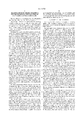
- FIGS. 1(A)-(D) show the molding method and structure of a connector block for injectors of an internal combustion engine of an embodiment of the invention, illustrating the sequential molding procedure.
- FIG. 2 is a section view taken along line I--I of FIG. 1(C);
- FIG. 3 is a section view taken along line II--II of FIG. 1(C);
- FIG. 4 is a cross section view showing a state in which a core member used in the embodiment of FIGS. 1(A)-(D) is inserted into a mold cavity;
- FIGS. 5(A)-(D) show section shapes of main portions of the injector connector block of the embodiment of FIGS. 1(A)-(D), FIG. 5(A) is a section view of a wire harness connecting portion, and FIG. 5(B), FIG. 5(C), and FIG. 5(D) are section views of injector connecting portions; and
- FIG. 6 is a section view of an injector connecting portion of an injector connector block according to another embodiment of the invention.
- a connector block 1 for injectors of an internal combustion engine includes bus bars 2 having metal members formed by a resin insert molding process.
- bus bars 2 (FIG. 1(A)) have a simple band-like shape and straight, unbent band edges arranged in parallel in such a manner that faces of adjacent bands are opposed to each other. Ends on one side of the bus bars 2 protrude to form tab-like terminals 5, thereby constituting a wire harness connecting portion 3.
- Injector connecting portions 4A, 4B, and 4C (FIG.
- each bus bar 2 in the arranged attitude is formed at the other ends and intermediate positions of the bus bars 2.
- Each bus bar 2, except the tab-like terminals 5 and the injector connecting portions 4A, 4B, and 4C, is embedded in a resin, thereby forming the bar-like connector block 1 for injectors of an internal combustion engine.
- a core member 7 (FIG. 1(B)) for accommodating the bus bars 2 in the predetermined attitude or first position is used.
- the core member 7 is inserted and held in a mold cavity 16 (FIG. 4) of a mold for resin molding, and a single step of resin injection molding is conducted to form a resin molding product of a desired shape.
- the core member 7 has a structure in which bus bar receiving portions 8A, 8B, and 8C are formed at intervals in the main column portion 10 passing through the longitudinal center of the core member 7.
- the bus bar receiving portions 8A, 8B, and 8C have bus bar slots 9 for respectively receiving the band-like bus bars 2 in such a manner that the bus bars extend in the longitudinal direction of the core member.
- the portion between the bus bar receiving portions 8A and 8B, and that between the bus bar receiving portions 8B and 8C, are configured only by the main column portion 10.
- the tab-like terminals 5 at the ends of one side of the bus bars 2 protrude from a front end of the bus bar receiving portion 8A. Only two bus bars 2 protrude in a desired length toward the back of the bus bar receiving portion 8C in the rear end, thereby constituting a bar-like body made of the resin.
- the bus bar receiving portions 8A, 8B, and 8C of the core member 7 are provided with positioning projections 11 when the core member 7 is inserted into a mold cavity 16 in a resin molding step (described later). Front half portions of holding pins 17 of the mold protrude into the mold cavity 16 and holding pin holes 12, and are fitted and oriented in such a manner that the bottoms of the holes do not reach the bus bars 2, thereby creating a separation layer 13 so that the bus bars 2 are not exposed.
- the bus bars 2 are provided with engaging projections 23 for holding the attitude of the inserted bus bars 2, and the bus bar slots 9 are provided with dimples (not shown) for receiving the engaging projections 23.
- the bus bars 2 may have dimensions under which the bus bars 2 are forcedly inserted into the bus bar slots 9, thereby holding the attitude of the bus bars 2.
- the bus bars 2 are accommodated and set in the core member 7.
- the core member 7 in the accommodated state is inserted into the mold cavity 16 formed by combining upper and lower molds 14 and 15 (see FIG. 4).
- the positioning projections 11 of the core member 7 butt against the inner wall of the mold cavity 16, and the holding pins 17 protruding from the lower mold 15 are fitted into the holding-pin holes 12 of the core member 7 so that the inserted attitude of the core member is fixed.
- a resin is injected into the space in the periphery of the core member 7 in the inserted attitude, so that the bus bars 2 are embedded in the resin 6 to form the bar-like injector connector block 1 having a desired shape.
- Holes 25 formed by the holding pins 17 are post-filled as required.
- the injector connector block 1 formed by the injection process described above has a structure in which the wire harness connecting portion 3 is formed by enclosing the tab-like terminals 5 by the resin 6.
- the portions of the core member 7 in the regions adjacent the main column portion 10 are configured as the injector connecting portions 4A, 4B, and 4C (see FIGS. 5(B), 5(C), and 5(D)), wherein intermediate and end portions of the bus bars 2 are exposed in coupling recesses 18 that open downwardly.
- Junction terminals 20 each have a first end including a bus bar contacting portion 22, and a second end including an injector contacting portion 21.
- the portions 21 and 22 are respectively formed and attached to respective ones of the exposed bus bars 2 of the injector connecting portions 4A, 4B, and 4C.
- the injector connector block 1 is pressed down against the top of a group of injectors (not shown) of an internal combustion engine to be attached thereto.
- the injector connecting portions 4A, 4B, and 4C are coupled with the respective injectors, and connectors of a wire harness are coupled with the wire harness connecting portion 3, thereby electrically connecting the injectors to the wire harness.
- the molding method of the invention and the injector connector block 1 formed by the molding method perform the above-mentioned function, and the formation can be accomplished by a single resin molding step. Therefore, the molding process can be simplified so that the cost is reduced. Moreover, the injector connector block 1 is free from a bulge portion or a protruding portion, and hence bus bars to be inserted can have a simplified shape, thereby reducing overall size and cost.
- the injector connector block 1 of the invention is not restricted to the embodiment described above.
- the injector connecting portions 4 may have a structure in which, as shown in FIG. 6, the junction terminals 20 are previously combined with the bus bars 2. Only injector connecting portions 21, which are lower portions of the junction terminals 20, are exposed in the coupling recesses 18. The bus bars 2, and the upper portions of the junction terminals 20, are embedded in the resin 6.
- the method of resin insert molding a metal member of the invention can be used not only in the formation of the above-mentioned injector connector block 1 but also in a wide variety of formations wherein plural metal members are arranged in a specified layout and then insert-molded in a resin.
- the method of resin insert molding a metal member of the invention plural metal members can be insert-molded in a resin while specifying their arranged attitude by a single step of injection molding using a mold for resin molding. Therefore, the molding process can be simplified so that the moldability is improved and the molding cost is reduced.
- the connector block for injectors of an internal combustion engine of the invention which is produced by the molding method, can attain the above-mentioned effects of improved moldability and reduced molding cost.
- Other advantages and effects are that the bus bars can have a simple shape and hence the overall structure can be simplified and reduced in size, thereby further promoting miniaturization of the connector block and reduction of cost.
Landscapes
- Engineering & Computer Science (AREA)
- Mechanical Engineering (AREA)
- Chemical & Material Sciences (AREA)
- Combustion & Propulsion (AREA)
- General Engineering & Computer Science (AREA)
- Manufacturing & Machinery (AREA)
- Composite Materials (AREA)
- Fuel-Injection Apparatus (AREA)
- Injection Moulding Of Plastics Or The Like (AREA)
- Moulds For Moulding Plastics Or The Like (AREA)
Abstract
A connector block for injectors of an internal combustion engine having a bar-like body in which bar-like bus bars are arranged in a parallel attitude and embedded in resin. A core member includes bus bar slots in which the bus bars are placed in a desired attitude. Projections are positioned such that they butt against the inner wall of a mold cavity of a mold for resin molding. Holding-pin holes into which holding pins of the mold cavity are fitted so as to form a separation layer between the bus bars and the holding pins. The assembled core member is inserted into the mold cavity of the mold for resin molding, to be held thereby, and the core member is embedded in a resin to form a desired shape.
Description
This is a Division of application Ser. No. 08/338,854 filed Nov. 14, 1994, now U.S. Pat. No. 5,709,559.
The invention relates to a method of resin insert molding a metal member, such as an electrical component for an automobile. The invention also relates to a connector block for injectors of an internal combustion engine, in which a metal member such as an electric conductor is embedded in a resin. The connector block can be produced by the resin insert molding method.
Molded products made of multiple materials, which may include, for example, metal members inserted into a resin, are injection molded using a process in which the metal members are held in a desired attitude in a mold cavity of a mold for resin molding. Each metal member inserted into the mold cavity is fixed by holding pins. protruding into the mold cavity, which leaves holding pin holes that communicate with the metal member after the mold is removed. Even if the holes are filled after the resin molding process, the post-filled portions are not sufficiently waterproof and airtight. As a result, this technique may cause corrosion of the metal member. In addition, when the metal member is used as an electric conductor, electric failure may occur.
A molding method for eliminating these disadvantages has been proposed in Japanese Patent Publication (Kokai) No. HEI4-263913. In the proposed method, a bus bar bundle, which has bus bars arranged in a desired manner, is partially embedded and held, and a preformed portion having leftover holding pin holes is primarily formed by resin molding. The bus bar bundle with the preformed portion is then inserted into a mold cavity of a mold for resin molding, and the inserted attitude is fixed by fitting holding pins of the mold into the holding pin holes of the preformed portion. Secondary processing is conducted so that the bus bar bundle with the preformed portion is embedded in a resin to form a desired form.
On the other hand, Japanese Utility Model Publication (Kokai) No. HEI3-77062, and Japanese Patent Publication (Kokai) No. HEI4-263913 disclose connector blocks for injectors of an internal combustion engine in which connecting ends are formed by vertically bending bus bars to form tip ends that rise from the bus bar main portions and function as tab terminals. Each of the bus bars, except the tab terminals, is embedded in a resin so that the tab terminals are formed as an injector connecting portion protruding from the main portion.
Although the molding methods described above have the advantages that the bus bars embedded in the resin are prevented from being corroded and electrically short-circuited, one method requires complex bus bar shapes and a plurality of steps to resin-mold the insert, and the other method requires primary molding for providing the preformed portion and secondary molding for producing the desired final resin molding product. Therefore, the operation is cumbersome so that the molding productivity is poor and molding costs are high.
The prior art connector block for injectors of an internal combustion engine has several drawbacks. For example, the shape of the bus bars for forming the injector connecting portion is complex and hence requires a great deal of manufacturing time, which increases the cost. The configuration in which the injector connection portion protrudes from the main portion (having a bar-like shape) increases the size of the connector block. From a qualitative viewpoint of preventing the bus bar from being corroded and electrically short-circuiting, the prior art methods require resin-molding according to primary and secondary molding steps, thereby inevitably further increasing the cost.
One object of the invention is to provide a molding method, and a connector block for injectors of an internal combustion engine that can eliminate the above-discussed disadvantages.
In a first aspect of the present invention, there is provided a method for insert molding a connector having metal members embedded in a resin. The metal members are inserted into a mold cavity of a mold for resin molding. The mold has holding pins protruding therefrom. The method includes placing the metal members in a molding position by inserting the metal members within slots of a core, the metal members and the core forming a molding assembly; inserting the molding assembly into the mold cavity while fitting front half portions of the holding pins into holding pin holes of the core, the holding pin holes being positioned to create a separation layer between surfaces of the holding pin holes and the metal members, the core having positioning projections butting against an inner wall of the mold cavity; and injecting the resin into the mold cavity.
In a second aspect of the present invention, there is provided a method for molding a connector having a bar-like shape, the connector including a resin, at least one metal band and a core member. The method includes placing the metal band within a slot provided on the core member to form a molding assembly; inserting the molding assembly within a mold cavity of a mold; and injecting the resin into the mold cavity to form the bar-like shape.
According to another aspect of the present invention, there is provided a connector block for injectors of an internal combustion engine. The connector block includes a bar-like body having a core member embedded in a resin. The core member accommodates bus bars each having a band-like shape and the bus bars are arranged in parallel to each-other. Also provided is a wire harness connecting portion formed at one end of said bar-like body such that the bus bars have tip ends exposed in the connecting portion. Injector connecting portions are provided for connecting the bus bars through junction terminals to injectors of an internal combustion engine. The injector connecting portions are formed at a plurality of positions on the bar-like body. The connector block for injectors may have a structure in which the bus bars are exposed in coupling recesses that open downward to allow junction terminals to be attached to the exposed bus bars. The bus bars are electrically connected through the junction terminals to the injectors of the internal combustion engine.
In still another aspect of the present invention, there is provided a connector block that includes a core member having a plurality of slots, a plurality of band-like metal bus bars disposed in respective ones of the slots, and a resin disposed above the slots so that the bus bars are located between the resin and the core member.
In the molding method of the invention, the bus bars are set in the core member, and the core member is inserted into and held in the mold cavity of the mold and embedded in a resin. Therefore, resin injection molding can be accomplished by a single step so that the molding process is simplified and molding productivity is improved. In a resin insert molding product of the metal member that is formed by the method, the separation layer formed by the core member is created or formed between the holding pin holes and the metal member. Therefore, contact between the metal member and air or water is completely prevented from occurring, thereby sufficiently ensuring waterproof and airtight connectors.
The connector block for injectors of an internal combustion engine, which is configured as described above, is formed by the molding method, and hence can attain the above-mentioned functions. The connector block has a structure in which the bus bars have a simple bar-like shape and are arranged in parallel with their faces opposed to each other. Intermediate and end portions of the bus bars are formed as the injector connecting portions that connect through the junction terminals to the injectors of the internal combustion engine. Moreover, the bus bars have a simple structure, thereby promoting the simplification in structure and the miniaturization of the injector connector block. Because the bus bars are simple and thus free from a complex shape, the process of forming the bus bars can be streamlined and simplified.
These and other aspects and advantages of the present invention are described in or apparent from the following detailed description of preferred embodiments.
The invention will be described in detail with reference to the following drawings, wherein:
FIGS. 1(A)-(D) show the molding method and structure of a connector block for injectors of an internal combustion engine of an embodiment of the invention, illustrating the sequential molding procedure.
FIG. 2 is a section view taken along line I--I of FIG. 1(C);
FIG. 3 is a section view taken along line II--II of FIG. 1(C);
FIG. 4 is a cross section view showing a state in which a core member used in the embodiment of FIGS. 1(A)-(D) is inserted into a mold cavity;
FIGS. 5(A)-(D) show section shapes of main portions of the injector connector block of the embodiment of FIGS. 1(A)-(D), FIG. 5(A) is a section view of a wire harness connecting portion, and FIG. 5(B), FIG. 5(C), and FIG. 5(D) are section views of injector connecting portions; and
FIG. 6 is a section view of an injector connecting portion of an injector connector block according to another embodiment of the invention.
Hereinafter, a first embodiment of the invention will be described with reference to FIGS. 1(A)-(D) showing the molding procedure, method, and structure of the connector block. A connector block 1 for injectors of an internal combustion engine includes bus bars 2 having metal members formed by a resin insert molding process. Four bus bars 2 (FIG. 1(A)) have a simple band-like shape and straight, unbent band edges arranged in parallel in such a manner that faces of adjacent bands are opposed to each other. Ends on one side of the bus bars 2 protrude to form tab-like terminals 5, thereby constituting a wire harness connecting portion 3. Injector connecting portions 4A, 4B, and 4C (FIG. 1(D)), through which the bus bars 2 in the arranged attitude are partially exposed, are formed at the other ends and intermediate positions of the bus bars 2. Each bus bar 2, except the tab-like terminals 5 and the injector connecting portions 4A, 4B, and 4C, is embedded in a resin, thereby forming the bar-like connector block 1 for injectors of an internal combustion engine. In the formation of the connector block 1, a core member 7 (FIG. 1(B)) for accommodating the bus bars 2 in the predetermined attitude or first position is used. The core member 7 is inserted and held in a mold cavity 16 (FIG. 4) of a mold for resin molding, and a single step of resin injection molding is conducted to form a resin molding product of a desired shape.
Specifically, the core member 7 has a structure in which bus bar receiving portions 8A, 8B, and 8C are formed at intervals in the main column portion 10 passing through the longitudinal center of the core member 7. The bus bar receiving portions 8A, 8B, and 8C have bus bar slots 9 for respectively receiving the band-like bus bars 2 in such a manner that the bus bars extend in the longitudinal direction of the core member. The portion between the bus bar receiving portions 8A and 8B, and that between the bus bar receiving portions 8B and 8C, are configured only by the main column portion 10. When the four bus bars 2 are inserted from the top of the bus bar slots 9, the bus bars 2 are held in the desired attitude or position in the resin insert 7. The bus bars 2 in the region of main column portion 10 are exposed (FIG. 3). The tab-like terminals 5 at the ends of one side of the bus bars 2 protrude from a front end of the bus bar receiving portion 8A. Only two bus bars 2 protrude in a desired length toward the back of the bus bar receiving portion 8C in the rear end, thereby constituting a bar-like body made of the resin.
Moreover, with reference to FIGS. 2 and 4, the bus bar receiving portions 8A, 8B, and 8C of the core member 7 are provided with positioning projections 11 when the core member 7 is inserted into a mold cavity 16 in a resin molding step (described later). Front half portions of holding pins 17 of the mold protrude into the mold cavity 16 and holding pin holes 12, and are fitted and oriented in such a manner that the bottoms of the holes do not reach the bus bars 2, thereby creating a separation layer 13 so that the bus bars 2 are not exposed.
The bus bars 2 are provided with engaging projections 23 for holding the attitude of the inserted bus bars 2, and the bus bar slots 9 are provided with dimples (not shown) for receiving the engaging projections 23. In the case where the dimples are not formed, the bus bars 2 may have dimensions under which the bus bars 2 are forcedly inserted into the bus bar slots 9, thereby holding the attitude of the bus bars 2.
The bus bars 2 are accommodated and set in the core member 7. The core member 7 in the accommodated state is inserted into the mold cavity 16 formed by combining upper and lower molds 14 and 15 (see FIG. 4). The positioning projections 11 of the core member 7 butt against the inner wall of the mold cavity 16, and the holding pins 17 protruding from the lower mold 15 are fitted into the holding-pin holes 12 of the core member 7 so that the inserted attitude of the core member is fixed. A resin is injected into the space in the periphery of the core member 7 in the inserted attitude, so that the bus bars 2 are embedded in the resin 6 to form the bar-like injector connector block 1 having a desired shape. Holes 25 formed by the holding pins 17 are post-filled as required.
With reference to FIG. 5(A), the injector connector block 1 formed by the injection process described above has a structure in which the wire harness connecting portion 3 is formed by enclosing the tab-like terminals 5 by the resin 6. The portions of the core member 7 in the regions adjacent the main column portion 10 are configured as the injector connecting portions 4A, 4B, and 4C (see FIGS. 5(B), 5(C), and 5(D)), wherein intermediate and end portions of the bus bars 2 are exposed in coupling recesses 18 that open downwardly. Junction terminals 20 each have a first end including a bus bar contacting portion 22, and a second end including an injector contacting portion 21. The portions 21 and 22 are respectively formed and attached to respective ones of the exposed bus bars 2 of the injector connecting portions 4A, 4B, and 4C. The injector connector block 1 is pressed down against the top of a group of injectors (not shown) of an internal combustion engine to be attached thereto. The injector connecting portions 4A, 4B, and 4C are coupled with the respective injectors, and connectors of a wire harness are coupled with the wire harness connecting portion 3, thereby electrically connecting the injectors to the wire harness.
The molding method of the invention and the injector connector block 1 formed by the molding method perform the above-mentioned function, and the formation can be accomplished by a single resin molding step. Therefore, the molding process can be simplified so that the cost is reduced. Moreover, the injector connector block 1 is free from a bulge portion or a protruding portion, and hence bus bars to be inserted can have a simplified shape, thereby reducing overall size and cost.
The injector connector block 1 of the invention is not restricted to the embodiment described above. For example, the injector connecting portions 4 may have a structure in which, as shown in FIG. 6, the junction terminals 20 are previously combined with the bus bars 2. Only injector connecting portions 21, which are lower portions of the junction terminals 20, are exposed in the coupling recesses 18. The bus bars 2, and the upper portions of the junction terminals 20, are embedded in the resin 6. The method of resin insert molding a metal member of the invention can be used not only in the formation of the above-mentioned injector connector block 1 but also in a wide variety of formations wherein plural metal members are arranged in a specified layout and then insert-molded in a resin.
As described above, according to the method of resin insert molding a metal member of the invention, plural metal members can be insert-molded in a resin while specifying their arranged attitude by a single step of injection molding using a mold for resin molding. Therefore, the molding process can be simplified so that the moldability is improved and the molding cost is reduced. The connector block for injectors of an internal combustion engine of the invention, which is produced by the molding method, can attain the above-mentioned effects of improved moldability and reduced molding cost. Other advantages and effects are that the bus bars can have a simple shape and hence the overall structure can be simplified and reduced in size, thereby further promoting miniaturization of the connector block and reduction of cost.
The invention has been described in detail with reference to preferred embodiments thereof, which are intended to be illustrative and not limiting. Various modifications can be made without departing from the spirit and scope of the invention as defined in the appended claims.
Claims (12)
1. A method for insert molding a connector having at least one metal member, said method comprising the steps of:
providing a core having a plurality of slots;
placing the at least one metal member in a molding position by inserting the at least one metal member within a corresponding slot of the core, the at least one metal member and the core forming a molding assembly;
inserting the molding assembly into a mold cavity formed of a separable mold by fitting portions of holding pins extending from a mold surface into the mold cavity into holding pin holes formed in the core, the holding pin holes being positioned to create a separation layer between surfaces of the holding pin holes and the metal members, the core having positioning projections butting against an inner wall of the mold cavity;
injecting the resin into the mold cavity around the molding assembly to form the connector; and
separating the mold to free the connector.
2. A method for molding a connector having a bar shape, said connector including a resin, at least one metal band and a core member, the method comprising:
providing the core member with a plurality of slots;
placing the at least one metal band within a corresponding slot provided in one surface of the core member to form a molding assembly;
inserting the molding assembly within a mold cavity of a mold;
injecting the resin into the mold cavity to enclose the molding assembly and form the connector; and
removing the connector from the mold.
3. The method of claim 2, wherein the inserting includes inserting at least one holding pin formed on the mold and extending into the mold cavity into a corresponding holding pin recess formed on the core member, and abutting at least one positioning protrusion formed on the core member against an inner surface of said mold, said positioning protrusion forming a space between the metal band and said inner surface of said mold, said resin being injected into and filling said space, wherein the holding pin recess is oriented to create a separation layer between the metal band and surfaces of the holding pin recess.
4. The method of claim 2, wherein the placing includes placing a junction terminal as well as said metal band in said core member to form said molding assembly.
5. The method of claim 4, further comprising connecting the metal band, through said junction terminal, with an injector of an internal combustion engine.
6. A method for molding a connector, comprising:
mounting at least one bus bar in a preformed core, the preformed core having a retention channel for each bus bar of the at least one bus bar to form a molding assembly, a surface of the core, opposite a surface having the at least one retention channel, having at least one holding pin hole;
mounting the molding assembly to a first mold by mating the at least one holding pin hole with a corresponding holding pin extending from the first mold, the mounting providing a separation between the molding assembly and the first mold;
joining a second mold to the first mold to define a cavity retaining the molding assembly therein, the second mold having a spacing from the molding assembly;
injecting resin into the cavity; and
removing the first mold and second mold to free the connector so formed, wherein the at least one retention channel and the at least one holding pin hole are separated from one another with a portion of the core therebetween.
7. The method according to claim 6, wherein a protrusion extending from the core contacts a surface of the second mold to define the spacing.
8. The method according to claim 6, further comprising attaching a junction terminal to the at least one bus bar.
9. The method according to claim 8, wherein the step of attaching a junction terminal is executed prior to the step of mounting the molding assembly to a lower mold.
10. The method according to claim 8, wherein the step of attaching a junction terminal is executed after the step of removing the first mold and the second mold.
11. A method for molding a connector block having an elongate body for injectors of an internal combustion engine, comprising the steps of:
providing a core member that extends along at least a majority of the length of the elongate body, said core member having a plurality of slots;
seating a plurality of band-shaped bus bars in the plurality of slots, said plurality of bus bars being arranged parallel to one another;
embedding said core member in a resin;
forming a wire harness connecting portion at one end of the elongate body, said plurality of bus bars having tip ends exposed in said connecting portion; and
forming injector connecting portions at a plurality of positions on the elongate body for connecting said bus bars through junction terminals located at said injector connecting portions to injectors of an internal combustion engine.
12. A method for molding a connector block having an elongate body for injectors of an internal combustion engine, comprising the steps of:
providing a core member having a plurality of slots;
accommodating band-shaped bus bars in said plurality of slots, said bus bars being arranged parallel to one another;
embedding said core member in a resin, the resin disposed above said slots and molded over the bus bars so that at least a majority of continuous length of the bus bars is located between the resin and the core member;
forming a wire harness connecting portion at one end of said elongate body, said bus bars having tip ends exposed in said connecting portion; and
forming injector connecting portions at a plurality of positions on said elongate body for connecting said bus bars through junction terminals located at said injector connecting portions to injectors of an internal combustion engine.
Priority Applications (1)
| Application Number | Priority Date | Filing Date | Title |
|---|---|---|---|
| US08/941,191 US6019928A (en) | 1993-11-17 | 1997-09-30 | Method for resin insert molding a connector block for injectors of an internal combustion engine |
Applications Claiming Priority (4)
| Application Number | Priority Date | Filing Date | Title |
|---|---|---|---|
| JP5-312550 | 1993-11-17 | ||
| JP5312550A JP2853541B2 (en) | 1993-11-17 | 1993-11-17 | Method for resin insert molding of metal member and connector block for injector of internal combustion engine |
| US08/338,854 US5709559A (en) | 1993-11-17 | 1994-11-14 | Connector block for injectors of an internal combustion engine |
| US08/941,191 US6019928A (en) | 1993-11-17 | 1997-09-30 | Method for resin insert molding a connector block for injectors of an internal combustion engine |
Related Parent Applications (1)
| Application Number | Title | Priority Date | Filing Date |
|---|---|---|---|
| US08/338,854 Division US5709559A (en) | 1993-11-17 | 1994-11-14 | Connector block for injectors of an internal combustion engine |
Publications (1)
| Publication Number | Publication Date |
|---|---|
| US6019928A true US6019928A (en) | 2000-02-01 |
Family
ID=18030564
Family Applications (2)
| Application Number | Title | Priority Date | Filing Date |
|---|---|---|---|
| US08/338,854 Expired - Lifetime US5709559A (en) | 1993-11-17 | 1994-11-14 | Connector block for injectors of an internal combustion engine |
| US08/941,191 Expired - Lifetime US6019928A (en) | 1993-11-17 | 1997-09-30 | Method for resin insert molding a connector block for injectors of an internal combustion engine |
Family Applications Before (1)
| Application Number | Title | Priority Date | Filing Date |
|---|---|---|---|
| US08/338,854 Expired - Lifetime US5709559A (en) | 1993-11-17 | 1994-11-14 | Connector block for injectors of an internal combustion engine |
Country Status (4)
| Country | Link |
|---|---|
| US (2) | US5709559A (en) |
| EP (1) | EP0653278B1 (en) |
| JP (1) | JP2853541B2 (en) |
| DE (1) | DE69407144T2 (en) |
Cited By (16)
| Publication number | Priority date | Publication date | Assignee | Title |
|---|---|---|---|---|
| US6287502B1 (en) * | 1997-12-25 | 2001-09-11 | Yazaki Corporation | Method of manufacturing a connector |
| US6365085B2 (en) * | 1998-04-15 | 2002-04-02 | Yazaki Corporation | Method of molding circuitry using mold structure |
| US6383438B2 (en) * | 1997-09-04 | 2002-05-07 | Yazaki Corporation | Method for manufacturing insert moldings |
| US6471900B1 (en) * | 1999-03-30 | 2002-10-29 | Meioukasei Co., Ltd. | Method for fabricating a connector for an electronic circuit by terminal insert molding |
| US6527989B1 (en) * | 1999-03-02 | 2003-03-04 | Yazaki Corporation | Molded connector and method for manufacturing molded connector |
| US20030160361A1 (en) * | 2000-04-27 | 2003-08-28 | Whiteley Christopher James | Reinforced moulded article and method of producing same |
| US6612290B2 (en) | 2000-11-06 | 2003-09-02 | Autonetworks Technologies, Ltd. | Injector integrated module |
| US6664478B2 (en) * | 2000-02-12 | 2003-12-16 | Tyco Electronics Uk Ltd. | Bus bar assembly |
| US20040004306A1 (en) * | 2002-07-02 | 2004-01-08 | Adc Dsl Aystems, Inc. | Molding composite objects |
| US20040135400A1 (en) * | 2002-11-01 | 2004-07-15 | Calsonic Kansei Corporation | Cross member and manufacturing method thereof |
| US6769637B2 (en) | 2000-12-04 | 2004-08-03 | Autonetworks Technologies, Ltd. | Injector module, injector electric block body, injector main bodies to be used for the same, and ignition coil device module |
| US20080079190A1 (en) * | 2004-10-19 | 2008-04-03 | Nuclear Protection Products As | Method for manufacturing a long-term storage container |
| EP1830619A3 (en) * | 2006-03-03 | 2009-08-19 | Pollmann Austria OHG | Fixing element for electric conductors, conductor structural component and method for its manufacture |
| US20110143111A1 (en) * | 2009-12-16 | 2011-06-16 | Hitachi Cable, Ltd. | Insert molding method and insert molded product |
| US20140116751A1 (en) * | 2012-10-31 | 2014-05-01 | Denso Corporation | Bus bar assembly and method of manufacturing the same |
| DE102023208529A1 (en) * | 2023-09-05 | 2025-03-06 | Leoni Bordnetz-Systeme Gmbh | Method for producing an electrical wiring harness and electrical wiring harness |
Families Citing this family (26)
| Publication number | Priority date | Publication date | Assignee | Title |
|---|---|---|---|---|
| DE19546441A1 (en) * | 1995-12-13 | 1997-06-19 | Bosch Gmbh Robert | Fuel distributor |
| DE19713008C1 (en) * | 1997-03-27 | 1998-06-04 | Neumann Henneberg Wolf | Method for assembling central electrical module for road vehicle |
| JPH10272650A (en) * | 1997-03-31 | 1998-10-13 | Sumitomo Wiring Syst Ltd | Connector-affixed insert molded article and manufacture thereof |
| US6071446A (en) * | 1997-08-29 | 2000-06-06 | Lear Automotive Dearborn, Inc | Method for centering wire harness in mold |
| JPH1187011A (en) * | 1997-09-03 | 1999-03-30 | Yazaki Corp | Connector molding method |
| US6584949B1 (en) | 1999-11-16 | 2003-07-01 | International Engine Intellectual Property Company, Llc | Wire guide for electronically controlled fuel injection systems |
| JP4926340B2 (en) * | 2001-03-09 | 2012-05-09 | 行田電線株式会社 | Mold structure of cable connecting portion and molding method |
| JP3780886B2 (en) | 2001-09-07 | 2006-05-31 | トヨタ自動車株式会社 | Valve drive device for internal combustion engine |
| US7964470B2 (en) * | 2006-03-01 | 2011-06-21 | Taiwan Semiconductor Manufacturing Company, Ltd. | Flexible processing method for metal-insulator-metal capacitor formation |
| JP4720648B2 (en) * | 2006-06-29 | 2011-07-13 | 住友電装株式会社 | Manufacturing method of resin molded products |
| JP5122829B2 (en) * | 2007-02-15 | 2013-01-16 | 矢崎総業株式会社 | TRANSFER DEVICE AND MOLDED PRODUCT MANUFACTURING DEVICE EQUIPPED WITH THE TRANSFER DEVICE |
| JP4894763B2 (en) * | 2008-01-16 | 2012-03-14 | 株式会社デンソー | Plastic molded product |
| JP5151743B2 (en) | 2008-07-03 | 2013-02-27 | 住友電装株式会社 | Connector and connector manufacturing method |
| CA2745337C (en) * | 2008-12-04 | 2015-03-03 | Enphase Energy, Inc. | Mounting rail and power distribution system for use in a photovoltaic system |
| JP5446722B2 (en) * | 2009-10-26 | 2014-03-19 | 日立金属株式会社 | Busbar module manufacturing method and busbar module |
| JP5549491B2 (en) * | 2010-09-06 | 2014-07-16 | 日立金属株式会社 | Busbar module manufacturing method and busbar module |
| JP5707266B2 (en) * | 2011-04-14 | 2015-04-22 | 新神戸電機株式会社 | Molded bus bar manufacturing method |
| CN102935693A (en) * | 2012-11-08 | 2013-02-20 | 凡嘉科技(无锡)有限公司 | Pin connector die structure |
| JP6061136B2 (en) * | 2013-01-09 | 2017-01-18 | 日立化成株式会社 | Multi-layer molded bus bar manufacturing method |
| JP2015100917A (en) * | 2013-11-20 | 2015-06-04 | トヨタ自動車株式会社 | Insert molded article, mold for insert molded article, and method for manufacturing insert molded article |
| JP6380836B2 (en) * | 2014-07-18 | 2018-08-29 | 北川工業株式会社 | Terminal block with filter |
| JP6513043B2 (en) * | 2016-03-01 | 2019-05-15 | 本田技研工業株式会社 | Insert molded article and method of manufacturing the same |
| JP6605417B2 (en) * | 2016-08-31 | 2019-11-13 | 東海興業株式会社 | Resin molded product and manufacturing method thereof |
| DE102016223816A1 (en) * | 2016-11-30 | 2018-05-30 | Robert Bosch Gmbh | Method for producing an electrical or mechanical element |
| JP7321651B2 (en) * | 2019-11-19 | 2023-08-07 | ホシデン株式会社 | WATERPROOF CABLE, WATERPROOF CABLE MANUFACTURING METHOD |
| CN111730805B (en) * | 2020-07-17 | 2021-01-05 | 潍坊正达实业有限公司 | Accurate positioning device for injection molding insert |
Citations (13)
| Publication number | Priority date | Publication date | Assignee | Title |
|---|---|---|---|---|
| GB1433135A (en) * | 1972-05-12 | 1976-04-22 | Permali Ltd | Moulded articles which are internally reinforced with inserts |
| US3983205A (en) * | 1971-07-30 | 1976-09-28 | The British Petroleum Company Limited | Method of molding reinforced articles |
| US4758172A (en) * | 1987-10-13 | 1988-07-19 | General Electric Company | Power distribution busway system |
| US4857003A (en) * | 1987-02-06 | 1989-08-15 | Robert Bosch Gmbh | Apparatus for electrical connection of electromagnetically actuatable fuel injection valves |
| US4988104A (en) * | 1989-04-03 | 1991-01-29 | Kunimori-Kagaku Co., Ltd. | Golf club head and process for its fabrication |
| JPH0377062A (en) * | 1989-08-18 | 1991-04-02 | Seiko Instr Inc | Apparatus for analyzing amino acid composition |
| US5100311A (en) * | 1990-09-21 | 1992-03-31 | Dana Corporation | Coil locator for mold encapsulation |
| EP0500219A1 (en) * | 1991-02-18 | 1992-08-26 | Sumitomo Wiring Systems, Ltd. | A method for producing a metal elements-resin insert; a connector block for injectors, and a method for producing the connector block |
| US5238415A (en) * | 1990-04-27 | 1993-08-24 | Robert Bosch Gmbh | Multiway connector for making common electrical contact with several electrically energizable units of internal combustion engines |
| US5295847A (en) * | 1990-01-16 | 1994-03-22 | Yazaki Corporation | Branch junction box and busbars for branch connection |
| US5295468A (en) * | 1991-05-17 | 1994-03-22 | Filterwerk Mann & Hummel Gmbh | Control strip with a compact plastic construction |
| US5347969A (en) * | 1991-03-23 | 1994-09-20 | Robert Bosch Gmbh | Contact strip for providing common electrical connection of several electrically operated fuel injection valves |
| US5471961A (en) * | 1993-09-02 | 1995-12-05 | Siemens Automotive L.P. | Electrical circuitry of a fuel rail assembly |
-
1993
- 1993-11-17 JP JP5312550A patent/JP2853541B2/en not_active Expired - Lifetime
-
1994
- 1994-11-14 US US08/338,854 patent/US5709559A/en not_active Expired - Lifetime
- 1994-11-15 DE DE69407144T patent/DE69407144T2/en not_active Expired - Fee Related
- 1994-11-15 EP EP94118054A patent/EP0653278B1/en not_active Expired - Lifetime
-
1997
- 1997-09-30 US US08/941,191 patent/US6019928A/en not_active Expired - Lifetime
Patent Citations (15)
| Publication number | Priority date | Publication date | Assignee | Title |
|---|---|---|---|---|
| US3983205A (en) * | 1971-07-30 | 1976-09-28 | The British Petroleum Company Limited | Method of molding reinforced articles |
| GB1433135A (en) * | 1972-05-12 | 1976-04-22 | Permali Ltd | Moulded articles which are internally reinforced with inserts |
| US4857003A (en) * | 1987-02-06 | 1989-08-15 | Robert Bosch Gmbh | Apparatus for electrical connection of electromagnetically actuatable fuel injection valves |
| US4758172A (en) * | 1987-10-13 | 1988-07-19 | General Electric Company | Power distribution busway system |
| US4988104A (en) * | 1989-04-03 | 1991-01-29 | Kunimori-Kagaku Co., Ltd. | Golf club head and process for its fabrication |
| JPH0377062A (en) * | 1989-08-18 | 1991-04-02 | Seiko Instr Inc | Apparatus for analyzing amino acid composition |
| US5295847A (en) * | 1990-01-16 | 1994-03-22 | Yazaki Corporation | Branch junction box and busbars for branch connection |
| US5238415A (en) * | 1990-04-27 | 1993-08-24 | Robert Bosch Gmbh | Multiway connector for making common electrical contact with several electrically energizable units of internal combustion engines |
| US5100311A (en) * | 1990-09-21 | 1992-03-31 | Dana Corporation | Coil locator for mold encapsulation |
| JPH04263913A (en) * | 1991-02-18 | 1992-09-18 | Nippondenso Co Ltd | Resin insertion molding method of metallic material |
| EP0500219A1 (en) * | 1991-02-18 | 1992-08-26 | Sumitomo Wiring Systems, Ltd. | A method for producing a metal elements-resin insert; a connector block for injectors, and a method for producing the connector block |
| US5527502A (en) * | 1991-02-18 | 1996-06-18 | Sumitomo Wiring Systems, Ltd. | Method for producing a metal elements-resin insert, a connector block for injectors, and a method for producing the connector block |
| US5347969A (en) * | 1991-03-23 | 1994-09-20 | Robert Bosch Gmbh | Contact strip for providing common electrical connection of several electrically operated fuel injection valves |
| US5295468A (en) * | 1991-05-17 | 1994-03-22 | Filterwerk Mann & Hummel Gmbh | Control strip with a compact plastic construction |
| US5471961A (en) * | 1993-09-02 | 1995-12-05 | Siemens Automotive L.P. | Electrical circuitry of a fuel rail assembly |
Cited By (22)
| Publication number | Priority date | Publication date | Assignee | Title |
|---|---|---|---|---|
| US6383438B2 (en) * | 1997-09-04 | 2002-05-07 | Yazaki Corporation | Method for manufacturing insert moldings |
| US6596946B2 (en) | 1997-09-04 | 2003-07-22 | Yazaki Corporation | Molding with integral fixation member |
| US6287502B1 (en) * | 1997-12-25 | 2001-09-11 | Yazaki Corporation | Method of manufacturing a connector |
| US6365085B2 (en) * | 1998-04-15 | 2002-04-02 | Yazaki Corporation | Method of molding circuitry using mold structure |
| US6527989B1 (en) * | 1999-03-02 | 2003-03-04 | Yazaki Corporation | Molded connector and method for manufacturing molded connector |
| US6471900B1 (en) * | 1999-03-30 | 2002-10-29 | Meioukasei Co., Ltd. | Method for fabricating a connector for an electronic circuit by terminal insert molding |
| US6664478B2 (en) * | 2000-02-12 | 2003-12-16 | Tyco Electronics Uk Ltd. | Bus bar assembly |
| US20030160361A1 (en) * | 2000-04-27 | 2003-08-28 | Whiteley Christopher James | Reinforced moulded article and method of producing same |
| US6612290B2 (en) | 2000-11-06 | 2003-09-02 | Autonetworks Technologies, Ltd. | Injector integrated module |
| US6769637B2 (en) | 2000-12-04 | 2004-08-03 | Autonetworks Technologies, Ltd. | Injector module, injector electric block body, injector main bodies to be used for the same, and ignition coil device module |
| US7118697B2 (en) * | 2002-07-02 | 2006-10-10 | Adc Dsl Systems Inc. | Method of molding composite objects |
| US20040004306A1 (en) * | 2002-07-02 | 2004-01-08 | Adc Dsl Aystems, Inc. | Molding composite objects |
| US20040135400A1 (en) * | 2002-11-01 | 2004-07-15 | Calsonic Kansei Corporation | Cross member and manufacturing method thereof |
| US7303714B2 (en) * | 2002-11-01 | 2007-12-04 | Calsonic Kansei Corporation | Cross member and manufacturing method thereof |
| US20080079190A1 (en) * | 2004-10-19 | 2008-04-03 | Nuclear Protection Products As | Method for manufacturing a long-term storage container |
| US7354544B1 (en) * | 2004-10-19 | 2008-04-08 | Nuclear Protection Products As | Method for manufacturing a long-term storage container |
| EP1830619A3 (en) * | 2006-03-03 | 2009-08-19 | Pollmann Austria OHG | Fixing element for electric conductors, conductor structural component and method for its manufacture |
| US20110143111A1 (en) * | 2009-12-16 | 2011-06-16 | Hitachi Cable, Ltd. | Insert molding method and insert molded product |
| US8540917B2 (en) * | 2009-12-16 | 2013-09-24 | Hitachi Cable, Ltd. | Insert molding method and insert molded product |
| US20140116751A1 (en) * | 2012-10-31 | 2014-05-01 | Denso Corporation | Bus bar assembly and method of manufacturing the same |
| US9302435B2 (en) * | 2012-10-31 | 2016-04-05 | Denso Corporation | Bus bar assembly and method of manufacturing the same |
| DE102023208529A1 (en) * | 2023-09-05 | 2025-03-06 | Leoni Bordnetz-Systeme Gmbh | Method for producing an electrical wiring harness and electrical wiring harness |
Also Published As
| Publication number | Publication date |
|---|---|
| EP0653278A1 (en) | 1995-05-17 |
| JP2853541B2 (en) | 1999-02-03 |
| DE69407144T2 (en) | 1998-04-23 |
| JPH07137090A (en) | 1995-05-30 |
| DE69407144D1 (en) | 1998-01-15 |
| US5709559A (en) | 1998-01-20 |
| EP0653278B1 (en) | 1997-12-03 |
Similar Documents
| Publication | Publication Date | Title |
|---|---|---|
| US6019928A (en) | Method for resin insert molding a connector block for injectors of an internal combustion engine | |
| EP0853356B1 (en) | A connector producing method and a connector produced by insert molding and a use thereof | |
| US6048482A (en) | Method for manufacturing an electrical connector | |
| EP1109253B1 (en) | Cable wafer connector with integrated strain relief | |
| JP3078860B2 (en) | Resin insert molding method for metal members | |
| US4269467A (en) | Electrical connector receptacle having molded conductors | |
| JP4153053B2 (en) | Strip with electrical or mechanical parts and method for manufacturing the same | |
| US6076258A (en) | Method for insert molding and method for producing a connector | |
| JPH0154824B2 (en) | ||
| US3618207A (en) | Method of manufacturing strip connectors | |
| US6893295B1 (en) | Connector with integrated strain relief | |
| US4495130A (en) | Method of molding an electrical connector | |
| US7370413B2 (en) | Method of making an electrical connector | |
| US20040253871A1 (en) | Waterproof construction for a ground terminal fitting, a method and an apparatus for waterproofing a ground terminal fitting | |
| JP2000012170A (en) | Connector for apparatus and manufacture of same | |
| EP1351346B1 (en) | Joint connector for wire harness | |
| US6371816B1 (en) | Electric connector and a method of making same | |
| JP2000507384A (en) | High density electrical connector | |
| US6083039A (en) | Connector contact mold-positioning | |
| JP4197388B2 (en) | Production method of insert molded parts | |
| JPH1131572A (en) | Method of manufacturing connector and connector | |
| JP3405893B2 (en) | Valve socket plug and manufacturing method thereof | |
| JP5172616B2 (en) | connector | |
| JP3027923B2 (en) | Method of molding connector block for injector and bus bar and core member used therefor | |
| JP3623136B2 (en) | Insert molding method |
Legal Events
| Date | Code | Title | Description |
|---|---|---|---|
| FEPP | Fee payment procedure |
Free format text: PAYOR NUMBER ASSIGNED (ORIGINAL EVENT CODE: ASPN); ENTITY STATUS OF PATENT OWNER: LARGE ENTITY |
|
| STCF | Information on status: patent grant |
Free format text: PATENTED CASE |
|
| FPAY | Fee payment |
Year of fee payment: 4 |
|
| FPAY | Fee payment |
Year of fee payment: 8 |
|
| FPAY | Fee payment |
Year of fee payment: 12 |