US5996944A - Trough having compartments for securing cables and wires - Google Patents
Trough having compartments for securing cables and wires Download PDFInfo
- Publication number
- US5996944A US5996944A US09/143,205 US14320598A US5996944A US 5996944 A US5996944 A US 5996944A US 14320598 A US14320598 A US 14320598A US 5996944 A US5996944 A US 5996944A
- Authority
- US
- United States
- Prior art keywords
- wires
- cables
- arm
- arms
- base
- Prior art date
- Legal status (The legal status is an assumption and is not a legal conclusion. Google has not performed a legal analysis and makes no representation as to the accuracy of the status listed.)
- Expired - Fee Related
Links
Images


Classifications
-
- F—MECHANICAL ENGINEERING; LIGHTING; HEATING; WEAPONS; BLASTING
- F16—ENGINEERING ELEMENTS AND UNITS; GENERAL MEASURES FOR PRODUCING AND MAINTAINING EFFECTIVE FUNCTIONING OF MACHINES OR INSTALLATIONS; THERMAL INSULATION IN GENERAL
- F16L—PIPES; JOINTS OR FITTINGS FOR PIPES; SUPPORTS FOR PIPES, CABLES OR PROTECTIVE TUBING; MEANS FOR THERMAL INSULATION IN GENERAL
- F16L3/00—Supports for pipes, cables or protective tubing, e.g. hangers, holders, clamps, cleats, clips, brackets
Definitions
- the invention relates to a device for securing and retaining cables and wires, which facilitates their identification and handling by separating different types of cables and/or wires into different compartments.
- cables and wires enter and exit a junction box; for example, telephone cables, fiber optics and wires or cables for transmission of voice data and facsimile.
- the number of cables and wires can be numerous and may result in a complex maze of cables and wires intertwined together in the area surrounding a junction box.
- Some of the cables or wires, such as fiber optics, are generally permanently connected to an end location; whereas, other cables or wires, such as copper telephone wires, require frequent servicing to interconnect or cross-connect, which involves disconnecting and re-connecting the cables or wires.
- a prior art device provides for the separation of wires by utilizing troughs.
- the prior art trough has two arms extending from a base, with the tips of each arm almost touching each other, enclosing a space between the arms with a gap between the tips of the arms.
- the prior art trough is designed for inserting wires through the gap into the space between the arms.
- the gap is designed to only fit wires through and it provides quick access to the wires.
- the prior art trough can secure and retain wires only.
- the prior art trough is designed to be snap mounted onto the surface of a telephone junction box, adjacent to the exit and entry slots of the junction box, to properly secure and retain wires exiting and entering the junction box.
- the prior art trough retains wires, it does not provide for the separation and isolation of different types of cables and wires. Both permanently connected wires and those require frequent servicing may become entangled in a prior art trough. When a service technician attempts to trace a wire for servicing, he/she may accidentally pull on the permanently connected wires and damage the wires. This is especially problematic if the wires are fiber optic lines, which are delicate and may crack at the splice or connection point.
- the invention provides a device for securing and retaining different types of cables and wires separately, which facilitates their identification and handling.
- the invention provides a trough having compartments for separately retaining and securing cables and wires to allow quick access to those cables or wires requiring frequent servicing and isolating and securing others not often requiring servicing, such as those permanently connected cables or wires.
- the trough of the present invention comprises at least two compartments, here defined as an upper and a lower compartment.
- the upper compartment comprises a base having two arms upwardly extending therefrom, one from each end of the base.
- the two arms enclose a space therebetween for retaining a first type of cables or wires.
- the tips of the two arms overlap each other in a spaced, offset position, creating a gap between the tips of the two arms where wires may be slid through the gap into the space for quick access.
- the lower compartment comprises an integral L-shaped arm and a pivotable arm downwardly extending from each end of the common base.
- the pivotal arm is provided with a locking system which maintains the pivotal arm in position and contact with the L-shaped arm to form the lower compartment.
- one end of the pivotal arm has a countersink for positioning a screw, which shank engages a mating receptacle in the L-shaped arm.
- the pivotable arm provides entry to the lower compartment for separating and isolating wires, such as those that are permanently connected to prevent mishandling.
- FIG. 1 is a front view of the present invention illustrating the upper and lower compartments.
- FIG. 2 is a top plan view illustrating the offset arms, taken along line 2--2 in FIG. 1.
- FIG. 3 is a perspective view of the present invention.
- FIG. 4 is a front view illustrating the pivotable arm in an open position.
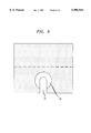
- FIG. 5 is a side view taken along line 5--5 in FIG. 4.
- FIG. 6 is a cross-sectional view of the countersink taken along line 6--6 in FIG. 4.
- FIG. 1 a front view of the present invention.
- the present invention trough 10, as shown in FIG. 1, comprises an upper compartment 20 and a lower compartment 30.
- the upper compartment 20 comprises a base 21 having a pair of arms 22 extending upwardly therefrom, one from each end of base 21.
- Arms 22 are shown to be L-shaped, but other shapes, curved or straight (not shown), is contemplated and does not detract from the spirit of the present invention.
- Enclosed between the pair of arms 22 is space 23 for securing and retaining a first type of wires or cables.
- the lower compartment 30 comprises an integral L-shaped arm 31 and a pivotable arm 32 extending downwardly from each end of common base 21.
- L-shaped arm 31 and pivotable arm 32 enclose space 33 for securing and retaining a second type of wires or cables.
- Pivotable arm 32 pivots from a closed to an open position to provide access and facilitate insertion of large cables or a large number of cables or wires into space 33, best shown in FIG. 4.
- Pivot point 34 is shown as a living hinge, but other pivotable means known to one skilled in the art may be substituted.
- pivotable arm 32 is to fixed arm 32 while adding a pivoting joint between the L-shaped arm 31 to allow the horizontal portion 31a of the L-shaped arm to pivot away from the vertical portion 31b (not shown).
- the free end 35 of pivotable arm 32 has a locking system which maintains pivotal arm 32 in contact and in position with L-shaped arm 31 to secure and isolate cables or wires in lower compartment 30.
- the locking system comprises a countersink 36 on free end 35 of pivotable arm 32, a screw 37 having a head 38 and shank 39 and a threaded receptacle 40 in L-shaped arm 31.
- Shank 39 of screw 37 is inserted through countersink 36 to engage mating receptacle 40 to lock pivotable arm 32 in position with L-shaped arm 31.
- Countersink 36 provides an open channel 41 of a predetermined width slightly larger than the diameter of shank 39 and smaller than the diameter of head 38, best shown in FIGS.
- Additional security of the locking mechanism may be provided for the lower compartment 30 by utilizing a security screw (not shown), such as those generally known to one skilled in the telephone art, wherein a special tool is necessary to disengage the security screw.
- a security screw such as those generally known to one skilled in the telephone art, wherein a special tool is necessary to disengage the security screw.
- Other methods of positive engagement of pivotable arm 32 to L-shaped arm 31 known to one skilled in the arm may be substituted, for example, a latch-hook system.
- FIG. 2 shows arms 22 extending from base 21 in an offset position.
- tips 24 of arms 22 overlap each other and spaced apart to form a gap 25 therebetween. Wires may be slid into space 23 through gap 25 and the offset and overlapping position of arms 22 prevents accidental slippage of wires from space 23. While the overlapping tips 24 are shown in a plane parallel to base 21, i.e. both tips 24 are equidistance from base 21, the overlapping tips 24 could also be in a plane that include base 21, i.e. one of the tip 24 is closer to base 21 than the other tip 24 (not shown).
- Trough 10 is adapted for use with a telephone junction box.
- a latch 42 and a hook 43 for hooking and snap mounting trough 10 onto mating units on the surface of a junction box (not shown).
- Placing trough 10 at a location adjacent to the junction box facilitates the allocation of different types of wires and/or cables entering and exiting a junction box.
- Trough 10 can also be adapted for mounting along a wall by providing at least one hole (not shown) on L-shaped arm 31 or arm 22 through which screws or nails may be driven to secure trough 10.
- other mounting methods known to one skill in the art may be used to secure trough 10 to a location where its use is contemplated.
- FIG. 3 shows a perspective view of trough 10, a better illustration of the features of the present invention.
- FIG. 4 shows pivotable arm 32 in an open position. Pivotable arm 32 provides access for cables or wires to be positioned in the second compartment 30 for separation and isolation in space 33.
- FIG. 5 is a side view of trough 10 illustrating arms 22, free end 35 of pivotable arm 32, screw 37 and mating receptacle 40 of L-shaped arm 31.
- FIG. 6 is a cross-sectional view of free end 35 of pivotable arm 32 illustrating countersink 36 having open channel 41.
- troughs having more than two compartments are contemplated, which may include a third or more compartments below the lower compartment, similar to either the upper or lower compartments 20 and 30, which corresponds to the description for a two compartment trough 10 and is not separately discussed herein.
Abstract
Description
Claims (8)
Priority Applications (1)
| Application Number | Priority Date | Filing Date | Title |
|---|---|---|---|
| US09/143,205 US5996944A (en) | 1998-08-28 | 1998-08-28 | Trough having compartments for securing cables and wires |
Applications Claiming Priority (1)
| Application Number | Priority Date | Filing Date | Title |
|---|---|---|---|
| US09/143,205 US5996944A (en) | 1998-08-28 | 1998-08-28 | Trough having compartments for securing cables and wires |
Publications (1)
| Publication Number | Publication Date |
|---|---|
| US5996944A true US5996944A (en) | 1999-12-07 |
Family
ID=22503057
Family Applications (1)
| Application Number | Title | Priority Date | Filing Date |
|---|---|---|---|
| US09/143,205 Expired - Fee Related US5996944A (en) | 1998-08-28 | 1998-08-28 | Trough having compartments for securing cables and wires |
Country Status (1)
| Country | Link |
|---|---|
| US (1) | US5996944A (en) |
Cited By (6)
| Publication number | Priority date | Publication date | Assignee | Title |
|---|---|---|---|---|
| US6370246B1 (en) * | 1998-08-28 | 2002-04-09 | Avaya Technology Corp. | Trough for cables and wires |
| US6388196B1 (en) * | 1999-10-20 | 2002-05-14 | Delta Electronics, Inc. | Fan wire collection structure |
| US6427952B2 (en) * | 1999-12-15 | 2002-08-06 | Panduit Corp. | Cable management ring |
| US6559382B2 (en) | 2001-05-15 | 2003-05-06 | Lucent Technologies Inc. | Fiber optic guides with integrated security |
| US6613981B1 (en) * | 2001-10-17 | 2003-09-02 | Chatsworth Products, Inc. | Pivotable cable ring wire management system |
| US11448843B2 (en) * | 2014-09-16 | 2022-09-20 | CommScope Connectivity Belgium BVBA | Rotatable patch cable holder |
Citations (4)
| Publication number | Priority date | Publication date | Assignee | Title |
|---|---|---|---|---|
| US4845316A (en) * | 1986-08-20 | 1989-07-04 | Hewlett-Packard Company | Strain relieving device in combination with electrical cables |
| US5669590A (en) * | 1995-12-04 | 1997-09-23 | Yazaki Corporation | Retaining clip with multiple clamps |
| US5868362A (en) * | 1997-08-29 | 1999-02-09 | Lucent Technologies Inc. | Latching mechanism for back-to-back mounting |
| US5884372A (en) * | 1997-08-04 | 1999-03-23 | National Molding Corporation | Refreshment tube retaining device |
-
1998
- 1998-08-28 US US09/143,205 patent/US5996944A/en not_active Expired - Fee Related
Patent Citations (4)
| Publication number | Priority date | Publication date | Assignee | Title |
|---|---|---|---|---|
| US4845316A (en) * | 1986-08-20 | 1989-07-04 | Hewlett-Packard Company | Strain relieving device in combination with electrical cables |
| US5669590A (en) * | 1995-12-04 | 1997-09-23 | Yazaki Corporation | Retaining clip with multiple clamps |
| US5884372A (en) * | 1997-08-04 | 1999-03-23 | National Molding Corporation | Refreshment tube retaining device |
| US5868362A (en) * | 1997-08-29 | 1999-02-09 | Lucent Technologies Inc. | Latching mechanism for back-to-back mounting |
Cited By (6)
| Publication number | Priority date | Publication date | Assignee | Title |
|---|---|---|---|---|
| US6370246B1 (en) * | 1998-08-28 | 2002-04-09 | Avaya Technology Corp. | Trough for cables and wires |
| US6388196B1 (en) * | 1999-10-20 | 2002-05-14 | Delta Electronics, Inc. | Fan wire collection structure |
| US6427952B2 (en) * | 1999-12-15 | 2002-08-06 | Panduit Corp. | Cable management ring |
| US6559382B2 (en) | 2001-05-15 | 2003-05-06 | Lucent Technologies Inc. | Fiber optic guides with integrated security |
| US6613981B1 (en) * | 2001-10-17 | 2003-09-02 | Chatsworth Products, Inc. | Pivotable cable ring wire management system |
| US11448843B2 (en) * | 2014-09-16 | 2022-09-20 | CommScope Connectivity Belgium BVBA | Rotatable patch cable holder |
Similar Documents
| Publication | Publication Date | Title |
|---|---|---|
| US7829797B2 (en) | Three channel raceway | |
| US5947765A (en) | Multimedia outlet | |
| US5898129A (en) | Rack mountable cable distribution enclosure | |
| US5645449A (en) | Low profile mixed media information outlet | |
| US5902961A (en) | Cable manager | |
| US5538438A (en) | RJ connector and cover therefor | |
| US20020142650A1 (en) | Multimedia outlet with protective cover | |
| KR100326742B1 (en) | Multiple Contact Pin Holder for Weak Current Installations | |
| US20030016931A1 (en) | Cable trough cover | |
| US6340317B1 (en) | Hinged wiring block | |
| EP1780832A2 (en) | Enclosure | |
| US20060068633A1 (en) | Work station outlet for behind-the-wall cable management | |
| US5996944A (en) | Trough having compartments for securing cables and wires | |
| US11862950B2 (en) | Cable duct assembly | |
| US5370541A (en) | Repositionable termination module | |
| US7123716B2 (en) | Headset cable retainer | |
| US6676430B1 (en) | Board mounted jack module | |
| US6370246B1 (en) | Trough for cables and wires | |
| US6358080B1 (en) | Snap-in module system | |
| US6332795B1 (en) | Hinged connection system | |
| US20110217857A1 (en) | Cradle for fastening a terminal block to a mounting frame and arrangement for earthing a terminal block | |
| US6036040A (en) | Positive-retention wire trough for electrical equipment | |
| US6250954B1 (en) | Electrical connection box | |
| JP4602447B2 (en) | Retention member, mounting member, mounting base for optical wiring board, optical wiring board | |
| US20030134535A1 (en) | Electrical connector termination tool |
Legal Events
| Date | Code | Title | Description |
|---|---|---|---|
| AS | Assignment |
Owner name: LUCENT TECHNOLOGIES, INC., NEW JERSEY Free format text: ASSIGNMENT OF ASSIGNORS INTEREST;ASSIGNOR:DAOUD, BASSEL HAGE;REEL/FRAME:009429/0958 Effective date: 19980827 |
|
| FEPP | Fee payment procedure |
Free format text: PAYOR NUMBER ASSIGNED (ORIGINAL EVENT CODE: ASPN); ENTITY STATUS OF PATENT OWNER: LARGE ENTITY |
|
| AS | Assignment |
Owner name: AVAYA TECHNOLOGY CORP., NEW JERSEY Free format text: ASSIGNMENT OF ASSIGNORS INTEREST;ASSIGNOR:LUCENT TECHNOLOGIES INC.;REEL/FRAME:012691/0572 Effective date: 20000929 |
|
| AS | Assignment |
Owner name: BANK OF NEW YORK, THE, NEW YORK Free format text: SECURITY AGREEMENT;ASSIGNOR:AVAYA TECHNOLOGY CORP.;REEL/FRAME:012762/0177 Effective date: 20020405 |
|
| REMI | Maintenance fee reminder mailed | ||
| FPAY | Fee payment |
Year of fee payment: 4 |
|
| SULP | Surcharge for late payment | ||
| FPAY | Fee payment |
Year of fee payment: 8 |
|
| AS | Assignment |
Owner name: AVAYA TECHNOLOGY CORPORATION, NEW JERSEY Free format text: RELEASE BY SECURED PARTY;ASSIGNOR:THE BANK OF NEW YORK;REEL/FRAME:019881/0532 Effective date: 20040101 |
|
| AS | Assignment |
Owner name: COMMSCOPE SOLUTIONS PROPERTIES, LLC, NEVADA Free format text: ASSIGNMENT OF ASSIGNORS INTEREST;ASSIGNOR:AVAYA TECHNOLOGY CORPORATION;REEL/FRAME:019984/0094 Effective date: 20040129 |
|
| AS | Assignment |
Owner name: COMMSCOPE, INC. OF NORTH CAROLINA, NORTH CAROLINA Free format text: MERGER;ASSIGNOR:COMMSCOPE SOLUTIONS PROPERTIES, LLC;REEL/FRAME:019991/0643 Effective date: 20061220 Owner name: COMMSCOPE, INC. OF NORTH CAROLINA,NORTH CAROLINA Free format text: MERGER;ASSIGNOR:COMMSCOPE SOLUTIONS PROPERTIES, LLC;REEL/FRAME:019991/0643 Effective date: 20061220 |
|
| AS | Assignment |
Owner name: BANK OF AMERICA, N.A., AS ADMINISTRATIVE AGENT, CA Free format text: SECURITY AGREEMENT;ASSIGNORS:COMMSCOPE, INC. OF NORTH CAROLINA;ALLEN TELECOM, LLC;ANDREW CORPORATION;REEL/FRAME:020362/0241 Effective date: 20071227 Owner name: BANK OF AMERICA, N.A., AS ADMINISTRATIVE AGENT,CAL Free format text: SECURITY AGREEMENT;ASSIGNORS:COMMSCOPE, INC. OF NORTH CAROLINA;ALLEN TELECOM, LLC;ANDREW CORPORATION;REEL/FRAME:020362/0241 Effective date: 20071227 |
|
| AS | Assignment |
Owner name: ALLEN TELECOM LLC, NORTH CAROLINA Free format text: PATENT RELEASE;ASSIGNOR:BANK OF AMERICA, N.A., AS ADMINISTRATIVE AGENT;REEL/FRAME:026039/0005 Effective date: 20110114 Owner name: COMMSCOPE, INC. OF NORTH CAROLINA, NORTH CAROLINA Free format text: PATENT RELEASE;ASSIGNOR:BANK OF AMERICA, N.A., AS ADMINISTRATIVE AGENT;REEL/FRAME:026039/0005 Effective date: 20110114 Owner name: ANDREW LLC (F/K/A ANDREW CORPORATION), NORTH CAROL Free format text: PATENT RELEASE;ASSIGNOR:BANK OF AMERICA, N.A., AS ADMINISTRATIVE AGENT;REEL/FRAME:026039/0005 Effective date: 20110114 |
|
| AS | Assignment |
Owner name: JPMORGAN CHASE BANK, N.A., AS COLLATERAL AGENT, NE Free format text: SECURITY AGREEMENT;ASSIGNORS:ALLEN TELECOM LLC, A DELAWARE LLC;ANDREW LLC, A DELAWARE LLC;COMMSCOPE, INC. OF NORTH CAROLINA, A NORTH CAROLINA CORPORATION;REEL/FRAME:026276/0363 Effective date: 20110114 |
|
| AS | Assignment |
Owner name: JPMORGAN CHASE BANK, N.A., AS COLLATERAL AGENT, NE Free format text: SECURITY AGREEMENT;ASSIGNORS:ALLEN TELECOM LLC, A DELAWARE LLC;ANDREW LLC, A DELAWARE LLC;COMMSCOPE, INC OF NORTH CAROLINA, A NORTH CAROLINA CORPORATION;REEL/FRAME:026272/0543 Effective date: 20110114 |
|
| REMI | Maintenance fee reminder mailed | ||
| LAPS | Lapse for failure to pay maintenance fees | ||
| LAPS | Lapse for failure to pay maintenance fees |
Free format text: PATENT EXPIRED FOR FAILURE TO PAY MAINTENANCE FEES (ORIGINAL EVENT CODE: EXP.); ENTITY STATUS OF PATENT OWNER: LARGE ENTITY |
|
| STCH | Information on status: patent discontinuation |
Free format text: PATENT EXPIRED DUE TO NONPAYMENT OF MAINTENANCE FEES UNDER 37 CFR 1.362 |
|
| FP | Lapsed due to failure to pay maintenance fee |
Effective date: 20111207 |
|
| AS | Assignment |
Owner name: AVAYA INC. (FORMERLY KNOWN AS AVAYA TECHNOLOGY COR Free format text: BANKRUPTCY COURT ORDER RELEASING ALL LIENS INCLUDING THE SECURITY INTEREST RECORDED AT REEL/FRAME 012762/0177;ASSIGNOR:THE BANK OF NEW YORK;REEL/FRAME:044893/0088 Effective date: 20171128 |
|
| AS | Assignment |
Owner name: ALLEN TELECOM LLC, ILLINOIS Free format text: RELEASE BY SECURED PARTY;ASSIGNOR:JPMORGAN CHASE BANK, N.A.;REEL/FRAME:048840/0001 Effective date: 20190404 Owner name: REDWOOD SYSTEMS, INC., NORTH CAROLINA Free format text: RELEASE BY SECURED PARTY;ASSIGNOR:JPMORGAN CHASE BANK, N.A.;REEL/FRAME:048840/0001 Effective date: 20190404 Owner name: COMMSCOPE TECHNOLOGIES LLC, NORTH CAROLINA Free format text: RELEASE BY SECURED PARTY;ASSIGNOR:JPMORGAN CHASE BANK, N.A.;REEL/FRAME:048840/0001 Effective date: 20190404 Owner name: COMMSCOPE, INC. OF NORTH CAROLINA, NORTH CAROLINA Free format text: RELEASE BY SECURED PARTY;ASSIGNOR:JPMORGAN CHASE BANK, N.A.;REEL/FRAME:048840/0001 Effective date: 20190404 Owner name: ANDREW LLC, NORTH CAROLINA Free format text: RELEASE BY SECURED PARTY;ASSIGNOR:JPMORGAN CHASE BANK, N.A.;REEL/FRAME:048840/0001 Effective date: 20190404 Owner name: ANDREW LLC, NORTH CAROLINA Free format text: RELEASE BY SECURED PARTY;ASSIGNOR:JPMORGAN CHASE BANK, N.A.;REEL/FRAME:049260/0001 Effective date: 20190404 Owner name: REDWOOD SYSTEMS, INC., NORTH CAROLINA Free format text: RELEASE BY SECURED PARTY;ASSIGNOR:JPMORGAN CHASE BANK, N.A.;REEL/FRAME:049260/0001 Effective date: 20190404 Owner name: ALLEN TELECOM LLC, ILLINOIS Free format text: RELEASE BY SECURED PARTY;ASSIGNOR:JPMORGAN CHASE BANK, N.A.;REEL/FRAME:049260/0001 Effective date: 20190404 Owner name: COMMSCOPE TECHNOLOGIES LLC, NORTH CAROLINA Free format text: RELEASE BY SECURED PARTY;ASSIGNOR:JPMORGAN CHASE BANK, N.A.;REEL/FRAME:049260/0001 Effective date: 20190404 Owner name: COMMSCOPE, INC. OF NORTH CAROLINA, NORTH CAROLINA Free format text: RELEASE BY SECURED PARTY;ASSIGNOR:JPMORGAN CHASE BANK, N.A.;REEL/FRAME:049260/0001 Effective date: 20190404 |