US598564A - Metallic bedstead - Google Patents
Metallic bedstead Download PDFInfo
- Publication number
- US598564A US598564A US598564DA US598564A US 598564 A US598564 A US 598564A US 598564D A US598564D A US 598564DA US 598564 A US598564 A US 598564A
- Authority
- US
- United States
- Prior art keywords
- end rail
- bed
- curved
- outwardly
- corner
- Prior art date
- Legal status (The legal status is an assumption and is not a legal conclusion. Google has not performed a legal analysis and makes no representation as to the accuracy of the status listed.)
- Expired - Lifetime
Links
- 238000007665 sagging Methods 0.000 description 3
- 238000005266 casting Methods 0.000 description 2
- 238000010276 construction Methods 0.000 description 1
- 239000000463 material Substances 0.000 description 1
- 230000004048 modification Effects 0.000 description 1
- 238000012986 modification Methods 0.000 description 1
- 239000011435 rock Substances 0.000 description 1
Images

Classifications
-
- F—MECHANICAL ENGINEERING; LIGHTING; HEATING; WEAPONS; BLASTING
- F16—ENGINEERING ELEMENTS AND UNITS; GENERAL MEASURES FOR PRODUCING AND MAINTAINING EFFECTIVE FUNCTIONING OF MACHINES OR INSTALLATIONS; THERMAL INSULATION IN GENERAL
- F16B—DEVICES FOR FASTENING OR SECURING CONSTRUCTIONAL ELEMENTS OR MACHINE PARTS TOGETHER, e.g. NAILS, BOLTS, CIRCLIPS, CLAMPS, CLIPS OR WEDGES; JOINTS OR JOINTING
- F16B12/00—Jointing of furniture or the like, e.g. hidden from exterior
- F16B12/54—Fittings for bedsteads or the like
- F16B12/58—Tapered connectors for bed rails
Definitions
- Bedbottoms made. of wire or equivalent material have a tendency to sag at the middle, where they are subjected to the greatest strain, and to compensate for such sagging one of the end rails to which the bed-bottom is attached has been curved upwardly or arched.
- arching the end rail but partially compensates for sagging; but I have found that by curving such end rail outwardly,'-as well as upwardly, the bed-bottom may be hung so that when in use it will lie substantiallyflat.
- the strain upon it causes it to rock or tilt and soon loosens its end connections with the parts supporting it, and hence some means must be provided for holding it in fixed position.
- the strain upon it springs it, and thereby soon loosens the end connections, so that even with such form of end rail some means must be provided for holding it in fixed position.
- I provide the end rail with a suitable stay arranged vertically and connected to the main framework at two points and either passing throughor connected to said end rail.
- Figure 1 shows an end view of a bed-frame provided with an upwardly and outwardly curved end rail and stay therefor embodying this invention
- Fig. 2 a vertical section of the parts shown in Fig; 1, taken on the dotted line w a;
- Fig. 3 an end ,view of a bed-frame having an upwardly and outwardly curved end rail and a modified form of stay therefor;
- Fig. 4 a vertical section of the parts shown in Fig. 3, taken on the dotted line y y;
- Fig. 5 a perspective detail showing the end rail and stay therefor and casting or support to which the end rail is connected;
- Fig. 6, avertical section of a bed-frame having a straight end rail and stay therefor;
- Fig. 7 a vertical 'sec tion of a bed-frame having an upwardlycurved end rail and stay therefor;
- Fig. 8 a vertical section of a bed-frame having an outwardly-curved end rail and a stay therefor;
- Fig. 9, a modification to be referred to, and
- Fig. 10 a detail showing a narrow bed with vertical stay omitted and end rail connected to the corner-blocks at points remote from their ends.
- the bed -frame is herein represented as comprising corner-posts a, castings or blocks 1) thereon, provided with dovetailed recesses c to receive the correspondingly-shaped proj ections, (not here shown, but which are ordinarily provided at the ends of the side rail 01,) and end rail connected with or attached to the blocks Z).
- One of the ends is curved upwardly and outwardly, as shown in Figs. 1 to 5, and is provided with studs or other suitable means to furnish a point of attachment for a bedbottom, and to prevent the said end rail from projecting too far outwardly as to be objectionable it is attached to the block b at a remote point from its connection with the corner-post, as at 20, for instance.
- a stay or post f passes through a hole in an ear f on the upwardly and outwardly curved end rail 8, said post being connected rigidly to the crossbars f f
- the bed-bottom is attached to the end and side rails in any usual or suitable manner
- I may employ any other suitable form or construction of stay-such, for instance, as the vertical rod 3, (see Figs. 3 and 4,) connected at the ends to the crossbars f f and at a point between its ends to the end rail by a bolt 2-orI may employ the post f, (see Fig. 9,) which is connected to the end rail at one end and to the cross-bars f f thereby obtaining two fixed points of connection for the post.
- a vertical stay of this kind is also of advantage for other forms of end rail, particularly in wide beds-such, for instance, as shown in Fig. 6, where a straight end rail is shown, and in Fig. 7, where an upwardly-curved end rail is shown, or in Fig. 8, where an outwardly-curved end rail is shown.
- corner-blocks b as herein shown, having a post-receiving hole and an elongated recess to receive the projection on the end of side rail in line with each other, a long block is necessitated, and by connecting the outwardly-curved end rail to said block at a point beside or opposite the recess a, as
- a bed-bottom comprising corner-posts having blocks thereon, side rails, an end rail curved continuously upwardly and outwardly, having the inner ends thereof connected at or near the inner ends of the cornerblocks so as to lie within the plane in which the corner-posts'are located, a post passing through the end rail, and a fixed support for said post, substantially as described.
- a bed-bottom comprising corner-posts, side rails, an end rail curved outwardly, having the inner ends thereof connected at or near the inner ends of the corner-blocks, and cross-bars connected to the corner-posts above and below the end rail, and supports for the end rail connected to the end rail and cross-bars, substantially as described.
- a bed-bottom comprising corner-posts having blocks thereon, side rails, an end rail curved outwardly, having the inner ends thereof connected at or near the inner ends of the corner-blocks so as to lie within the plane in which the corner-posts are located, cross-bars connected to the corner-posts above and below the end rail, and supports for the end rail connected to the end rail and the cross-bars, substantially as described.
Description
2 M e F M 6 w 2 H L A G G R (No Model.)
METALLIC BEDSTEAD.
Patented Feb. 8, 1898.
0 wasumafon' a c FRANCIS G. GALE, OF WATERVILLE, CANADA.
METALLIC BEDSTEAD.
SPECIFICATION forming part of Letters Patent No. 598,564, dated February 8, 1898.
Application filed January 11, 1897. Serial No. 618,696. (No model.)
To aZl whom z't may concern.-
Be it known that I, FRANCIS G. GALE, of
'W'aterville, Province of Quebec, Canada,
have invented an Improvement in Metallic Bedsteads, of which the following description, in connection with the accompanying drawings, is a specification, like letters and figures on the drawings representing like parts.
Bedbottoms made. of wire or equivalent material have a tendency to sag at the middle, where they are subjected to the greatest strain, and to compensate for such sagging one of the end rails to which the bed-bottom is attached has been curved upwardly or arched. In practice it has been found that arching the end rail but partially compensates for sagging; but I have found that by curving such end rail outwardly,'-as well as upwardly, the bed-bottom may be hung so that when in use it will lie substantiallyflat. With such form of end rail, curved both up wardly and outwardly, the strain upon it causes it to rock or tilt and soon loosens its end connections with the parts supporting it, and hence some means must be provided for holding it in fixed position. In wide beds having a straight end rail or one curved either upwardly or outwardly the strain upon it springs it, and thereby soon loosens the end connections, so that even with such form of end rail some means must be provided for holding it in fixed position.
In accordance with this invention I provide the end rail with a suitable stay arranged vertically and connected to the main framework at two points and either passing throughor connected to said end rail.
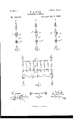
Figure 1 shows an end view of a bed-frame provided with an upwardly and outwardly curved end rail and stay therefor embodying this invention; Fig. 2, a vertical section of the parts shown in Fig; 1, taken on the dotted line w a; Fig. 3, an end ,view of a bed-frame having an upwardly and outwardly curved end rail and a modified form of stay therefor; Fig. 4, a vertical section of the parts shown in Fig. 3, taken on the dotted line y y; Fig. 5, a perspective detail showing the end rail and stay therefor and casting or support to which the end rail is connected; Fig. 6, avertical section of a bed-frame having a straight end rail and stay therefor; Fig. 7, a vertical 'sec tion of a bed-frame having an upwardlycurved end rail and stay therefor; Fig. 8, a vertical section of a bed-frame having an outwardly-curved end rail and a stay therefor; Fig. 9, a modification to be referred to, and Fig. 10 a detail showing a narrow bed with vertical stay omitted and end rail connected to the corner-blocks at points remote from their ends.
The bed -frame is herein represented as comprising corner-posts a, castings or blocks 1) thereon, provided with dovetailed recesses c to receive the correspondingly-shaped proj ections, (not here shown, but which are ordinarily provided at the ends of the side rail 01,) and end rail connected with or attached to the blocks Z).
One of the ends, as e,is curved upwardly and outwardly, as shown in Figs. 1 to 5, and is provided with studs or other suitable means to furnish a point of attachment for a bedbottom, and to prevent the said end rail from projecting too far outwardly as to be objectionable it is attached to the block b at a remote point from its connection with the corner-post, as at 20, for instance.
' As represented at Fig. 1, a stay or post f passes through a hole in an ear f on the upwardly and outwardly curved end rail 8, said post being connected rigidly to the crossbars f f The bed-bottom is attached to the end and side rails in any usual or suitable manner,
and as the end rail e is curved upwardly thesurface of the bed-bottom in its normal position is slightly curved or arched, and as said end rail is also curved outwardly the longitudinal strain on the bed-bottom at the cen ter is greater than at the edges. Such curvatures being given to the end rail thus effectually prevents sagging of the bed-bottom.
Instead of employing a post, as f, which passes through an car on the end rail as a stay to hold it in fixed position against rocking or tilting, which would be the case were said stay omitted, I may employ any other suitable form or construction of stay-such, for instance, as the vertical rod 3, (see Figs. 3 and 4,) connected at the ends to the crossbars f f and at a point between its ends to the end rail by a bolt 2-orI may employ the post f, (see Fig. 9,) which is connected to the end rail at one end and to the cross-bars f f thereby obtaining two fixed points of connection for the post. A vertical stay of this kind is also of advantage for other forms of end rail, particularly in wide beds-such, for instance, as shown in Fig. 6, where a straight end rail is shown, and in Fig. 7, where an upwardly-curved end rail is shown, or in Fig. 8, where an outwardly-curved end rail is shown.
By providing corner-blocks b, as herein shown, having a post-receiving hole and an elongated recess to receive the projection on the end of side rail in line with each other, a long block is necessitated, and by connecting the outwardly-curved end rail to said block at a point beside or opposite the recess a, as
' at 20, instead of opposite the post-receiving hole the said end rail will not project beyond other parts of the head or foot of the bed, as the case may be.
For narrow beds it is possible to omit the vertical stay, but in the event of the end rail being curved outwardly, whether also curved upwardly or not, I connect it to the cornerblocks at the points 20, as above mentioned, and in case said end rail is connected to the corner-blocks at points sufficiently remote from the posts the coverlet of the bed may hang outside of and cover said end rail and yet be inside of the head or foot of the bed, or both, as the case may be. A narrow bed embodying this feature of the invention is represented in Fig. 10.
While I have herein represented the end rail as connected at its ends to the cornerblocks, nevertheless, so far as its connection with the vertical stay is concerned, it may be otherwise supported at the ends.
I claim- 1.. A bed-bottom comprising corner-posts having blocks thereon, side rails, an end rail curved continuously upwardly and outwardly, having the inner ends thereof connected at or near the inner ends of the cornerblocks so as to lie within the plane in which the corner-posts'are located, a post passing through the end rail, and a fixed support for said post, substantially as described.
2. A bed-bottom comprising corner-posts, side rails, an end rail curved outwardly, having the inner ends thereof connected at or near the inner ends of the corner-blocks, and cross-bars connected to the corner-posts above and below the end rail, and supports for the end rail connected to the end rail and cross-bars, substantially as described.
3. A bed-bottom, and an end curved continuously upwardly and outwardly to which said bed-bottom is connected, combined with corner-posts, and blocks thereon to which said end rail curved as described, is connected, cross-bars above and below said end rail connected to the corner-posts, and supports forthe curved end rail connected to said end rail and said cross-bars, substantially as described.
4. A bed-bottom comprising corner-posts having blocks thereon, side rails, an end rail curved outwardly, having the inner ends thereof connected at or near the inner ends of the corner-blocks so as to lie within the plane in which the corner-posts are located, cross-bars connected to the corner-posts above and below the end rail, and supports for the end rail connected to the end rail and the cross-bars, substantially as described.
In testimony whereof I have signed my name to this specification in the presence of two subscribing witnesses.
FRANCIS G. GALE.
\Vitnesses:
W. H. WARD, CARL SUANSON.
Publications (1)
| Publication Number | Publication Date |
|---|---|
| US598564A true US598564A (en) | 1898-02-08 |
Family
ID=2667206
Family Applications (1)
| Application Number | Title | Priority Date | Filing Date |
|---|---|---|---|
| US598564D Expired - Lifetime US598564A (en) | Metallic bedstead |
Country Status (1)
| Country | Link |
|---|---|
| US (1) | US598564A (en) |
-
0
- US US598564D patent/US598564A/en not_active Expired - Lifetime
Similar Documents
| Publication | Publication Date | Title |
|---|---|---|
| US598564A (en) | Metallic bedstead | |
| US160809A (en) | Improvement in spring bed-bottoms | |
| US819671A (en) | Bed-spring. | |
| US195550A (en) | Improvement in bed-bottoms | |
| US892566A (en) | Spring-mattress. | |
| US555042A (en) | Combined bedstead-fastening and bed-spring support | |
| US574742A (en) | Spring-bed frame | |
| US651723A (en) | Bedstead. | |
| US1126869A (en) | Spring-bed. | |
| US801462A (en) | Mattress-frame. | |
| US534621A (en) | The nqbnis peters co | |
| US585666A (en) | Francis g | |
| US767151A (en) | Bed or couch. | |
| US261148A (en) | Thomas p | |
| US676652A (en) | Hook or support for bed-spring frames. | |
| US602656A (en) | Adolf g | |
| US725030A (en) | Spring-support for bed-bottoms. | |
| US615038A (en) | Bed-bottom frame | |
| US950625A (en) | Metal bedstead. | |
| US524955A (en) | James b | |
| US361496A (en) | Bedstead | |
| US625112A (en) | Metallic bed | |
| US1003188A (en) | Bed construction. | |
| US477430A (en) | James massie | |
| US209124A (en) | Improvement in bed-bottoms |