US5982056A - Thermosetting resin composition, electrically insulated coil, electric rotating machine and method for producing same - Google Patents
Thermosetting resin composition, electrically insulated coil, electric rotating machine and method for producing same Download PDFInfo
- Publication number
- US5982056A US5982056A US08/866,147 US86614797A US5982056A US 5982056 A US5982056 A US 5982056A US 86614797 A US86614797 A US 86614797A US 5982056 A US5982056 A US 5982056A
- Authority
- US
- United States
- Prior art keywords
- epoxy resin
- epoxy resins
- anthracene
- represented
- iron core
- Prior art date
- Legal status (The legal status is an assumption and is not a legal conclusion. Google has not performed a legal analysis and makes no representation as to the accuracy of the status listed.)
- Expired - Fee Related
Links
- 239000011342 resin composition Substances 0.000 title claims abstract description 99
- 229920001187 thermosetting polymer Polymers 0.000 title claims abstract description 97
- 238000004519 manufacturing process Methods 0.000 title claims description 15
- 239000003822 epoxy resin Substances 0.000 claims abstract description 250
- 229920000647 polyepoxide Polymers 0.000 claims abstract description 250
- LNEPOXFFQSENCJ-UHFFFAOYSA-N haloperidol Chemical compound C1CC(O)(C=2C=CC(Cl)=CC=2)CCN1CCCC(=O)C1=CC=C(F)C=C1 LNEPOXFFQSENCJ-UHFFFAOYSA-N 0.000 claims abstract description 122
- 239000000126 substance Substances 0.000 claims abstract description 71
- RTZKZFJDLAIYFH-UHFFFAOYSA-N Diethyl ether Chemical compound CCOCC RTZKZFJDLAIYFH-UHFFFAOYSA-N 0.000 claims abstract description 64
- 239000003054 catalyst Substances 0.000 claims abstract description 55
- -1 p-(2,3-epoxypropoxy) phenyl groups Chemical group 0.000 claims abstract description 46
- 239000003795 chemical substances by application Substances 0.000 claims abstract description 38
- 150000008065 acid anhydrides Chemical class 0.000 claims abstract description 32
- GYZLOYUZLJXAJU-UHFFFAOYSA-N diglycidyl ether Chemical compound C1OC1COCC1CO1 GYZLOYUZLJXAJU-UHFFFAOYSA-N 0.000 claims abstract description 32
- 125000005577 anthracene group Chemical group 0.000 claims abstract description 30
- 229910052751 metal Inorganic materials 0.000 claims abstract description 30
- 239000002184 metal Substances 0.000 claims abstract description 30
- 230000001588 bifunctional effect Effects 0.000 claims abstract description 28
- 125000001624 naphthyl group Chemical group 0.000 claims abstract description 28
- BWLBGMIXKSTLSX-UHFFFAOYSA-N 2-hydroxyisobutyric acid Chemical compound CC(C)(O)C(O)=O BWLBGMIXKSTLSX-UHFFFAOYSA-N 0.000 claims abstract description 24
- UTCOUOISVRSLSH-UHFFFAOYSA-N 1,2-Anthracenediol Chemical compound C1=CC=CC2=CC3=C(O)C(O)=CC=C3C=C21 UTCOUOISVRSLSH-UHFFFAOYSA-N 0.000 claims abstract description 22
- SLOLMTWBBAFOKJ-UHFFFAOYSA-N anthracene-1,2,3-triol Chemical compound C1=CC=C2C=C(C(O)=C(C(O)=C3)O)C3=CC2=C1 SLOLMTWBBAFOKJ-UHFFFAOYSA-N 0.000 claims abstract description 22
- XEEYBQQBJWHFJM-UHFFFAOYSA-N Iron Chemical group [Fe] XEEYBQQBJWHFJM-UHFFFAOYSA-N 0.000 claims description 80
- 239000000463 material Substances 0.000 claims description 75
- UFWIBTONFRDIAS-UHFFFAOYSA-N Naphthalene Chemical group C1=CC=CC2=CC=CC=C21 UFWIBTONFRDIAS-UHFFFAOYSA-N 0.000 claims description 34
- 239000004020 conductor Substances 0.000 claims description 26
- 238000000034 method Methods 0.000 claims description 26
- 238000004804 winding Methods 0.000 claims description 18
- 125000001997 phenyl group Chemical group [H]C1=C([H])C([H])=C(*)C([H])=C1[H] 0.000 claims description 12
- 125000000217 alkyl group Chemical group 0.000 claims description 10
- 125000004432 carbon atom Chemical group C* 0.000 claims description 10
- 229910052726 zirconium Inorganic materials 0.000 claims description 10
- 125000002496 methyl group Chemical group [H]C([H])([H])* 0.000 claims description 9
- 229920001721 polyimide Polymers 0.000 claims description 9
- 229910052725 zinc Inorganic materials 0.000 claims description 9
- 229910052748 manganese Inorganic materials 0.000 claims description 8
- XSTXAVWGXDQKEL-UHFFFAOYSA-N Trichloroethylene Chemical compound ClC=C(Cl)Cl XSTXAVWGXDQKEL-UHFFFAOYSA-N 0.000 claims 2
- 101100177155 Arabidopsis thaliana HAC1 gene Proteins 0.000 claims 1
- 101100434170 Oryza sativa subsp. japonica ACR2.1 gene Proteins 0.000 claims 1
- 101100434171 Oryza sativa subsp. japonica ACR2.2 gene Proteins 0.000 claims 1
- LCFVJGUPQDGYKZ-UHFFFAOYSA-N Bisphenol A diglycidyl ether Chemical compound C=1C=C(OCC2OC2)C=CC=1C(C)(C)C(C=C1)=CC=C1OCC1CO1 LCFVJGUPQDGYKZ-UHFFFAOYSA-N 0.000 description 75
- MMIPFLVOWGHZQD-UHFFFAOYSA-N manganese(3+) Chemical compound [Mn+3] MMIPFLVOWGHZQD-UHFFFAOYSA-N 0.000 description 56
- 239000004593 Epoxy Substances 0.000 description 36
- 239000011230 binding agent Substances 0.000 description 31
- 239000010445 mica Substances 0.000 description 29
- 229910052618 mica group Inorganic materials 0.000 description 29
- 229920005989 resin Polymers 0.000 description 28
- 239000011347 resin Substances 0.000 description 28
- 238000005470 impregnation Methods 0.000 description 25
- 239000000203 mixture Substances 0.000 description 25
- 238000010438 heat treatment Methods 0.000 description 18
- ZWEHNKRNPOVVGH-UHFFFAOYSA-N 2-Butanone Chemical compound CCC(C)=O ZWEHNKRNPOVVGH-UHFFFAOYSA-N 0.000 description 15
- 230000008569 process Effects 0.000 description 14
- 239000000243 solution Substances 0.000 description 13
- 239000010410 layer Substances 0.000 description 12
- PNEYBMLMFCGWSK-UHFFFAOYSA-N aluminium oxide Inorganic materials [O-2].[O-2].[O-2].[Al+3].[Al+3] PNEYBMLMFCGWSK-UHFFFAOYSA-N 0.000 description 11
- 230000000052 comparative effect Effects 0.000 description 11
- POILWHVDKZOXJZ-ARJAWSKDSA-M (z)-4-oxopent-2-en-2-olate Chemical compound C\C([O-])=C\C(C)=O POILWHVDKZOXJZ-ARJAWSKDSA-M 0.000 description 10
- 239000002131 composite material Substances 0.000 description 9
- 150000001875 compounds Chemical class 0.000 description 9
- 239000004094 surface-active agent Substances 0.000 description 8
- 238000012360 testing method Methods 0.000 description 8
- VYPSYNLAJGMNEJ-UHFFFAOYSA-N Silicium dioxide Chemical compound O=[Si]=O VYPSYNLAJGMNEJ-UHFFFAOYSA-N 0.000 description 7
- RTAQQCXQSZGOHL-UHFFFAOYSA-N Titanium Chemical compound [Ti] RTAQQCXQSZGOHL-UHFFFAOYSA-N 0.000 description 7
- IISBACLAFKSPIT-UHFFFAOYSA-N bisphenol A Chemical compound C=1C=C(O)C=CC=1C(C)(C)C1=CC=C(O)C=C1 IISBACLAFKSPIT-UHFFFAOYSA-N 0.000 description 7
- 239000002904 solvent Substances 0.000 description 7
- 229920003235 aromatic polyamide Polymers 0.000 description 6
- PXKLMJQFEQBVLD-UHFFFAOYSA-N bisphenol F Chemical compound C1=CC(O)=CC=C1CC1=CC=C(O)C=C1 PXKLMJQFEQBVLD-UHFFFAOYSA-N 0.000 description 6
- 238000006243 chemical reaction Methods 0.000 description 6
- 239000006185 dispersion Substances 0.000 description 6
- 238000002156 mixing Methods 0.000 description 6
- NXPPAOGUKPJVDI-UHFFFAOYSA-N naphthalene-1,2-diol Chemical class C1=CC=CC2=C(O)C(O)=CC=C21 NXPPAOGUKPJVDI-UHFFFAOYSA-N 0.000 description 6
- 238000002360 preparation method Methods 0.000 description 6
- 238000013019 agitation Methods 0.000 description 5
- 239000004760 aramid Substances 0.000 description 5
- 239000007795 chemical reaction product Substances 0.000 description 5
- XLJKHNWPARRRJB-UHFFFAOYSA-N cobalt(2+) Chemical compound [Co+2] XLJKHNWPARRRJB-UHFFFAOYSA-N 0.000 description 5
- 238000005520 cutting process Methods 0.000 description 5
- PYNVYLAZKQQFLK-UHFFFAOYSA-N naphthalene-1,2,3,4-tetrol Chemical class C1=CC=CC2=C(O)C(O)=C(O)C(O)=C21 PYNVYLAZKQQFLK-UHFFFAOYSA-N 0.000 description 5
- NCIAGQNZQHYKGR-UHFFFAOYSA-N naphthalene-1,2,3-triol Chemical class C1=CC=C2C(O)=C(O)C(O)=CC2=C1 NCIAGQNZQHYKGR-UHFFFAOYSA-N 0.000 description 5
- 229920003986 novolac Polymers 0.000 description 5
- 239000000843 powder Substances 0.000 description 5
- 239000000047 product Substances 0.000 description 5
- LTVUCOSIZFEASK-MPXCPUAZSA-N (3ar,4s,7r,7as)-3a-methyl-3a,4,7,7a-tetrahydro-4,7-methano-2-benzofuran-1,3-dione Chemical compound C([C@H]1C=C2)[C@H]2[C@H]2[C@]1(C)C(=O)OC2=O LTVUCOSIZFEASK-MPXCPUAZSA-N 0.000 description 4
- ADVORQMAWLEPOI-XHTSQIMGSA-N (e)-4-hydroxypent-3-en-2-one;oxotitanium Chemical compound [Ti]=O.C\C(O)=C/C(C)=O.C\C(O)=C/C(C)=O ADVORQMAWLEPOI-XHTSQIMGSA-N 0.000 description 4
- RDMHXWZYVFGYSF-LNTINUHCSA-N (z)-4-hydroxypent-3-en-2-one;manganese Chemical compound [Mn].C\C(O)=C\C(C)=O.C\C(O)=C\C(C)=O.C\C(O)=C\C(C)=O RDMHXWZYVFGYSF-LNTINUHCSA-N 0.000 description 4
- IKHGUXGNUITLKF-UHFFFAOYSA-N Acetaldehyde Chemical compound CC=O IKHGUXGNUITLKF-UHFFFAOYSA-N 0.000 description 4
- 239000004642 Polyimide Substances 0.000 description 4
- 239000007983 Tris buffer Substances 0.000 description 4
- 239000002253 acid Substances 0.000 description 4
- FCEOGYWNOSBEPV-FDGPNNRMSA-N cobalt;(z)-4-hydroxypent-3-en-2-one Chemical compound [Co].C\C(O)=C\C(C)=O.C\C(O)=C\C(C)=O FCEOGYWNOSBEPV-FDGPNNRMSA-N 0.000 description 4
- JUPWRUDTZGBNEX-UHFFFAOYSA-N cobalt;pentane-2,4-dione Chemical compound [Co].CC(=O)CC(C)=O.CC(=O)CC(C)=O.CC(=O)CC(C)=O JUPWRUDTZGBNEX-UHFFFAOYSA-N 0.000 description 4
- USIUVYZYUHIAEV-UHFFFAOYSA-N diphenyl ether Chemical compound C=1C=CC=CC=1OC1=CC=CC=C1 USIUVYZYUHIAEV-UHFFFAOYSA-N 0.000 description 4
- 238000004090 dissolution Methods 0.000 description 4
- 239000004744 fabric Substances 0.000 description 4
- 239000011521 glass Substances 0.000 description 4
- 239000003365 glass fiber Substances 0.000 description 4
- 238000009413 insulation Methods 0.000 description 4
- VNWKTOKETHGBQD-UHFFFAOYSA-N methane Chemical compound C VNWKTOKETHGBQD-UHFFFAOYSA-N 0.000 description 4
- 230000009467 reduction Effects 0.000 description 4
- 239000012779 reinforcing material Substances 0.000 description 4
- BCMKHWMDTMUUSI-UHFFFAOYSA-N tetrahydroxynaphthalene Natural products OC1=CC(O)=CC2=CC(O)=CC(O)=C21 BCMKHWMDTMUUSI-UHFFFAOYSA-N 0.000 description 4
- YOBOXHGSEJBUPB-MTOQALJVSA-N (z)-4-hydroxypent-3-en-2-one;zirconium Chemical compound [Zr].C\C(O)=C\C(C)=O.C\C(O)=C\C(C)=O.C\C(O)=C\C(C)=O.C\C(O)=C\C(C)=O YOBOXHGSEJBUPB-MTOQALJVSA-N 0.000 description 3
- JFNFZPRUTDFBGN-UHFFFAOYSA-N 2-[[4-[4,4-bis[4-(oxiran-2-ylmethoxy)phenyl]butan-2-yl]phenoxy]methyl]oxirane Chemical compound C=1C=C(OCC2OC2)C=CC=1C(C)CC(C=1C=CC(OCC2OC2)=CC=1)C(C=C1)=CC=C1OCC1CO1 JFNFZPRUTDFBGN-UHFFFAOYSA-N 0.000 description 3
- QTWJRLJHJPIABL-UHFFFAOYSA-N 2-methylphenol;3-methylphenol;4-methylphenol Chemical compound CC1=CC=C(O)C=C1.CC1=CC=CC(O)=C1.CC1=CC=CC=C1O QTWJRLJHJPIABL-UHFFFAOYSA-N 0.000 description 3
- MFWFDRBPQDXFRC-UHFFFAOYSA-N 4-hydroxypent-3-en-2-one;vanadium Chemical compound [V].CC(O)=CC(C)=O.CC(O)=CC(C)=O.CC(O)=CC(C)=O MFWFDRBPQDXFRC-UHFFFAOYSA-N 0.000 description 3
- MWSKJDNQKGCKPA-UHFFFAOYSA-N 6-methyl-3a,4,5,7a-tetrahydro-2-benzofuran-1,3-dione Chemical compound C1CC(C)=CC2C(=O)OC(=O)C12 MWSKJDNQKGCKPA-UHFFFAOYSA-N 0.000 description 3
- 229930185605 Bisphenol Natural products 0.000 description 3
- WSFSSNUMVMOOMR-UHFFFAOYSA-N Formaldehyde Chemical compound O=C WSFSSNUMVMOOMR-UHFFFAOYSA-N 0.000 description 3
- ISWSIDIOOBJBQZ-UHFFFAOYSA-N Phenol Chemical compound OC1=CC=CC=C1 ISWSIDIOOBJBQZ-UHFFFAOYSA-N 0.000 description 3
- 239000002202 Polyethylene glycol Substances 0.000 description 3
- 150000001346 alkyl aryl ethers Chemical class 0.000 description 3
- SVAAPDAHDVBOMW-ORWWTJHYSA-N cobalt (E)-3-hydroxy-1-phenylbut-2-en-1-one Chemical compound [Co].C\C(O)=C/C(=O)c1ccccc1.C\C(O)=C/C(=O)c1ccccc1 SVAAPDAHDVBOMW-ORWWTJHYSA-N 0.000 description 3
- 229930003836 cresol Natural products 0.000 description 3
- 230000007423 decrease Effects 0.000 description 3
- 239000003085 diluting agent Substances 0.000 description 3
- RAXXELZNTBOGNW-UHFFFAOYSA-N imidazole Natural products C1=CNC=N1 RAXXELZNTBOGNW-UHFFFAOYSA-N 0.000 description 3
- 238000003780 insertion Methods 0.000 description 3
- 230000037431 insertion Effects 0.000 description 3
- 125000001449 isopropyl group Chemical group [H]C([H])([H])C([H])(*)C([H])([H])[H] 0.000 description 3
- VYKXQOYUCMREIS-UHFFFAOYSA-N methylhexahydrophthalic anhydride Chemical compound C1CCCC2C(=O)OC(=O)C21C VYKXQOYUCMREIS-UHFFFAOYSA-N 0.000 description 3
- 229920001223 polyethylene glycol Polymers 0.000 description 3
- 239000000377 silicon dioxide Substances 0.000 description 3
- 239000002966 varnish Substances 0.000 description 3
- XLYOFNOQVPJJNP-UHFFFAOYSA-N water Substances O XLYOFNOQVPJJNP-UHFFFAOYSA-N 0.000 description 3
- WYTZZXDRDKSJID-UHFFFAOYSA-N (3-aminopropyl)triethoxysilane Chemical compound CCO[Si](OCC)(OCC)CCCN WYTZZXDRDKSJID-UHFFFAOYSA-N 0.000 description 2
- KNDQHSIWLOJIGP-UMRXKNAASA-N (3ar,4s,7r,7as)-rel-3a,4,7,7a-tetrahydro-4,7-methanoisobenzofuran-1,3-dione Chemical compound O=C1OC(=O)[C@@H]2[C@H]1[C@]1([H])C=C[C@@]2([H])C1 KNDQHSIWLOJIGP-UMRXKNAASA-N 0.000 description 2
- DNIAPMSPPWPWGF-GSVOUGTGSA-N (R)-(-)-Propylene glycol Chemical compound C[C@@H](O)CO DNIAPMSPPWPWGF-GSVOUGTGSA-N 0.000 description 2
- NHEVNUARLCWEED-UHFFFAOYSA-N 1,4,5-Naphthalenetriol Chemical compound C1=CC=C2C(O)=CC=C(O)C2=C1O NHEVNUARLCWEED-UHFFFAOYSA-N 0.000 description 2
- HDDQXUDCEIMISH-UHFFFAOYSA-N 2-[[4-[1,2,2-tris[4-(oxiran-2-ylmethoxy)phenyl]ethyl]phenoxy]methyl]oxirane Chemical compound C1OC1COC(C=C1)=CC=C1C(C=1C=CC(OCC2OC2)=CC=1)C(C=1C=CC(OCC2OC2)=CC=1)C(C=C1)=CC=C1OCC1CO1 HDDQXUDCEIMISH-UHFFFAOYSA-N 0.000 description 2
- FMQZMCFUGDLKQM-UHFFFAOYSA-N 2-[[4-[1,3,3-tris[4-(oxiran-2-ylmethoxy)phenyl]propyl]phenoxy]methyl]oxirane Chemical compound C1OC1COC(C=C1)=CC=C1C(C=1C=CC(OCC2OC2)=CC=1)CC(C=1C=CC(OCC2OC2)=CC=1)C(C=C1)=CC=C1OCC1CO1 FMQZMCFUGDLKQM-UHFFFAOYSA-N 0.000 description 2
- WZKPOAWBXHEIKH-UHFFFAOYSA-N 2-[[4-[1,3-bis[4-(oxiran-2-ylmethoxy)phenyl]propyl]phenoxy]methyl]oxirane Chemical compound C=1C=C(OCC2OC2)C=CC=1C(C=1C=CC(OCC2OC2)=CC=1)CCC(C=C1)=CC=C1OCC1CO1 WZKPOAWBXHEIKH-UHFFFAOYSA-N 0.000 description 2
- IGZBSJAMZHNHKE-UHFFFAOYSA-N 2-[[4-[bis[4-(oxiran-2-ylmethoxy)phenyl]methyl]phenoxy]methyl]oxirane Chemical compound C1OC1COC(C=C1)=CC=C1C(C=1C=CC(OCC2OC2)=CC=1)C(C=C1)=CC=C1OCC1CO1 IGZBSJAMZHNHKE-UHFFFAOYSA-N 0.000 description 2
- MEVBAGCIOOTPLF-UHFFFAOYSA-N 2-[[5-(oxiran-2-ylmethoxy)naphthalen-2-yl]oxymethyl]oxirane Chemical compound C1OC1COC(C=C1C=CC=2)=CC=C1C=2OCC1CO1 MEVBAGCIOOTPLF-UHFFFAOYSA-N 0.000 description 2
- CDAWCLOXVUBKRW-UHFFFAOYSA-N 2-aminophenol Chemical compound NC1=CC=CC=C1O CDAWCLOXVUBKRW-UHFFFAOYSA-N 0.000 description 2
- JWAZRIHNYRIHIV-UHFFFAOYSA-N 2-naphthol Chemical compound C1=CC=CC2=CC(O)=CC=C21 JWAZRIHNYRIHIV-UHFFFAOYSA-N 0.000 description 2
- UUEWCQRISZBELL-UHFFFAOYSA-N 3-trimethoxysilylpropane-1-thiol Chemical compound CO[Si](OC)(OC)CCCS UUEWCQRISZBELL-UHFFFAOYSA-N 0.000 description 2
- VTYYLEPIZMXCLO-UHFFFAOYSA-L Calcium carbonate Chemical compound [Ca+2].[O-]C([O-])=O VTYYLEPIZMXCLO-UHFFFAOYSA-L 0.000 description 2
- 241001251094 Formica Species 0.000 description 2
- OAKJQQAXSVQMHS-UHFFFAOYSA-N Hydrazine Chemical compound NN OAKJQQAXSVQMHS-UHFFFAOYSA-N 0.000 description 2
- 239000004696 Poly ether ether ketone Substances 0.000 description 2
- UMHKOAYRTRADAT-UHFFFAOYSA-N [hydroxy(octoxy)phosphoryl] octyl hydrogen phosphate Chemical compound CCCCCCCCOP(O)(=O)OP(O)(=O)OCCCCCCCC UMHKOAYRTRADAT-UHFFFAOYSA-N 0.000 description 2
- 239000000853 adhesive Substances 0.000 description 2
- 230000001070 adhesive effect Effects 0.000 description 2
- REDXJYDRNCIFBQ-UHFFFAOYSA-N aluminium(3+) Chemical compound [Al+3] REDXJYDRNCIFBQ-UHFFFAOYSA-N 0.000 description 2
- MQPPCKJJFDNPHJ-UHFFFAOYSA-K aluminum;3-oxohexanoate Chemical compound [Al+3].CCCC(=O)CC([O-])=O.CCCC(=O)CC([O-])=O.CCCC(=O)CC([O-])=O MQPPCKJJFDNPHJ-UHFFFAOYSA-K 0.000 description 2
- 238000005452 bending Methods 0.000 description 2
- MJSNUBOCVAKFIJ-LNTINUHCSA-N chromium;(z)-4-oxoniumylidenepent-2-en-2-olate Chemical compound [Cr].C\C(O)=C\C(C)=O.C\C(O)=C\C(C)=O.C\C(O)=C\C(C)=O MJSNUBOCVAKFIJ-LNTINUHCSA-N 0.000 description 2
- 238000000576 coating method Methods 0.000 description 2
- 230000000694 effects Effects 0.000 description 2
- XYIBRDXRRQCHLP-UHFFFAOYSA-N ethyl acetoacetate Chemical compound CCOC(=O)CC(C)=O XYIBRDXRRQCHLP-UHFFFAOYSA-N 0.000 description 2
- 239000000945 filler Substances 0.000 description 2
- 239000011256 inorganic filler Substances 0.000 description 2
- 229910003475 inorganic filler Inorganic materials 0.000 description 2
- YCAFCYKVEIHDQJ-UHFFFAOYSA-N naphthalene-1,4,6-triol Chemical compound OC1=CC=C(O)C2=CC(O)=CC=C21 YCAFCYKVEIHDQJ-UHFFFAOYSA-N 0.000 description 2
- FZZQNEVOYIYFPF-UHFFFAOYSA-N naphthalene-1,6-diol Chemical compound OC1=CC=CC2=CC(O)=CC=C21 FZZQNEVOYIYFPF-UHFFFAOYSA-N 0.000 description 2
- OENHRRVNRZBNNS-UHFFFAOYSA-N naphthalene-1,8-diol Chemical compound C1=CC(O)=C2C(O)=CC=CC2=C1 OENHRRVNRZBNNS-UHFFFAOYSA-N 0.000 description 2
- BMGNSKKZFQMGDH-FDGPNNRMSA-L nickel(2+);(z)-4-oxopent-2-en-2-olate Chemical compound [Ni+2].C\C([O-])=C\C(C)=O.C\C([O-])=C\C(C)=O BMGNSKKZFQMGDH-FDGPNNRMSA-L 0.000 description 2
- LQERIDTXQFOHKA-UHFFFAOYSA-N nonadecane Chemical compound CCCCCCCCCCCCCCCCCCC LQERIDTXQFOHKA-UHFFFAOYSA-N 0.000 description 2
- 229920002530 polyetherether ketone Polymers 0.000 description 2
- 229920001021 polysulfide Polymers 0.000 description 2
- 239000005077 polysulfide Substances 0.000 description 2
- 150000008117 polysulfides Polymers 0.000 description 2
- ZFRGVVDFMHJCDV-UHFFFAOYSA-N tri(propan-2-yloxy)alumane Chemical compound [Al+3].CC([O-])C.[Al+3].CC([O-])C.CC([O-])C.CC([O-])C.CC([O-])C.CC([O-])C ZFRGVVDFMHJCDV-UHFFFAOYSA-N 0.000 description 2
- BPSIOYPQMFLKFR-UHFFFAOYSA-N trimethoxy-[3-(oxiran-2-ylmethoxy)propyl]silane Chemical compound CO[Si](OC)(OC)CCCOCC1CO1 BPSIOYPQMFLKFR-UHFFFAOYSA-N 0.000 description 2
- PUPZLCDOIYMWBV-UHFFFAOYSA-N (+/-)-1,3-Butanediol Chemical compound CC(O)CCO PUPZLCDOIYMWBV-UHFFFAOYSA-N 0.000 description 1
- MUTGBJKUEZFXGO-OLQVQODUSA-N (3as,7ar)-3a,4,5,6,7,7a-hexahydro-2-benzofuran-1,3-dione Chemical compound C1CCC[C@@H]2C(=O)OC(=O)[C@@H]21 MUTGBJKUEZFXGO-OLQVQODUSA-N 0.000 description 1
- KMOUUZVZFBCRAM-OLQVQODUSA-N (3as,7ar)-3a,4,7,7a-tetrahydro-2-benzofuran-1,3-dione Chemical compound C1C=CC[C@@H]2C(=O)OC(=O)[C@@H]21 KMOUUZVZFBCRAM-OLQVQODUSA-N 0.000 description 1
- KILURZWTCGSYRE-LNTINUHCSA-K (z)-4-bis[[(z)-4-oxopent-2-en-2-yl]oxy]alumanyloxypent-3-en-2-one Chemical compound CC(=O)\C=C(\C)O[Al](O\C(C)=C/C(C)=O)O\C(C)=C/C(C)=O KILURZWTCGSYRE-LNTINUHCSA-K 0.000 description 1
- FRASJONUBLZVQX-UHFFFAOYSA-N 1,4-dioxonaphthalene Natural products C1=CC=C2C(=O)C=CC(=O)C2=C1 FRASJONUBLZVQX-UHFFFAOYSA-N 0.000 description 1
- BOKGTLAJQHTOKE-UHFFFAOYSA-N 1,5-dihydroxynaphthalene Chemical compound C1=CC=C2C(O)=CC=CC2=C1O BOKGTLAJQHTOKE-UHFFFAOYSA-N 0.000 description 1
- KWKAKUADMBZCLK-UHFFFAOYSA-N 1-octene Chemical group CCCCCCC=C KWKAKUADMBZCLK-UHFFFAOYSA-N 0.000 description 1
- STMDPCBYJCIZOD-UHFFFAOYSA-N 2-(2,4-dinitroanilino)-4-methylpentanoic acid Chemical compound CC(C)CC(C(O)=O)NC1=CC=C([N+]([O-])=O)C=C1[N+]([O-])=O STMDPCBYJCIZOD-UHFFFAOYSA-N 0.000 description 1
- YSUQLAYJZDEMOT-UHFFFAOYSA-N 2-(butoxymethyl)oxirane Chemical compound CCCCOCC1CO1 YSUQLAYJZDEMOT-UHFFFAOYSA-N 0.000 description 1
- FALRKNHUBBKYCC-UHFFFAOYSA-N 2-(chloromethyl)pyridine-3-carbonitrile Chemical compound ClCC1=NC=CC=C1C#N FALRKNHUBBKYCC-UHFFFAOYSA-N 0.000 description 1
- OGRULRAOMCDCBO-UHFFFAOYSA-N 2-[[1-(oxiran-2-ylmethoxy)naphthalen-2-yl]oxymethyl]oxirane Chemical compound C1OC1COC1=CC=C2C=CC=CC2=C1OCC1CO1 OGRULRAOMCDCBO-UHFFFAOYSA-N 0.000 description 1
- OLZORQZMRXBLTQ-UHFFFAOYSA-N 2-[[1-[1-[2,7-bis(oxiran-2-ylmethoxy)naphthalen-1-yl]ethyl]-7-(oxiran-2-ylmethoxy)naphthalen-2-yl]oxymethyl]oxirane Chemical compound C1OC1COC=1C=CC2=CC=C(OCC3OC3)C=C2C=1C(C)C(C1=CC(OCC2OC2)=CC=C1C=C1)=C1OCC1CO1 OLZORQZMRXBLTQ-UHFFFAOYSA-N 0.000 description 1
- XOSCKTQMAZSFBZ-UHFFFAOYSA-N 2-[[1-[[2,7-bis(oxiran-2-ylmethoxy)naphthalen-1-yl]methyl]-7-(oxiran-2-ylmethoxy)naphthalen-2-yl]oxymethyl]oxirane Chemical compound C1OC1COC(C=C1C=2CC=3C4=CC(OCC5OC5)=CC=C4C=CC=3OCC3OC3)=CC=C1C=CC=2OCC1CO1 XOSCKTQMAZSFBZ-UHFFFAOYSA-N 0.000 description 1
- HEBZREJQBKNHBH-UHFFFAOYSA-N 2-[[1-[[2,7-bis(oxiran-2-ylmethoxy)naphthalen-1-yl]methyl]naphthalen-2-yl]oxymethyl]oxirane Chemical compound C1OC1COC(C=C1C=2CC=3C4=CC=CC=C4C=CC=3OCC3OC3)=CC=C1C=CC=2OCC1CO1 HEBZREJQBKNHBH-UHFFFAOYSA-N 0.000 description 1
- JLBBZRWVDMCDLV-UHFFFAOYSA-N 2-[[3-(oxiran-2-ylmethoxy)naphthalen-1-yl]oxymethyl]oxirane Chemical compound C1OC1COC(C=C1C=CC=CC1=1)=CC=1OCC1CO1 JLBBZRWVDMCDLV-UHFFFAOYSA-N 0.000 description 1
- MPYZUNNAXVBHDC-UHFFFAOYSA-N 2-[[3-(oxiran-2-ylmethoxy)naphthalen-2-yl]oxymethyl]oxirane Chemical compound C1OC1COC1=CC2=CC=CC=C2C=C1OCC1CO1 MPYZUNNAXVBHDC-UHFFFAOYSA-N 0.000 description 1
- RHYLFJIYMVTKQO-UHFFFAOYSA-N 2-[[4-(oxiran-2-ylmethoxy)naphthalen-1-yl]oxymethyl]oxirane Chemical compound C1OC1COC(C1=CC=CC=C11)=CC=C1OCC1CO1 RHYLFJIYMVTKQO-UHFFFAOYSA-N 0.000 description 1
- PBDZZGWMPMHHJF-UHFFFAOYSA-N 2-[[4-[1,1-bis[4-(oxiran-2-ylmethoxy)phenyl]propan-2-yl]phenoxy]methyl]oxirane Chemical compound C=1C=C(OCC2OC2)C=CC=1C(C)C(C=1C=CC(OCC2OC2)=CC=1)C(C=C1)=CC=C1OCC1CO1 PBDZZGWMPMHHJF-UHFFFAOYSA-N 0.000 description 1
- KSPFYJOGDWSWIY-UHFFFAOYSA-N 2-[[4-[1,2-bis[4-(oxiran-2-ylmethoxy)phenyl]ethyl]phenoxy]methyl]oxirane Chemical compound C1OC1COC(C=C1)=CC=C1CC(C=1C=CC(OCC2OC2)=CC=1)C(C=C1)=CC=C1OCC1CO1 KSPFYJOGDWSWIY-UHFFFAOYSA-N 0.000 description 1
- KLWDDBHWNBBEBZ-UHFFFAOYSA-N 2-[[5-(oxiran-2-ylmethoxy)naphthalen-1-yl]oxymethyl]oxirane Chemical compound C1OC1COC(C1=CC=C2)=CC=CC1=C2OCC1CO1 KLWDDBHWNBBEBZ-UHFFFAOYSA-N 0.000 description 1
- BUHCEVSAMMJHLV-UHFFFAOYSA-N 2-[[6-(oxiran-2-ylmethoxy)naphthalen-2-yl]oxymethyl]oxirane Chemical compound C1OC1COC(C=C1C=C2)=CC=C1C=C2OCC1CO1 BUHCEVSAMMJHLV-UHFFFAOYSA-N 0.000 description 1
- CUJXLTJHNPGYBU-UHFFFAOYSA-N 2-[[7-(oxiran-2-ylmethoxy)naphthalen-1-yl]oxymethyl]oxirane Chemical compound C1OC1COC(C=C12)=CC=C1C=CC=C2OCC1CO1 CUJXLTJHNPGYBU-UHFFFAOYSA-N 0.000 description 1
- ASNAZMDOXQFMNI-UHFFFAOYSA-N 2-[[7-(oxiran-2-ylmethoxy)naphthalen-2-yl]oxymethyl]oxirane Chemical compound C1OC1COC(C=C1C=2)=CC=C1C=CC=2OCC1CO1 ASNAZMDOXQFMNI-UHFFFAOYSA-N 0.000 description 1
- BDRSLIJIPHNKIR-UHFFFAOYSA-N 2-[[8-(oxiran-2-ylmethoxy)naphthalen-1-yl]oxymethyl]oxirane Chemical compound C1OC1COC(C=12)=CC=CC2=CC=CC=1OCC1CO1 BDRSLIJIPHNKIR-UHFFFAOYSA-N 0.000 description 1
- OXYZDRAJMHGSMW-UHFFFAOYSA-N 3-chloropropyl(trimethoxy)silane Chemical compound CO[Si](OC)(OC)CCCCl OXYZDRAJMHGSMW-UHFFFAOYSA-N 0.000 description 1
- YAXXOCZAXKLLCV-UHFFFAOYSA-N 3-dodecyloxolane-2,5-dione Chemical compound CCCCCCCCCCCCC1CC(=O)OC1=O YAXXOCZAXKLLCV-UHFFFAOYSA-N 0.000 description 1
- ZJFCVUTYZHUNSW-UHFFFAOYSA-N 3-octadecyloxolane-2,5-dione Chemical compound CCCCCCCCCCCCCCCCCCC1CC(=O)OC1=O ZJFCVUTYZHUNSW-UHFFFAOYSA-N 0.000 description 1
- LVNLBBGBASVLLI-UHFFFAOYSA-N 3-triethoxysilylpropylurea Chemical compound CCO[Si](OCC)(OCC)CCCNC(N)=O LVNLBBGBASVLLI-UHFFFAOYSA-N 0.000 description 1
- XDLMVUHYZWKMMD-UHFFFAOYSA-N 3-trimethoxysilylpropyl 2-methylprop-2-enoate Chemical compound CO[Si](OC)(OC)CCCOC(=O)C(C)=C XDLMVUHYZWKMMD-UHFFFAOYSA-N 0.000 description 1
- VQVIHDPBMFABCQ-UHFFFAOYSA-N 5-(1,3-dioxo-2-benzofuran-5-carbonyl)-2-benzofuran-1,3-dione Chemical compound C1=C2C(=O)OC(=O)C2=CC(C(C=2C=C3C(=O)OC(=O)C3=CC=2)=O)=C1 VQVIHDPBMFABCQ-UHFFFAOYSA-N 0.000 description 1
- JEPGBBAIDSTVDE-UHFFFAOYSA-N 5-methyl-6-[(4-methyl-7-oxabicyclo[4.1.0]heptan-3-yl)methyl]-7-oxabicyclo[4.1.0]heptane-3-carboxylic acid Chemical compound CC1CC2C(O2)CC1CC34C(CC(CC3O4)C(=O)O)C JEPGBBAIDSTVDE-UHFFFAOYSA-N 0.000 description 1
- YXALYBMHAYZKAP-UHFFFAOYSA-N 7-oxabicyclo[4.1.0]heptan-4-ylmethyl 7-oxabicyclo[4.1.0]heptane-4-carboxylate Chemical compound C1CC2OC2CC1C(=O)OCC1CC2OC2CC1 YXALYBMHAYZKAP-UHFFFAOYSA-N 0.000 description 1
- 241000531908 Aramides Species 0.000 description 1
- 229910052582 BN Inorganic materials 0.000 description 1
- 208000037427 Beta-propeller protein-associated neurodegeneration Diseases 0.000 description 1
- PZNSFCLAULLKQX-UHFFFAOYSA-N Boron nitride Chemical compound N#B PZNSFCLAULLKQX-UHFFFAOYSA-N 0.000 description 1
- VGGSQFUCUMXWEO-UHFFFAOYSA-N Ethene Chemical compound C=C VGGSQFUCUMXWEO-UHFFFAOYSA-N 0.000 description 1
- 239000005977 Ethylene Substances 0.000 description 1
- FYYHWMGAXLPEAU-UHFFFAOYSA-N Magnesium Chemical compound [Mg] FYYHWMGAXLPEAU-UHFFFAOYSA-N 0.000 description 1
- WRQNANDWMGAFTP-UHFFFAOYSA-N Methylacetoacetic acid Chemical compound COC(=O)CC(C)=O WRQNANDWMGAFTP-UHFFFAOYSA-N 0.000 description 1
- 208000019651 NDE1-related microhydranencephaly Diseases 0.000 description 1
- FQYUMYWMJTYZTK-UHFFFAOYSA-N Phenyl glycidyl ether Chemical compound C1OC1COC1=CC=CC=C1 FQYUMYWMJTYZTK-UHFFFAOYSA-N 0.000 description 1
- 239000004952 Polyamide Substances 0.000 description 1
- 239000004962 Polyamide-imide Substances 0.000 description 1
- 239000004695 Polyether sulfone Substances 0.000 description 1
- NPYPAHLBTDXSSS-UHFFFAOYSA-N Potassium ion Chemical compound [K+] NPYPAHLBTDXSSS-UHFFFAOYSA-N 0.000 description 1
- 101150108015 STR6 gene Proteins 0.000 description 1
- 101100386054 Saccharomyces cerevisiae (strain ATCC 204508 / S288c) CYS3 gene Proteins 0.000 description 1
- BLRPTPMANUNPDV-UHFFFAOYSA-N Silane Chemical compound [SiH4] BLRPTPMANUNPDV-UHFFFAOYSA-N 0.000 description 1
- FKNQFGJONOIPTF-UHFFFAOYSA-N Sodium cation Chemical compound [Na+] FKNQFGJONOIPTF-UHFFFAOYSA-N 0.000 description 1
- AWMVMTVKBNGEAK-UHFFFAOYSA-N Styrene oxide Chemical compound C1OC1C1=CC=CC=C1 AWMVMTVKBNGEAK-UHFFFAOYSA-N 0.000 description 1
- QCWXUUIWCKQGHC-UHFFFAOYSA-N Zirconium Chemical compound [Zr] QCWXUUIWCKQGHC-UHFFFAOYSA-N 0.000 description 1
- RJDOZRNNYVAULJ-UHFFFAOYSA-L [O--].[O--].[O--].[O--].[O--].[O--].[O--].[O--].[O--].[O--].[F-].[F-].[Mg++].[Mg++].[Mg++].[Al+3].[Si+4].[Si+4].[Si+4].[K+] Chemical compound [O--].[O--].[O--].[O--].[O--].[O--].[O--].[O--].[O--].[O--].[F-].[F-].[Mg++].[Mg++].[Mg++].[Al+3].[Si+4].[Si+4].[Si+4].[K+] RJDOZRNNYVAULJ-UHFFFAOYSA-L 0.000 description 1
- 238000010521 absorption reaction Methods 0.000 description 1
- 230000002411 adverse Effects 0.000 description 1
- 125000002723 alicyclic group Chemical group 0.000 description 1
- 229920000180 alkyd Polymers 0.000 description 1
- 239000004411 aluminium Substances 0.000 description 1
- 229910052782 aluminium Inorganic materials 0.000 description 1
- XAGFODPZIPBFFR-UHFFFAOYSA-N aluminium Chemical compound [Al] XAGFODPZIPBFFR-UHFFFAOYSA-N 0.000 description 1
- 150000001412 amines Chemical class 0.000 description 1
- 150000008064 anhydrides Chemical class 0.000 description 1
- VUEDNLCYHKSELL-UHFFFAOYSA-N arsonium Chemical class [AsH4+] VUEDNLCYHKSELL-UHFFFAOYSA-N 0.000 description 1
- 125000003236 benzoyl group Chemical group [H]C1=C([H])C([H])=C(C([H])=C1[H])C(*)=O 0.000 description 1
- 229950011260 betanaphthol Drugs 0.000 description 1
- 239000004842 bisphenol F epoxy resin Substances 0.000 description 1
- 229910000019 calcium carbonate Inorganic materials 0.000 description 1
- 239000000378 calcium silicate Substances 0.000 description 1
- 229910052918 calcium silicate Inorganic materials 0.000 description 1
- OYACROKNLOSFPA-UHFFFAOYSA-N calcium;dioxido(oxo)silane Chemical compound [Ca+2].[O-][Si]([O-])=O OYACROKNLOSFPA-UHFFFAOYSA-N 0.000 description 1
- 150000001244 carboxylic acid anhydrides Chemical class 0.000 description 1
- 239000013522 chelant Substances 0.000 description 1
- BFGKITSFLPAWGI-UHFFFAOYSA-N chromium(3+) Chemical compound [Cr+3] BFGKITSFLPAWGI-UHFFFAOYSA-N 0.000 description 1
- HGCIXCUEYOPUTN-UHFFFAOYSA-N cis-cyclohexene Natural products C1CCC=CC1 HGCIXCUEYOPUTN-UHFFFAOYSA-N 0.000 description 1
- 239000004927 clay Substances 0.000 description 1
- 229910052570 clay Inorganic materials 0.000 description 1
- 238000001816 cooling Methods 0.000 description 1
- NZNMSOFKMUBTKW-UHFFFAOYSA-M cyclohexanecarboxylate Chemical compound [O-]C(=O)C1CCCCC1 NZNMSOFKMUBTKW-UHFFFAOYSA-M 0.000 description 1
- 230000006866 deterioration Effects 0.000 description 1
- 238000010586 diagram Methods 0.000 description 1
- 125000005265 dialkylamine group Chemical group 0.000 description 1
- QBCOASQOMILNBN-UHFFFAOYSA-N didodecoxy(oxo)phosphanium Chemical compound CCCCCCCCCCCCO[P+](=O)OCCCCCCCCCCCC QBCOASQOMILNBN-UHFFFAOYSA-N 0.000 description 1
- HTDKEJXHILZNPP-UHFFFAOYSA-N dioctyl hydrogen phosphate Chemical compound CCCCCCCCOP(O)(=O)OCCCCCCCC HTDKEJXHILZNPP-UHFFFAOYSA-N 0.000 description 1
- XMQYIPNJVLNWOE-UHFFFAOYSA-N dioctyl hydrogen phosphite Chemical compound CCCCCCCCOP(O)OCCCCCCCC XMQYIPNJVLNWOE-UHFFFAOYSA-N 0.000 description 1
- 230000007613 environmental effect Effects 0.000 description 1
- 125000003700 epoxy group Chemical group 0.000 description 1
- 150000002148 esters Chemical class 0.000 description 1
- FWDBOZPQNFPOLF-UHFFFAOYSA-N ethenyl(triethoxy)silane Chemical compound CCO[Si](OCC)(OCC)C=C FWDBOZPQNFPOLF-UHFFFAOYSA-N 0.000 description 1
- NKSJNEHGWDZZQF-UHFFFAOYSA-N ethenyl(trimethoxy)silane Chemical compound CO[Si](OC)(OC)C=C NKSJNEHGWDZZQF-UHFFFAOYSA-N 0.000 description 1
- WOXXJEVNDJOOLV-UHFFFAOYSA-N ethenyl-tris(2-methoxyethoxy)silane Chemical compound COCCO[Si](OCCOC)(OCCOC)C=C WOXXJEVNDJOOLV-UHFFFAOYSA-N 0.000 description 1
- SBRXLTRZCJVAPH-UHFFFAOYSA-N ethyl(trimethoxy)silane Chemical compound CC[Si](OC)(OC)OC SBRXLTRZCJVAPH-UHFFFAOYSA-N 0.000 description 1
- 239000012530 fluid Substances 0.000 description 1
- 125000000524 functional group Chemical group 0.000 description 1
- VOZRXNHHFUQHIL-UHFFFAOYSA-N glycidyl methacrylate Chemical compound CC(=C)C(=O)OCC1CO1 VOZRXNHHFUQHIL-UHFFFAOYSA-N 0.000 description 1
- WJRBRSLFGCUECM-UHFFFAOYSA-N hydantoin Chemical compound O=C1CNC(=O)N1 WJRBRSLFGCUECM-UHFFFAOYSA-N 0.000 description 1
- 229940091173 hydantoin Drugs 0.000 description 1
- JBFYUZGYRGXSFL-UHFFFAOYSA-N imidazolide Chemical compound C1=C[N-]C=N1 JBFYUZGYRGXSFL-UHFFFAOYSA-N 0.000 description 1
- 238000007654 immersion Methods 0.000 description 1
- 230000006698 induction Effects 0.000 description 1
- 238000011835 investigation Methods 0.000 description 1
- 230000007774 longterm Effects 0.000 description 1
- 229910052749 magnesium Inorganic materials 0.000 description 1
- 239000011777 magnesium Substances 0.000 description 1
- 230000014759 maintenance of location Effects 0.000 description 1
- FPYJFEHAWHCUMM-UHFFFAOYSA-N maleic anhydride Chemical compound O=C1OC(=O)C=C1 FPYJFEHAWHCUMM-UHFFFAOYSA-N 0.000 description 1
- 239000011572 manganese Substances 0.000 description 1
- WSFSSNUMVMOOMR-NJFSPNSNSA-N methanone Chemical compound O=[14CH2] WSFSSNUMVMOOMR-NJFSPNSNSA-N 0.000 description 1
- 238000012986 modification Methods 0.000 description 1
- 230000004048 modification Effects 0.000 description 1
- ZRJPJJSLXARURS-UHFFFAOYSA-N naphthalene-1,2,4-triol Chemical compound C1=CC=CC2=C(O)C(O)=CC(O)=C21 ZRJPJJSLXARURS-UHFFFAOYSA-N 0.000 description 1
- QKCAWPZWWHAZBB-UHFFFAOYSA-N naphthalene-1,2,5-triol Chemical compound OC1=CC=CC2=C(O)C(O)=CC=C21 QKCAWPZWWHAZBB-UHFFFAOYSA-N 0.000 description 1
- PUSQZAHGNFBQBB-UHFFFAOYSA-N naphthalene-1,2,6,7-tetrol Chemical compound C1=C(O)C(O)=CC2=C(O)C(O)=CC=C21 PUSQZAHGNFBQBB-UHFFFAOYSA-N 0.000 description 1
- OOXKLHIOLJWGPI-UHFFFAOYSA-N naphthalene-1,2,6-triol Chemical compound OC1=C(O)C=CC2=CC(O)=CC=C21 OOXKLHIOLJWGPI-UHFFFAOYSA-N 0.000 description 1
- CZVGDZHOGCQXOY-UHFFFAOYSA-N naphthalene-1,2,7-triol Chemical compound C1=CC(O)=C(O)C2=CC(O)=CC=C21 CZVGDZHOGCQXOY-UHFFFAOYSA-N 0.000 description 1
- IIWBVDVWHAWKQW-UHFFFAOYSA-N naphthalene-1,2,8-triol Chemical compound C1=CC=C(O)C2=C(O)C(O)=CC=C21 IIWBVDVWHAWKQW-UHFFFAOYSA-N 0.000 description 1
- LQVJTYMOHGBFGR-UHFFFAOYSA-N naphthalene-1,3,5-triol Chemical compound C1=CC=C(O)C2=CC(O)=CC(O)=C21 LQVJTYMOHGBFGR-UHFFFAOYSA-N 0.000 description 1
- FXOFRQFKFHYOJQ-UHFFFAOYSA-N naphthalene-1,3,6,7-tetrol Chemical compound C1=C(O)C(O)=CC2=CC(O)=CC(O)=C21 FXOFRQFKFHYOJQ-UHFFFAOYSA-N 0.000 description 1
- YZEMVBNZFGKQIE-UHFFFAOYSA-N naphthalene-1,3,6-triol Chemical compound OC1=CC(O)=CC2=CC(O)=CC=C21 YZEMVBNZFGKQIE-UHFFFAOYSA-N 0.000 description 1
- ZYSYRRIEEWFGPI-UHFFFAOYSA-N naphthalene-1,3,7-triol Chemical compound C1=C(O)C=C(O)C2=CC(O)=CC=C21 ZYSYRRIEEWFGPI-UHFFFAOYSA-N 0.000 description 1
- USWUTUCXLQBQCG-UHFFFAOYSA-N naphthalene-1,3,8-triol Chemical compound OC1=CC=CC2=CC(O)=CC(O)=C21 USWUTUCXLQBQCG-UHFFFAOYSA-N 0.000 description 1
- XOOMNEFVDUTJPP-UHFFFAOYSA-N naphthalene-1,3-diol Chemical compound C1=CC=CC2=CC(O)=CC(O)=C21 XOOMNEFVDUTJPP-UHFFFAOYSA-N 0.000 description 1
- PCILLCXFKWDRMK-UHFFFAOYSA-N naphthalene-1,4-diol Chemical compound C1=CC=C2C(O)=CC=C(O)C2=C1 PCILLCXFKWDRMK-UHFFFAOYSA-N 0.000 description 1
- GBMMWPJEWMJGCK-UHFFFAOYSA-N naphthalene-1,6,7-triol Chemical compound C1=CC(O)=C2C=C(O)C(O)=CC2=C1 GBMMWPJEWMJGCK-UHFFFAOYSA-N 0.000 description 1
- ZUVBIBLYOCVYJU-UHFFFAOYSA-N naphthalene-1,7-diol Chemical compound C1=CC=C(O)C2=CC(O)=CC=C21 ZUVBIBLYOCVYJU-UHFFFAOYSA-N 0.000 description 1
- MKTNPKQGOBDAPX-UHFFFAOYSA-N naphthalene-2,3,6-triol Chemical compound C1=C(O)C(O)=CC2=CC(O)=CC=C21 MKTNPKQGOBDAPX-UHFFFAOYSA-N 0.000 description 1
- JRNGUTKWMSBIBF-UHFFFAOYSA-N naphthalene-2,3-diol Chemical compound C1=CC=C2C=C(O)C(O)=CC2=C1 JRNGUTKWMSBIBF-UHFFFAOYSA-N 0.000 description 1
- MNZMMCVIXORAQL-UHFFFAOYSA-N naphthalene-2,6-diol Chemical compound C1=C(O)C=CC2=CC(O)=CC=C21 MNZMMCVIXORAQL-UHFFFAOYSA-N 0.000 description 1
- DFQICHCWIIJABH-UHFFFAOYSA-N naphthalene-2,7-diol Chemical compound C1=CC(O)=CC2=CC(O)=CC=C21 DFQICHCWIIJABH-UHFFFAOYSA-N 0.000 description 1
- 201000007614 neurodegeneration with brain iron accumulation 5 Diseases 0.000 description 1
- 125000005375 organosiloxane group Chemical group 0.000 description 1
- PRCNQQRRDGMPKS-UHFFFAOYSA-N pentane-2,4-dione;zinc Chemical compound [Zn].CC(=O)CC(C)=O.CC(=O)CC(C)=O PRCNQQRRDGMPKS-UHFFFAOYSA-N 0.000 description 1
- 238000011056 performance test Methods 0.000 description 1
- 150000002989 phenols Chemical class 0.000 description 1
- 229920002647 polyamide Polymers 0.000 description 1
- 229920002312 polyamide-imide Polymers 0.000 description 1
- 229920000728 polyester Polymers 0.000 description 1
- 229920001225 polyester resin Polymers 0.000 description 1
- 239000004645 polyester resin Substances 0.000 description 1
- 229920006393 polyether sulfone Polymers 0.000 description 1
- ADJKKIHAKCFWPT-UHFFFAOYSA-M potassium;3-oxobutanoate Chemical compound [K+].CC(=O)CC([O-])=O ADJKKIHAKCFWPT-UHFFFAOYSA-M 0.000 description 1
- 230000009257 reactivity Effects 0.000 description 1
- 239000012744 reinforcing agent Substances 0.000 description 1
- 238000011160 research Methods 0.000 description 1
- 150000003839 salts Chemical class 0.000 description 1
- 229910000077 silane Inorganic materials 0.000 description 1
- 229920002050 silicone resin Polymers 0.000 description 1
- UAKCMIIOSJFOTD-UHFFFAOYSA-M sodium;3-oxobutanoate Chemical compound [Na+].CC(=O)CC([O-])=O UAKCMIIOSJFOTD-UHFFFAOYSA-M 0.000 description 1
- 230000004936 stimulating effect Effects 0.000 description 1
- 238000003860 storage Methods 0.000 description 1
- 101150035983 str1 gene Proteins 0.000 description 1
- 229940014800 succinic anhydride Drugs 0.000 description 1
- 239000002344 surface layer Substances 0.000 description 1
- 239000000454 talc Substances 0.000 description 1
- 229910052623 talc Inorganic materials 0.000 description 1
- 229910052723 transition metal Inorganic materials 0.000 description 1
- 150000003624 transition metals Chemical class 0.000 description 1
- GQIUQDDJKHLHTB-UHFFFAOYSA-N trichloro(ethenyl)silane Chemical compound Cl[Si](Cl)(Cl)C=C GQIUQDDJKHLHTB-UHFFFAOYSA-N 0.000 description 1
- DQZNLOXENNXVAD-UHFFFAOYSA-N trimethoxy-[2-(7-oxabicyclo[4.1.0]heptan-4-yl)ethyl]silane Chemical compound C1C(CC[Si](OC)(OC)OC)CCC2OC21 DQZNLOXENNXVAD-UHFFFAOYSA-N 0.000 description 1
- KOKKJWHERHSKEB-UHFFFAOYSA-N vanadium(3+) Chemical compound [V+3] KOKKJWHERHSKEB-UHFFFAOYSA-N 0.000 description 1
- 229920002554 vinyl polymer Polymers 0.000 description 1
- 239000005050 vinyl trichlorosilane Substances 0.000 description 1
- 239000011800 void material Substances 0.000 description 1
- 239000013585 weight reducing agent Substances 0.000 description 1
- 239000011701 zinc Substances 0.000 description 1
- GBNDTYKAOXLLID-UHFFFAOYSA-N zirconium(4+) ion Chemical compound [Zr+4] GBNDTYKAOXLLID-UHFFFAOYSA-N 0.000 description 1
- GFQYVLUOOAAOGM-UHFFFAOYSA-N zirconium(iv) silicate Chemical compound [Zr+4].[O-][Si]([O-])([O-])[O-] GFQYVLUOOAAOGM-UHFFFAOYSA-N 0.000 description 1
Images


Classifications
-
- H—ELECTRICITY
- H01—ELECTRIC ELEMENTS
- H01B—CABLES; CONDUCTORS; INSULATORS; SELECTION OF MATERIALS FOR THEIR CONDUCTIVE, INSULATING OR DIELECTRIC PROPERTIES
- H01B3/00—Insulators or insulating bodies characterised by the insulating materials; Selection of materials for their insulating or dielectric properties
- H01B3/18—Insulators or insulating bodies characterised by the insulating materials; Selection of materials for their insulating or dielectric properties mainly consisting of organic substances
- H01B3/30—Insulators or insulating bodies characterised by the insulating materials; Selection of materials for their insulating or dielectric properties mainly consisting of organic substances plastics; resins; waxes
- H01B3/40—Insulators or insulating bodies characterised by the insulating materials; Selection of materials for their insulating or dielectric properties mainly consisting of organic substances plastics; resins; waxes epoxy resins
-
- C—CHEMISTRY; METALLURGY
- C08—ORGANIC MACROMOLECULAR COMPOUNDS; THEIR PREPARATION OR CHEMICAL WORKING-UP; COMPOSITIONS BASED THEREON
- C08G—MACROMOLECULAR COMPOUNDS OBTAINED OTHERWISE THAN BY REACTIONS ONLY INVOLVING UNSATURATED CARBON-TO-CARBON BONDS
- C08G59/00—Polycondensates containing more than one epoxy group per molecule; Macromolecules obtained by polymerising compounds containing more than one epoxy group per molecule using curing agents or catalysts which react with the epoxy groups
- C08G59/18—Macromolecules obtained by polymerising compounds containing more than one epoxy group per molecule using curing agents or catalysts which react with the epoxy groups ; e.g. general methods of curing
- C08G59/20—Macromolecules obtained by polymerising compounds containing more than one epoxy group per molecule using curing agents or catalysts which react with the epoxy groups ; e.g. general methods of curing characterised by the epoxy compounds used
- C08G59/32—Epoxy compounds containing three or more epoxy groups
- C08G59/38—Epoxy compounds containing three or more epoxy groups together with di-epoxy compounds
-
- C—CHEMISTRY; METALLURGY
- C08—ORGANIC MACROMOLECULAR COMPOUNDS; THEIR PREPARATION OR CHEMICAL WORKING-UP; COMPOSITIONS BASED THEREON
- C08G—MACROMOLECULAR COMPOUNDS OBTAINED OTHERWISE THAN BY REACTIONS ONLY INVOLVING UNSATURATED CARBON-TO-CARBON BONDS
- C08G59/00—Polycondensates containing more than one epoxy group per molecule; Macromolecules obtained by polymerising compounds containing more than one epoxy group per molecule using curing agents or catalysts which react with the epoxy groups
- C08G59/18—Macromolecules obtained by polymerising compounds containing more than one epoxy group per molecule using curing agents or catalysts which react with the epoxy groups ; e.g. general methods of curing
- C08G59/40—Macromolecules obtained by polymerising compounds containing more than one epoxy group per molecule using curing agents or catalysts which react with the epoxy groups ; e.g. general methods of curing characterised by the curing agents used
- C08G59/42—Polycarboxylic acids; Anhydrides, halides or low molecular weight esters thereof
-
- C—CHEMISTRY; METALLURGY
- C08—ORGANIC MACROMOLECULAR COMPOUNDS; THEIR PREPARATION OR CHEMICAL WORKING-UP; COMPOSITIONS BASED THEREON
- C08G—MACROMOLECULAR COMPOUNDS OBTAINED OTHERWISE THAN BY REACTIONS ONLY INVOLVING UNSATURATED CARBON-TO-CARBON BONDS
- C08G59/00—Polycondensates containing more than one epoxy group per molecule; Macromolecules obtained by polymerising compounds containing more than one epoxy group per molecule using curing agents or catalysts which react with the epoxy groups
- C08G59/18—Macromolecules obtained by polymerising compounds containing more than one epoxy group per molecule using curing agents or catalysts which react with the epoxy groups ; e.g. general methods of curing
- C08G59/68—Macromolecules obtained by polymerising compounds containing more than one epoxy group per molecule using curing agents or catalysts which react with the epoxy groups ; e.g. general methods of curing characterised by the catalysts used
- C08G59/70—Chelates
-
- C—CHEMISTRY; METALLURGY
- C08—ORGANIC MACROMOLECULAR COMPOUNDS; THEIR PREPARATION OR CHEMICAL WORKING-UP; COMPOSITIONS BASED THEREON
- C08L—COMPOSITIONS OF MACROMOLECULAR COMPOUNDS
- C08L63/00—Compositions of epoxy resins; Compositions of derivatives of epoxy resins
-
- H—ELECTRICITY
- H02—GENERATION; CONVERSION OR DISTRIBUTION OF ELECTRIC POWER
- H02K—DYNAMO-ELECTRIC MACHINES
- H02K3/00—Details of windings
- H02K3/30—Windings characterised by the insulating material
-
- H—ELECTRICITY
- H02—GENERATION; CONVERSION OR DISTRIBUTION OF ELECTRIC POWER
- H02K—DYNAMO-ELECTRIC MACHINES
- H02K15/00—Processes or apparatus specially adapted for manufacturing, assembling, maintaining or repairing of dynamo-electric machines
- H02K15/12—Impregnating, moulding insulation, heating or drying of windings, stators, rotors or machines
-
- H—ELECTRICITY
- H02—GENERATION; CONVERSION OR DISTRIBUTION OF ELECTRIC POWER
- H02K—DYNAMO-ELECTRIC MACHINES
- H02K3/00—Details of windings
- H02K3/32—Windings characterised by the shape, form or construction of the insulation
- H02K3/40—Windings characterised by the shape, form or construction of the insulation for high voltage, e.g. affording protection against corona discharges
Definitions
- the present invention relates to an electrically insulated coil, having a high shear strength and a high heat resistance and a high withstand voltage, wherein a thermosetting resin composition of a repeatedly usable one-component epoxy resin is used, and to an electric rotating machine using the coil.
- the invention also relates to a method for producing a totally impregnated rotating coil.
- stator coil and rotor of such high-voltage rotating machines are broadly grouped as follows: (1) in a single prepreg process, after prepreg mica tapes are wound around a stack of insulated conductors, the prepreg mica tape wound around a conductor stack is heated and the resin is hardened.
- the cured electrical insulating coil is placed into an iron core slot; in a single impregnation process a after insulating mica tapes have been wound around a stack of insulated conductors, the stack is impregnated with a thermosetting resin composition in a tank, and the resulting stack is heated and the resin is hardened.
- the cured electrically insulated coil is placed into an iron core slot; and (3) in an total impregnation process, after the insulating mica tapes have been wound around a stack of insulated conductors, the stack is placed into an iron core slot, a wedge is inserted into the external circumferential groove of the iron core slot to connect the electrical insulating coil to the external end part of the iron core, followed by impregnating the assembly with a thermosetting resin composition in a tank, and then curing the electrical insulating coil and the iron core slot in their integrated state with a thermosetting resin composition.
- the iron core and the electrically insulated coil are integrated together because the cured material of the impregnating thermosetting resin composition is filled in the space between the electrically insulated coil and the iron core slot. Therefore, the heat conductivity between the electrically insulated coil and the iron core is so high that good cooling performance can be procured and the process can be simplified, advantageously from the aspect of production of small-scale and light-weight equipment at a low cost. Thus, such a process is now being pursed as a first choice as the insulating process for small scale to medium scale high voltage electric rotating machines of high-pressure.
- Thermosetting resin compositions for impregnating electrical insulating coils to be used for the single impregnation process or total impregnation process are required to satisfy the following conditions: 1. the compositions should have a low viscosity (at 10 poise or less during impregnation) so as to readily impregnate such electrically insulated coils; 2. the compositions should never generate volatile substances so as to avoid the occurrence of a void (space) at a course of heating and curing; 3. the pot life, namely the usable time, should be as long as 25 days or more; 4. the heating and curing time should be short; 5. the electrical and mechanical performance needs to be great; 6. the compatibility with the insulating tape base material should be comfortable; and 7. the cured compositions should be highly thermally resistant, in other words, the cured compositions should have short-term and long-term thermal deterioration characteristics above 155° C.
- thermosetting resin composition principally comprising an acid anhydride and an epoxy resin has been used from the aspect that, as a thermosetting resin composition for impregnating electrically insulated coils of rotating machine, the composition has a low viscosity with ready workability and handleability during impregnation and exerts a variety of great performance characteristics after curing.
- the manufacture of electrically insulated coils requires more than 1000 kg of impregnating thermosetting resin composition in order to immerse the whole coils.
- the amount of consumption at one impregnation is at most about several %, so the remaining amount should be recovered, followed by fresh addition thereof in an amount corresponding to the consumption, so as to use the composition efficiently.
- thermosetting resin composition of an acid anhydride-hardening epoxy resin has a longer usable time
- the resin composition requires a catalyst because of its poor curing profile.
- direct addition of a curing catalyst into a thermosetting resin composition elevates the viscosity of the thermosetting resin composition during the impregnation and storage. Thus, the composition reached an unusable state in several days.
- thermosetting resin composition impregnated into the space between an iron core slot and the electrically insulated coil, in the thermosetting resin composition at a part spaced from the insulating tape base material layer and with a lower curing catalyst level, and in the thermosetting resin composition on the surface layer of the electrical insulating coil, the curing therein is insufficient. Therefore, satisfactory performance cannot be attained. Because the variation of the curing catalyst level is large in the insulating tape base material, the variation of the performance of the insulating layer cannot be reduced.
- Sho 51-8400 metal acetylacetonate, as described in Japanese Patent Laid-open No. Sho 52-130899; organosiloxane compounds and aluminium acetylacetonate, as described in Japanese Patent Laid-open Nos. Sho 53-125500 and 56-4625; a reaction product resulting from the reaction of a metal acetylacetonate and an acid anhydride with polyethylene glycol monoalkyl ether; a reaction product resulting from the reaction of a metal acetylacetonate and an acid anhydride with polyethylene glycol monoalkyl ether , as described in Japanese Patent Laid-open No.
- the object of the invention is to provide a thermosetting resin composition of a one-component type acid anhydride-hardening epoxy resin; and an electrically insulated coil, a stator and a rotating armature with a higher shear strength and a high heat resistance and high with stand voltage using the same.
- a metal acetylacetonate selected from the group consisting of chromium (III) acetylacetonate, titanyl acetylacetonate, aluminium (III) acetylacetonate, manganese (III) acetylacetonate, cobalt (II) acetylacetonate, cobalt (III) acetylacetonate, nickel (II) acetylacetonate, vanadium (III) acetylacetonate, zirconium (IV) acetylacetonate, sodium (I) acetylacetate, potassium (I) acetylacetate and a mixture thereof per 100 parts by weight of the epoxy resin.
- a metal acetylacetonate selected from the group consisting of chromium (III) acetylacetonate, titanyl acetylacetonate, aluminium (III) acetylacetonate, manganese (III
- the object of the present invention is to provide a highly reliable electrically insulated coil for electric appliances, characterized in that the impregnating varnish thereof has a longer pot life during the production of the electrically insulated coil and is capable of forming a uniform resin layer in the insulated coil with less flow of the impregnating varnish.
- FIG. 1 is a diagram depicting the structure of an electrically insulated coil in accordance with the present invention.
- FIG. 2 is a graph depicting the temperature characteristics of the dielectric tangent of an electrically insulated coil forming one example of the present invention.
- FIG. 3 is a graph depicting the heat-resistant life of an electrically insulated coil forming one example of the present invention.
- FIG. 4 is a cross-section of the coil (stack of insulated layers) of the present invention.
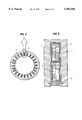
- FIG. 5 is a transverse the cross section of the rotating electric stator of the present invention.
- FIG. 6 is an enlarged radial cross section of the rotating electric stator of FIG. 5.
- FIG. 7 is a perspective view depicting a rotating machine forming one example of the present invention.
- thermosetting resin composition having a viscosity of 5 poise or more at 25° C., preferably 10 poise or more at 25° C., and a viscosity of 5 poise or less at 60° C. and comprising
- a metal acetonate curing catalyst represented by the Chemical formula 2 ##STR5## (wherein X and Y represent methyl group or phenyl group; Me represents Mn, Co, Zn or Zr; and "n" represents the coordination number) at 0.1 to 5 parts by weight per 100 parts by weight of the epoxy resins, wherein the ratio of the numbers of the epoxy resins used is 1 to 4, the ratio being represented by the following relationship:
- Ratio of numbers of epoxy resins ⁇ [molar number of (b) used] ⁇ [number of epoxy resins in 1 mole of (b)] ⁇ [molar number of (a) used] ⁇ [number of epoxy resins in 1 mole of (a)] ⁇ .
- thermosetting resin composition In the electrically insulated coils produced by the single impregnation process comprising impregnating and curing an electrically insulated coil with an insulating tape base material wound around a stack of insulated conductors formed into a defined coil shape with a thermosetting resin composition, and thereafter placing the coil into an iron core slot and the total impregnation process comprising incorporating an electrically insulated coil with an insulating tape base material wound around a stack of insulated conductors formed in a defined coil shape into an iron core slot, inserting a wedge into the external circumferential groove of the iron core slot to connect the electrical insulating coil to the external end part of the iron core, and impregnating and curing the electrically insulated coil and the iron core slot in their integrated state with a thermosetting resin composition, wherein as the thermosetting resin composition, use is made of a thermosetting resin composition having at a viscosity of 5 poise or more, preferably 10 poise or more, at 25° C. and a viscosity of 5 poise or
- Ratio of numbers of epoxy resins ⁇ [molar number of (b) used] ⁇ [number of epoxy resins in 1 mole of (b)] ⁇ [molar number of (a) used] ⁇ [number of epoxy resins in 1 mole of (a)] ⁇ , whereby the electrical insulated coil can exhibit a high heat resistance and a high thermal conductivity with less flow of the thermosetting resin composition.
- a first aspect of the present invention is an invention relates to a thermosetting resin composition being at a viscosity of 5 poise or more preferably 10 poise or more, at 25° C. and a viscosity of 5 poise or less at 60° C. and comprising
- Ratio of numbers of epoxy resins ⁇ [molar number of (b) used] ⁇ [number of epoxy resins in 1 mole of (b)] ⁇ [molar number of (a) used] ⁇ [number of epoxy resins in 1 mole of (a)] ⁇ .
- a second aspect of the present invention relates to a thermosetting resin composition having a viscosity of 5 poise or more at 25° C., preferably 10 poise or more at 25° C., and a viscosity of 5 poise or less at 60° C. and comprising
- Ratio of numbers of epoxy resins ⁇ [molar number of (b) used] ⁇ [number of epoxy resins in 1 mole of (b)] ⁇ [molar number of (a) used] ⁇ [number of epoxy resins in 1 mole of (a)] ⁇ .
- a third aspect of the present invention relates to an electrically insulated coil produced by winding an insulating tape base material around a stack of insulated conductors formed into a defined coil shape and thereafter impregnating and curing the electrically insulated coil with a thermosetting resin composition, wherein as the thermosetting resin composition, use is made of a thermosetting resin composition having at a viscosity of 5 poise or more at 25° C., preferably 10 poise or more at 25° C. and a viscosity of 5 poise or less at 60° C., and comprising
- Ratio of numbers of epoxy resins ⁇ [molar number of (b) used] ⁇ [number of epoxy resins in 1 mole of (b)] ⁇ [molar number of (a) used] ⁇ [number of epoxy resins in 1 mole of (a)] ⁇ .
- a fourth aspect of the present invention relates to an electrically insulated coil of a stator for a rotating machine, produced by incorporating into an iron core slot an electrically insulated coil produced by winding an insulating tape base material around a stack of insulated conductors formed into a defined coil shape, inserting a wedge into the external circumferential groove of the iron core slot to connect the electrically insulated coil to the external end part of the iron core, and thereafter impregnating, in their integrated state, the electrically insulated coil and the iron core slot with a thermosetting resin composition, and then hardening the resin, wherein as the thermosetting resin composition, use is made of a thermosetting resin composition having a viscosity of 5 poise or more at 25° C., preferably 10 poise or more at 25° C. and a viscosity of 5 poise or less at 60° C., and comprising
- Ratio of numbers of epoxy resins ⁇ [molar number of (b) used] ⁇ [number of epoxy resins in 1 mole of (b) ⁇ ] ⁇ [molar number of (a) used] ⁇ [number of epoxy resins in 1 mole of (a)] ⁇ .
- a fifth aspect of the present invention relates to an electrically insulated coil of a stator for a rotating machine, produced by incorporating into an iron core slot an electrically insulated coil produced by winding an insulating tape base material around a stack of insulated conductors formed into a defined coil shape, inserting a wedge into the external circumferential groove of the iron core slot to connect the electrical insulating coil to the external end part of the iron core, and thereafter impregnating and curing the electrically insulated coil and the iron core slot in their integrated state with a thermosetting resin composition, wherein as the insulating tape base material, use is made of an insulating tape base material having a heat conductivity as high as 0.3 to 0.8 W/mK and
- thermosetting resin composition wherein as the thermosetting resin composition, use is made of a thermosetting resin composition having at a viscosity of 5 poise or more, preferably 10 poise or more, at 25° C. and a viscosity of 5 poise or less at 60° C. and comprising
- Ratio of numbers of epoxy resins ⁇ [molar number of (b) used] ⁇ [number of epoxy resins in 1 mole of (b)] ⁇ [molar number of (a) used] ⁇ [number of epoxy resins in 1 mole of (a)] ⁇ .
- a sixth aspect of the present invention relates to an electrically insulated coil for a stator of a rotating machine, produced by incorporating into an iron core slot an electrically insulated coil produced by winding an insulating tape base material around a stack of insulated conductors formed into a defined coil shape together with a semiconductive slot liner, inserting a wedge into the external circumferential groove of the iron core slot to connect the electrical insulating coil to the external end part of the iron core, and thereafter impregnating and curing the electrical insulating coil and the iron core slot in their integrated state with a thermosetting resin composition,
- the semiconductive slot liner use is made of a highly heat-conductive, semiconductive slot liner with a heat conductivity as high as 0.3 to 1.0 W/mK and a surface resistance of 0.2 to 100 k ⁇ ;
- thermosetting resin composition wherein as the thermosetting resin composition, use is made of a thermosetting resin composition having a viscosity of 5 poise or more, preferably 10 poise or more, at 25° C. and a viscosity of 5 poise or less at 60° C. and comprising
- Ratio of numbers of epoxy resins ⁇ [molar number of (b) used] ⁇ [number of epoxy resins in 1 mole of (b)] ⁇ [molar number of (a) used] ⁇ [number of epoxy resins in 1 mole of (a)] ⁇ .
- a seventh aspect of the present invention relates to a rotating machine comprising a stator and a rotor, produced by incorporating into an iron core slot an electrical insulating coil produced by winding an insulating tape base material around a stack of insulated conductors formed into a defined coil shape, inserting a wedge into the external circumferential groove of the iron core slot to connect the electrical insulating coil to the external end part of the iron core, and thereafter impregnating and curing the electrical insulating coil and the iron core slot in their integrated state with a thermosetting resin composition,
- thermosetting resin composition wherein as the thermosetting resin composition, use is made of a thermosetting resin composition having a viscosity of 5 poise or more, preferably 10 poise or more, at 25° C. and a viscosity of 5 poise or less at 60° C. and comprising
- Ratio of numbers of epoxy resins ⁇ [molar number of (b) used] ⁇ [number of epoxy resins in 1 mole of (b)] ⁇ [molar number of (a) used] ⁇ [number of epoxy resins in 1 mole of (a)] ⁇ .
- Any polyfunctional compound containing three or more p-(2,3-epoxypropoxy)phenyl groups and a group represented by the previously set forth Chemical formula 1 may be used, with no specific limitation, as the polyfunctional epoxy resin containing three or more p-(2,3-epoxypropoxy)phenyl groups and a group represented by the previously set forth Chemical formula 1; in accordance with the present invention.
- Such compound includes for example polyfunctional epoxy resins such as tris[p-(2,3-epoxypropoxy)phenyl]methane, 1,1,2-tris[p-(2,3-epoxypropoxy)phenyl]ethane, 1,1,2-tris[p-(2,3-epoxypropoxy)phenyl]propane, 1,1,3-tris[p-(2,3-epoxypropoxy)phenyl]propane, 1,1,3-tris[p-(2,3-epoxypropoxy)phenyl]butane, 1,1,2,2-tetrakis[p-(2,3-epoxypropoxy)phenyl]ethane, 1,1,3,3-tetrakis[p-(2,3-epoxypropoxy)phenyl]propane and the like.
- polyfunctional epoxy resins such as tris[p-(2,3-epoxypropoxy)phenyl]methane, 1,1,2-tris[p-(2,3-epoxypropoxy
- the epoxy resin with the naphthalene backbone represented by the Chemical formula 3, includes diglycidyl ether of dihydroxynaphthalenes such as 1,6-dihydroxynaphthalene, 1,2-dihydroxynaphthalene, 1,3-dihydroxynaphthalene, 1,4-dihydroxynaphthalene, 1,5-dihydroxynaphthalene, 1,7-dihydroxynaphthalene, 1,8-dihydroxynaphthalene, 2,3-dihydroxynaphthalene, 2,6-dihydroxynaphthalene, and 2,7-dihydroxynaphthalene; triglycidyl ether of trihydroxynaphthalenes such as 1,2,3-trihydroxynaphthalene, 1,2,4-trihydroxynaphthalene, 1,2,5-trihydroxynaphthalene, 1,2,6-trihydroxynaphthalene, 1,2,7-trihydroxynaphthalene, 1,2,8-trihydroxynaphthalene, 1,3,5-tri
- the epoxy resin with the naphthalene backbone represented by the Chemical formula 4, includes dihydroxynaphthalene, trihydroxynaphthalene and tetrahydroxynaphthalene singly or polyglycidyl ether of a novolak type resin of a mixture thereof with formaldehyde. Additionally, the dihydroxynaphthalene, trihydoxynaphthalene and tetrahydroxynaphthalene alone or polyglycidyl ether of a novolak-type epoxy resin of a mixture thereof with acetoaldehyde or the like, is also useful.
- polyglycidyl ether of a novolak type resin comprising a mixture of the dihydroxynaphthalene, trihydroxynaphthalene and tetrahydroxynaphthalene with phenol, aminophenol, cresol and the like and formaldehyde
- polyglycidyl ether of a novolak type resin comprising a mixture of the dihydroxynaphthalene, trihydroxynaphthalene, and tetrahydroxynaphthalene with phenol, aminophenol, cresol and the like and acetoaldehyde and the like, is also useful.
- a mixture of those resins represented by the Chemical formulas 3, 4 and 5 is also effective. Among them, preference is given to the epoxy resins represented by the Chemical formula 4 and 5 and a mixture of the resins with 1,6-dihydroxynaphthalene diglycidyl ether, from the aspect of heat resistance and viscosity. If necessary, additionally, the addition of amines and phenols or a modification thereof may satisfactorily be carried out.
- Any bifunctional epoxy resin containing two epoxy groups may be used satisfactorily, with no specific limitation, in accordance with the present invention.
- Such a compound includes, for example, diglycidyl ether of bisphenol A, diglycidyl ether of bisphenol F, diglycidyl ether of bisphenol AD, diglycidyl ether of hydrogenated bisphenol A, diglycidyl ether of 2,2-(4-hydroxyphenyl)nonadecane, diphenyl ether of 4,4'-bis(2,3-epoxypropyl)diphenyl ether, 3,4-epoxycyclohexylmethyl-(3,4-epoxy)cyclohexane carboxylate, 4-(1,2-epoxypropyl)-1,2-epoxycylohexane, 2-(3,4-epoxy)cyclohexyl-5,5-spiro(3,4-epoxy)cyclohexane-m-dioxane, 3,4-e
- bifunctional epoxy resins containing two p-(2,3-epoxypropoxy)phenyl groups such as diglycidyl ether of bisphenol A, diglycidyl ether of bisphenol F and diglycidyl ether of bisphenol AD, are useful from the aspect of heat resistance and viscosity.
- the metal acetonate curing catalysts represented by the previously set forth Chemical formula 2, to be used in accordance with the present invention include curing catalysts selected from the group consisting of manganese (III) acetylacetonate, manganese (III) benzoylacetonate, cobalt (II) acetylacetonate, cobalt (III) acetylacetonate, cobalt (II) benzoylacetonate, zinc (II) acetylacetonate, chromium (III) acetylacetonate, titanyl acetylacetonate, aluminium (III) acetylacetonate, nickel (II) acetylacetonate, vanadium (III) acetylacetonate, zirconium (IV) acetylacetonate, sodium (I) acetylacetonate, potassium (I) acetylacetonate and a mixture thereof.
- the metal acetonate curing catalysts may be blended at any ratio, with no specific limitation, but preferably are blended at 0.1 to 5 parts by weight per 100 parts by weight of the epoxy resins. If the amount is much, however, the pot life tends to be shorter, while the resin may tend to flow if the amount is too less.
- Any general acid anhydride may be used, with no specific limitation, in accordance with the present invention.
- Such a compound includes for example methylhexahydrophthalic anhydride, hexahydrophthalic anhydride, methyltetrahydrophthalic anhydride, tetrahyd-ophthalic anhydride, nadic anhydride, methylnadic anhydride, dodecylsuccinic anhydride, succinic anhydride, octadecylsuccinic anhydride, maleic anhydride, benzophenone tetracarboxylic anhydride singly, or a mixture thereof.
- the compound includes nadic anhydride and methylnadic anhydride from the aspect of heat resistance.
- the ratio of blending of an acid anhydride into the epoxy resin is preferably at 0.8 to 1.2 in equivalent ratio.
- the ratio of a polyfunctional epoxy resin with three or more functional groups blended with a bifunctional epoxy resin is not with specific limitation, but preferably, 0.1 to 19 parts by weight of a bifunctional epoxy resin is blended with one part by weight of a polyfunctional epoxy resin. If the polyfunctional epoxy resin is much, the viscosity prior to curing tends to increase, involving the tendency that the resulting composition may turn hard and fragile; adversely, when the bifunctional epoxy resin is much, the viscosity decreases, while the heat resistance tends to be reduced. From the aspect of the compatibility between viscosity and heat resistance, effectively, 1 to 9 parts by weight of a bifunctional epoxy resin should be blended with one part by weight of a polyfunctional epoxy resin, in particular.
- the ratio of blending (a) a polyfunctional epoxy resin containing three or more p-(2,3-epoxypropoxy)phenyl groups and a group represented by the previously set forth Chemical formula 1, or an epoxy resin with a naphthalene backbone or an epoxy resin with an anthracene backbone, such as diglycidyl ether of anthracene diol and triglycidyl ether of anthracene triol, represented by the previously set forth Chemical formula 3, 4 or 5 to (b) a bifunctional epoxy resin containing two p-(2,3-epoxypropoxy)phenyl groups, is represented by the following relationship:
- Ratio of numbers of epoxy resins ⁇ [molar number of (b) used] ⁇ [number of epoxy resins in 1 mole of (b)] ⁇ [molar number of (a) used] ⁇ [number of epoxy resins in 1 mole of (a)] ⁇ . From the aspect of heat resistance, viscosity and pot life, preferably, the ratio of the numbers of the epoxy resins to be used is 1 to 4.
- the viscosity of the thermosetting resin composition is 5 poise or more, preferably 10 poise or more, at 25° C. and 5 poise or less at 60° C.
- the insulating base material to be used in accordance with the present invention includes a mica sheet, a polyimide sheet, a polyamide sheet, a polyparabenic acid sheet, a polyimide ether sheet, a polyether ether ketone sheet, a polysulfide sheet and the like.
- Mica includes for example non-calcined soft composite mica, non-calcined hard composite mica, calcined hard composite mica, calcined soft composite mica, synthetic mica or aramide-mixed mica.
- highly heat-conductive mica with inorganic fillers, such as silica, alumina, and boron nitride, dispersed therein, is also useful, as described in Japanese Patent Publication No. Sho 56-38006.
- Inorganic fillers can be also added to the binder.
- Mica in itself has a good insulating performance, but a lower strength, and therefore, mica can be wound around a conductor only with much difficulty.
- mica should be attached to a reinforcing material by means of a binder.
- the reinforcing material for mica includes for example glass fiber, aramide, aramide-mixed paper, films of polyamide imide, polyester, polyimide ether, polyether ether ketone, polyether sulfone, polyparabenic acid, polysulfide or polyimide; and films with a higher heat conductivity, produced by filling silica or alumina into the aforementioned films.
- glass fiber and polyimide film are preferable as the reinforcing material for mica from the aspect of heat resistance.
- silica- or alumina-filled glass fiber and polyimide film with an increased thermal conductivity are preferable.
- any binder may be satisfactory as long as the binder can bond mica to the reinforcing material.
- Such a binder includes epoxy resin, silicone resin, alkyd resin, polyester resin, epoxy ester resin and the like. From the aspect of heat resistance, among them, a binder which is reactive with the thermosetting resin of the present invention is particularly preferable.
- the insulating base material is hard, additionally, the insulating base material may satisfactorily be softened for use.
- the binder should be contained in any amount in the insulating base material with no specific limitation, but preferably is provided at 3 to 40% by weight, particularly at 5 to 20% by weight. If the binder content is high, the amount of the thermosetting resin composition in the impregnation is so small that the heat resistance tends to decrease. If the binder content is less, alternatively, the adhesive strength is so deteriorated that the insulating base material tends to peel off, which means that the base material is able to be wound back on a conductor only with much difficulty.
- a surfactant includes for example silane surfactants such as ⁇ -chloropropyltrimethoxysilane, vinyltrichlorosilane, vinyltriethoxysilane, vinyltrimethoxysilane, vinyl tris ( ⁇ -methoxyethoxy) silane, ⁇ -methacryloxypropyltrimethoxysilane, ⁇ -(3,4-epoxycyclohexyl)ethyltrimethoxysilane, ⁇ -glycidoxypropyltrimethoxysilane, ⁇ -mercaptopropyltrimethoxysilane, ⁇ -aminopropyltriethoxysilane, N- ⁇ -(aminoethyl)- ⁇ -aminopropy
- ⁇ -glycidoxypropyltrimethoxysilane preference is given to ⁇ -glycidoxypropyltrimethoxysilane, ⁇ -3,4-epoxycylohexyl)ethyltrimethoxysilane, ⁇ -mercaptopropyltrimethoxysilane, ⁇ -aminopropyltriethoxysilane, N- ⁇ -(aminoethyl)- ⁇ -aminopropyltrimethoxysilane, isopropylisostearoyltitanate, isopropyltrioctanoyltitanate, ethyl acetoacetate aluminium diisopropylate and aluminium tris(ethyl acetoacetate). Two or more of the surfactants may satisfactorily be mixed together.
- monoepoxy resins such as cyclohexene vinyl monooxide, octylene oxide, butyl glycidyl ether, styrene oxide, phenylglycidyl ether, glycidyl methacrylate, and allyl glycidyl ether may be added as a diluent.
- diluents have an effect of lowering viscosity, which is accompanied by the decrease of heat resistance. Therefore, the amount of the diluents should be suppressed to a low level.
- a filler hydrated alumina, hydrated magnesium, calcium carbonate, zirconium silicate, calcium silicate, talc, clay, mica, glass fiber powder and the like may be added as the filler, other than silica powder, quartz glass powder and alumina powder.
- PDGON polymerized 1,6-diglycidyloxynaphthalene
- epoxy equivalent 250 and softening point of 67° C.
- GONDGONM 1-(2-glycidyloxy-1-naphthyl)-1-(2',7'-diglycidyloxy-1-naphthyl)methane; epoxy equivalent of 187 and softening point of 75° C.
- BDGON 1,1-bis(2,7-diglycidyloxy-1-naphthyl)methane; epoxy equivalent of 161 and softening point of 91° C.
- BDGOE 1,1-bis(2,7-diglycidyloxy-1-naphthyl)ethane
- PGENCN polyglicidyl ether of novolak of a mixture of cresol and 2-hydroxynaphthalene; epoxy equivalent of 225 and softening point of 84° C.
- TKEPPE 1,1,2,2-tetrakis[p-(2,3-epoxypropoxy)phenyl]methane; epoxy equivalent of 192
- TEPPM 1,1,3-tris[p-(2,3-epoxypropoxy)phenyl]methane; epoxy equivalent of 161
- thermosetting resin compositions 1. Preparation of thermosetting resin compositions and assessment of the performance
- Epoxy resins, curing agents and curing catalysts were mixed together at the mixing ratios shown in Tables 1 to 8, prior to sufficient dissolution under agitation and heating. Then, the viscosity increased, until the viscosity exceeded 5 P at 60° C. Therefore, the amounts of curing catalysts as described in the Tables were added to parts of the curing agents, prior to heating to 100 to 120° C. for agitation and dissolution, and the resulting mixtures were left to stand at room temperature. During dissolution under heating, parts of the curing agents were vaporized with a stimulating odor. Then, the remaining curing agents and epoxy resins were added to the mixtures for sufficient agitation. In all of the Examples, the viscosity was 5 P or less at 60° C.
- the curing catalysts in the amounts shown in the Tables with parts of the epoxy resins and heating the catalysts to 100 to 120° C. under agitation for dissolution, alternatively, the resulting mixtures were left at ambient temperature. Then, the remaining epoxy resins and the remaining curing agents were added to the mixtures for sufficient agitation. In all of the Examples, the viscosity was 5 P or less at 60° C.
- the method for mixing the curing catalysts preference is given to a method comprising dissolving the catalysts in the curing agents or the epoxy resins under heating and subsequently adding the remaining parts as shown in the Tables to the resulting mixtures. For environmental hygiene and for mixing the calculated amounts to be mixed, most preferably, the curing catalysts are dissolved in the epoxy resins under heating.
- the viscosity at 25° C. and 60° C., the pot life and the heat-resistant temperature coefficient of a thermosetting resin composition are shown in the Tables, when a curing catalyst was dissolved in the epoxy resins.
- the viscosity was measured by a B-type viscometer; the pot life was defined as a period in a day until the initial viscosity of the thermosetting resin composition increased by two-fold.
- the heat-resistant temperature was determined according to the IEC Pub.216. More specifically, cured matters each of a size of 2 ⁇ 50 ⁇ 50 mm were left to stand in air-circulation type thermostats individually maintained at 270° C., 250° C.
- thermosetting resin compositions for impregnating electric appliances were drawn out at a predetermined interval, to measure the weight to calculate the decrement due to heating.
- the time required for the decrement due to heating to reach 10% by weight was determined, which was defined as life. Plotting then the life vs. the inverse number of the absolute temperature, a linear relation was established in any case. Extrapolating the line, the temperature for the life to reach 20,000 hours was determined and defined as the heat-resistant temperature.
- the heat resistance of the thermosetting resin compositions for impregnating electric appliances is determined on the basis of the heat-resistant temperature.
- thermosetting resin compositions comprising
- an epoxy resin with a naphthalene backbone represented by the previously set forth Chemical formula 3, 4 or 5 or an epoxy resin with an anthracene backbone, such as diglycidyl ether of anthracene diol and triglycidyl ether of anthracene triol;
- Ratio of numbers of epoxy resins ⁇ [molar number of (b) used] ⁇ [number of epoxy resins in 1 mole of (b)] ⁇ [molar number of (a) used] ⁇ [number of epoxy resins in 1 mole of (a)] ⁇ ,
- Table 3 indicates that when the ratio (b)/(a) as the ratio of the numbers of the epoxy resins used is 1 to 4 as represented by the following relationship, provided that (b) is a bifunctional epoxy resin containing two p-(2,3-eposypropoxy)phenyl groups and (a) is an epoxy resin with a naphthalene backbone or an epoxy resin with an anthracene backbone, such as diglycidyl ether of anthracene diol and triglycidyl ether of anthracene triol, represented by the previously set forth Chemical formula 3, 4 or 5;
- Ratio of numbers of epoxy resins ⁇ [molar number of (b) used] ⁇ [number of epoxy resins in 1 mole of (b)] ⁇ [molar number of (a) used] ⁇ [number of epoxy resins in 1 mole of (a)] ⁇ , the heat-resistant temperature is above 200° C. and the viscosity then is 5 poise or more at 25° C. and 5 poise or less at 60° C.; and when the ratio is 2 to 3, the heat-resistant temperature is larger, preferably. If the (b)/(a) ratio is 0.7, the heat-resistant temperature is small while the viscosity is too small, which causes a tendency for the resin flow out during impregnation and curing of coil.
- the viscosity then is too high, which causes a tendency for the impregnation with the resin to hardly occur. It can be said that the ratio outside the range of 1 to 4 is not preferable.
- Tables 4 to 7 indicate that manganese (III) acetylacetonate, manganese (III) benzoylacetonate, cobalt (II) acetylacetonate, cobalt (III) acetylacetonate, cobalt (II) benzoylacetonate, titanyl acetylacetonate, vanadium (III) acetylacetnaate, zirconium (IV) acetylacetnaate and the like are preferable as the curing catalyst.
- thermosetting resin composition comprises (b) a bifunctional epoxy resin containing two p-(2,3-epoxypropoxy)phenyl groups and (a) a polyfunctional epoxy resin containing three or more p-(2,3-epoxypropoxy)phenyl groups and a group represented by the previously set forth Chemical formula 1, provided that the (b)/(a) ratio as the ratio of the numbers of the epoxy resins used is 1 to 4, the ratio being represented by the following relationship:
- thermosetting resin composition has a heat-resistant temperature of 200° C. or more and is at a viscosity of 5 poise or more at 25° C. and 5 poise or less at 60° C. and that the heat-resistant temperature thereof is high within a range of 2 to 3 as the (b)/(a) ratio.
- the heat-resistant temperature is small while the viscosity is too small, which causes a tendency for the resin to flow out during impregnation and curing of coil. If the (b)/(a) ratio is 5.0, alternatively, the viscosity then is too high, which causes a tendency for the impregnation with the resin to be hardly effected. It can be said that the ratio outside the range of 1 to 4 is not preferable.
- Table 6 indicates that the metal acetonate curing catalyst represented by the previously set forth Chemical formula 2 to be used in accordance with the present invention is contained at 0.1 to 5 parts by weight per 100 parts by weight of the epoxy resin. If the amount is too much, the pot life tends to be shortened; whereas, if the amount is too small, the curing performance is deteriorated, involving the tendency of the resin to flow.
- Table 8 indicates that preference is given as the curing agent to methylhexahydrophthalic anhydride, methyltetrahydrophthalic anhydride, tetrahydrophthalic anhydride, and methylnadic anhydride; and that the acid anhydride should preferably be mixed with the epoxy resin at a ratio as an equivalent ratio of 0.8 to 1.2, from the aspect of heat resistance.
- a binder solution was prepared by adjusting the concentration of TEPPM by means of methyl ethyl ketone so that the non-volatile part of the solution might be at 50%.
- a calcined soft composite mica filled with an aromatic polyamide fibrid was attached to glass cloth, while the solvent was vaporized simultaneously.
- the binder contents in the resulting glass-reinforced mica tape (insulating tape base material) corresponded to the non-volatile parts, and therefore, three types of the insulating base material were thus prepared at the binder contents of about 5, 20 and 30% by weight (based on the total weight of the insulating tape base material). Cutting these types of the insulating tape base material, tapes of a 25-mm width were produced.
- a binder solution was prepared by adjusting the concentrations of POGEPN and alumina by means of methyl ethyl ketone so that the non-volatile parts thereof might be at 50%.
- a calcined soft composite mica filled with an aromatic polyamide fibrid was attached to glass cloth, while the solvent was vaporized simultaneously.
- the binder contents in the resulting glass-reinforced mica tape (insulating tape base material) corresponded to the non-volatile parts, and therefore, three types of the insulating base material were thus prepared at the binder contents of about 5, 20 and 30% by weight (based on the total weight of the insulating tape base material). Cutting these types of the insulating tape base material, tapes of a 25-mm width and with a heat conductivity of 0.3 to 0.8 W/mK were produced.
- a binder solution was prepared by adjusting the concentrations of POGEPN and alumina by means of methyl ethyl ketone. By using the binder solution then, a calcined soft composite mica filled with an aromatic polyamide fibrid and alumina was attached to glass cloth, while the solvent was vaporized simultaneously.
- the binder contents in the resulting glass-reinforced mica tape (insulating tape base material) corresponded to the non-volatile parts, and therefore, three types of the insulating base material were thus prepared at the binder contents of about 5, 20 and 30% by weight (based on the total weight of the insulating tape base material). Cutting these types of the insulating tape base material, tapes of a 25-mm width and with a heat conductivity of 0.3 to 0.8 W/mK were produced.
- a binder solution was prepared by adjusting the concentrations of TEPPM and alumina by means of methyl ethyl ketone so that the non-volatile part of the solution might be at 50%.
- a calcined soft composite mica filled with an aromatic polyamide fibrid was attached to glass cloth, while the solvent was vaporized simultaneously.
- the binder contents in the resulting glass-reinforced mica tape (insulating tape base material) corresponded to the non-volatile parts, and therefore, three types of the insulating base material were thus prepared at the binder contents of about 5, 20 and 30% by weight (based on the total weight of the insulating tape base material). Cutting these types of the insulating tape base material, tapes of a 25-mm width and with a heat conductivity of 0.3 to 0.8 W/mK were produced.
- a binder solution was prepared by adjusting the concentrations of TEPPM and alumina by means of methyl ethyl ketone so that the non-volatile part of the solution might be at 50%.
- a calcined soft composite mica filled with an aromatic polyamide fibrid and alumina was attached to polyimide film, while the solvent was vaporized simultaneously.
- the binder contents in the resulting glass-reinforced mica tape (insulating tape base material) corresponded to the non-volatile parts, and therefore, three types of the insulating base material were thus prepared at the binder contents of about 5, 20 and 30% by weight (based on the total weight of the insulating tape base material). Cutting these types of the insulating tape base material, tapes of a 25-mm width and with heat conductivity of 0.3 to 0.8 W/mK were produced.
- FIG. 1 is a perspective, partially cutout view of an electrically insulated coil of the type which was measured.
- Insulating layer 2 which is wound around and arranged on a stack of insulated conductors 1, is impregnated and cured with a thermosetting resin composition, and thus, these elements are integrated together.
- One cycle of a heating and moisture absorption test at 270° C. for 24 hours and 40° C. for 24 hours in 95% RH was carried out for 10 cycles.
- the dissipation factor "tan ⁇ " and insulation resistance were measured.
- the tan ⁇ was 10% or less after the 10 cycles.
- the insulation resistance was 10 12 ⁇ or more.
- the tan ⁇ after the 10 cycles was 20% or more.
- the insulation resistance was 10 10 ⁇ or less.
- a test piece of the insulating layer alone was cut out in a size of 10-mm width and 60-mm length.
- the bending strength thereof was measured at 25° C. under a load on the central part between two supported points at an interval of 40 mm.
- the bending strength after 24-hr immersion of the test piece in water at 40° C. was measured to determine the strength retention rate.
- the rate was 80% or more.
- the rate was 60% or less.
- the temperature characteristics of the Dissipation factor "tan ⁇ " of the electrical insulating coil produced in Example 1 are shown as the relation between the temperature (°C; on the axis of abscissa) and the tan ⁇ (%; on the axis of ordinate) in the graph shown in FIG. 2.
- "A” represents the characteristic curve at an initial insulation stage; and "B” represents the characteristic curve after 1000-hr heating at 250° C. in the Example 1.
- FIG. 3 is a thermal endurance graph depicting the relation between the heat-resistant life (h; on the axis of ordinate) of an electrical insulating coil of the present invention and temperature (°C; on the axis of abscissa).
- the coil of the present invention is highly heat resistant in the heat-resistant life at a motorette test according to U.S. Standard IEEE. NO. 275, and it is indicated that the coil is usable at 200° C. or more.
- the coils of the present invention are highly heat resistant in the heat-resistant life at a motorette test according to U.S. Standard IEEE. No. 27s, and it is indicated that the coils are usable at 200° C. or more.
- a tape with a higher heat conductivity, if used as the insulating tape base material, can have better thermal dispersion, which enables the production of a small-scale and light-weight rotating machine at a low cost.
- a heat conductivity of 0.3 to 0.8 W/mK is effective
- thermosetting resin compositions of the Comparative Examples showed a poor voltage profile as a dissipation factor with a larger corona discharge, so that the heat-resistant life was at 190° C. or less as determined by the motorett test.
- thermosetting resin compositions were almost not filled in between the electrically insulated coils and the iron core slots, resulting in a poor voltage profile as a dissipation factor and a larger corona discharge.
- coil 3 as shown in FIG. 4 was prepared. As shown in FIG. 5, the coil 3 was incorporated together with a slot liner 4 into the slot of an iron core 5, followed by insertion of a wedge 6 on the external circumferential groove of the iron core slot. Subsequently connecting the electrical insulating coil at the external end part of the iron core and impregnating in vacuo the electrically insulated coils and the iron core slots together at their integrated state with a thermosetting resin composition in Tables 1 to 8, prior to heating at 175° C. for 4 hours, a stator of rotating machine was produced.
- thermosetting resin compositions were also completely filled in between the electrical insulating coils and the iron core slots.
- thermosetting resin compositions were not filled in between the electrically insulated coils and the iron core slots, resulting in a poor voltage profile as a dielectric tangent and a larger corona discharge.
- coil 3 as shown in FIG. 4 was prepared.
- the coil 3 was incorporated together with a highly heat-conductive, semiconductive slot liner 4 with a heat conductivity of 0.3 to 1.0 W/mK and surface resistance of 0.2 to 100 k ⁇ into the slot of iron core 5, followed by insertion of wedge 6 on the external circumferential groove of the iron core slot.
- thermosetting resin compositions were completely filled in between the electrically insulated coils and the iron core slots.
- thermosetting resin compositions were not filled in between the electrical insulating coils and the iron core slots, resulting in a poor voltage profile as a dielectric tangent and a larger corona discharge.
- the stators of a rotating machine wound with an insulating tape base material with a heat conductivity as high as 0.3 to 0.8 W/mK has a greater thermal dispersion performance than the stators of a rotating machine wound with an insulating tape base material with a heat conductivity of 0.2 W/mK or less; if these stators are of the same size, the stator wound with the material with a heat conductivity of 0.3 to 0.8 W/mK can pass a larger power and a higher electric current; at the same power level, the equipment therefor can be made small and light in weight, resulting in a cost reduction.
- coil 3 as shown in FIG. 4 was prepared. As shown in FIG. 5, the coil 3 was incorporated together with a highly heat-conductive, semiconductive slot liner 4 with a heat conductivity of 0.3 to 1.0 W/mK and a surface resistance of 0.2 to 100 k ⁇ into the slot of iron core 5, followed by insertion of wedge 6 on the external circumferential groove of the iron core slot.
- thermosetting resin compositions were completely filled in between the electrical insulating coils and the iron core slots.
- any of the Comparative Examples alternatively, almost all cured matters of the thermosetting resin compositions were not filled in between the electrical insulating coils and the iron core slots, resulting in a poor voltage profile as a dielectric tangent and a larger corona discharge.
- a stator of a rotating machine using a highly heat-conductive, semi electrically conductive slot liner with a heat conductivity as high as 0.3 to 0.8 W/mK and with a surface resistance of 0.2 to 100 k ⁇ has a higher thermal dispersion performance than a stator of a rotating machine wound with an insulating tape base material with a heat conductivity of 0.2 W/mK or less; if these stators are of the same size, the stator using a highly heat-conductive, semi electrically conductive slot liner with a heat conductivity as high as 0.3 to 0.8 W/mK and with a surface resistance of 0.2 to 100 k ⁇ can pass a larger power and a higher electric current; at the same power level, the equipment can be made small and light in weight, with a cost reduction.
- a stator of a rotating machine using a highly heat-conductive, semiconductive slot liner with a heat conductivity as high as 0.3 to 1.0 W/mK and a surface resistance of 0.1 to 100 k ⁇ and using an insulating tape base material with a high heat conductivity of 0.3 to 0.8 W/mK has the highest thermal dispersion performance; at the same size, the stator can pass a larger power and a higher electric current; and, at the same power level, the equipment can be made small and light in weight, with cost reduction.
- an electric motor was prepared from a combination of a stator 7 as produced in Example 57 to 59 with an armature coil 8.
- the stator using a highly heat-conductive, semi electrically conductive slot liner with a heat conductivity of 0.3 to 1.0 W/mK and with a surface resistance of 0.2 to 100 k ⁇ and using a highly heat-conductive insulating tape base material with a heat conductivity of 0.3 to 0.8 W/mK has an improved thermal dispersion performance by 20% or more, compared with other rotating machines, with a resultant small machine size represented by a 25% or more reduction in size and a weight reduction of 23% or more.
- less materials are required, whereby the cost can be reduced distinctively, and additionally, only a smaller equipment space is needed.
- thermosetting resin composition having a viscosity of 5 poise or more, preferably 10 poise or more at 25° C., and a viscosity of 5 poise or less at 60° C., comprising
- Ratio of numbers of epoxy resins ⁇ [molar number of (b) used] ⁇ [number of epoxy resins in 1 mole of (b)] ⁇ [number of (a) used] ⁇ [number of epoxy resins in 1 mole of (a)] ⁇ .
Landscapes
- Chemical & Material Sciences (AREA)
- Polymers & Plastics (AREA)
- Organic Chemistry (AREA)
- Health & Medical Sciences (AREA)
- Chemical Kinetics & Catalysis (AREA)
- Medicinal Chemistry (AREA)
- Physics & Mathematics (AREA)
- Engineering & Computer Science (AREA)
- Power Engineering (AREA)
- Spectroscopy & Molecular Physics (AREA)
- Epoxy Resins (AREA)
- Insulation, Fastening Of Motor, Generator Windings (AREA)
- Manufacture Of Motors, Generators (AREA)
- Compositions Of Macromolecular Compounds (AREA)
- Organic Insulating Materials (AREA)
Abstract
A highly thermal-conductive and thermal-resistant electrically insulated coil with less outflow of a thermosetting resin composition can be produced, to provide a small-scale, light-weight rotating machine with high power. The thermosetting resin composition comprises (a) a polyfunctional epoxy resin containing three or more p-(2,3-epoxypropoxy) phenyl groups and a group represented by the Chemical formula 1; or an epoxy resin with a naphthalene backbone, represented by the Chemical formula 3, 4 or 5 or an epoxy resin with an anthracene backbone, such as diglycidyl ether of anthracene diol and triglycidyl ether of anthracene triol; (b) a bifunctional epoxy resin containing two p-(2,3-epoxypropoxy) phenyl groups; (c) an acid anhydride curing agent; and (d) a metal acetonate curing catalyst represented by the Chemical formula 2 at 0.1 to 5 parts by weight per 100 parts by weight of the epoxy resins.
Description
The present invention relates to an electrically insulated coil, having a high shear strength and a high heat resistance and a high withstand voltage, wherein a thermosetting resin composition of a repeatedly usable one-component epoxy resin is used, and to an electric rotating machine using the coil. The invention also relates to a method for producing a totally impregnated rotating coil.
Demands for making high-voltage rotating machines, such as electric vehicles and induction motors for general industries, with a small scale, a light weight and a low cost have increasingly escalated. The methods for manufacturing the stator coil and rotor of such high-voltage rotating machines are broadly grouped as follows: (1) in a single prepreg process, after prepreg mica tapes are wound around a stack of insulated conductors, the prepreg mica tape wound around a conductor stack is heated and the resin is hardened. Then, the cured electrical insulating coil is placed into an iron core slot; in a single impregnation process a after insulating mica tapes have been wound around a stack of insulated conductors, the stack is impregnated with a thermosetting resin composition in a tank, and the resulting stack is heated and the resin is hardened. Then, the cured electrically insulated coil is placed into an iron core slot; and (3) in an total impregnation process, after the insulating mica tapes have been wound around a stack of insulated conductors, the stack is placed into an iron core slot, a wedge is inserted into the external circumferential groove of the iron core slot to connect the electrical insulating coil to the external end part of the iron core, followed by impregnating the assembly with a thermosetting resin composition in a tank, and then curing the electrical insulating coil and the iron core slot in their integrated state with a thermosetting resin composition. In the stator of the total impregnation type, the iron core and the electrically insulated coil are integrated together because the cured material of the impregnating thermosetting resin composition is filled in the space between the electrically insulated coil and the iron core slot. Therefore, the heat conductivity between the electrically insulated coil and the iron core is so high that good cooling performance can be procured and the process can be simplified, advantageously from the aspect of production of small-scale and light-weight equipment at a low cost. Thus, such a process is now being pursed as a first choice as the insulating process for small scale to medium scale high voltage electric rotating machines of high-pressure.
Thermosetting resin compositions for impregnating electrical insulating coils to be used for the single impregnation process or total impregnation process are required to satisfy the following conditions: 1. the compositions should have a low viscosity (at 10 poise or less during impregnation) so as to readily impregnate such electrically insulated coils; 2. the compositions should never generate volatile substances so as to avoid the occurrence of a void (space) at a course of heating and curing; 3. the pot life, namely the usable time, should be as long as 25 days or more; 4. the heating and curing time should be short; 5. the electrical and mechanical performance needs to be great; 6. the compatibility with the insulating tape base material should be comfortable; and 7. the cured compositions should be highly thermally resistant, in other words, the cured compositions should have short-term and long-term thermal deterioration characteristics above 155° C.
A thermosetting resin composition principally comprising an acid anhydride and an epoxy resin has been used from the aspect that, as a thermosetting resin composition for impregnating electrically insulated coils of rotating machine, the composition has a low viscosity with ready workability and handleability during impregnation and exerts a variety of great performance characteristics after curing.
The manufacture of electrically insulated coils requires more than 1000 kg of impregnating thermosetting resin composition in order to immerse the whole coils.
However, the amount of consumption at one impregnation is at most about several %, so the remaining amount should be recovered, followed by fresh addition thereof in an amount corresponding to the consumption, so as to use the composition efficiently.
Although such a thermosetting resin composition of an acid anhydride-hardening epoxy resin has a longer usable time, the resin composition requires a catalyst because of its poor curing profile. Generally, however, direct addition of a curing catalyst into a thermosetting resin composition elevates the viscosity of the thermosetting resin composition during the impregnation and storage. Thus, the composition reached an unusable state in several days.
Therefore, a so-called coating process to deposit a curing catalyst onto an insulating tape base material, as described in Japanese Patent Laid-open No. Sho 62-1124452, has been selected generally.
If an electrically insulated coil is prepared by the coating process of a curing catalyst, there tends to be a smaller amount of the curing catalyst in the thermosetting resin composition impregnated into the space between an iron core slot and the electrically insulated coil, in the thermosetting resin composition at a part spaced from the insulating tape base material layer and with a lower curing catalyst level, and in the thermosetting resin composition on the surface layer of the electrical insulating coil, the curing therein is insufficient. Therefore, satisfactory performance cannot be attained. Because the variation of the curing catalyst level is large in the insulating tape base material, the variation of the performance of the insulating layer cannot be reduced.
Research into so-called latent curing catalysts, which are stable at ambient temperature but rapidly effect curing on heating, have been conducted actively; therefore, proposals have been made for use of metal imidazolate, as described in Japanese Patent Laid-open No. Sho 48-79300; tetra-onium salt, as described in Japanese Patent Laid-open No. Sho 50-110500; an addition product of imidazole and a first transition metal coordination compound, as described in Japanese Patent Laid-open No. Sho 50-11298; arsonium salt, as described in Japanese Patent Laid-open No. Sho 50-117898; chromium (III) chelate, as described in Japanese Patent Laid-open No. Sho 51-8400; metal acetylacetonate, as described in Japanese Patent Laid-open No. Sho 52-130899; organosiloxane compounds and aluminium acetylacetonate, as described in Japanese Patent Laid-open Nos. Sho 53-125500 and 56-4625; a reaction product resulting from the reaction of a metal acetylacetonate and an acid anhydride with polyethylene glycol monoalkyl ether; a reaction product resulting from the reaction of a metal acetylacetonate and an acid anhydride with polyethylene glycol monoalkyl ether , as described in Japanese Patent Laid-open No. Sho 60-108418; a reaction product resulting from the reaction of a metal acetylacetonate and an acid anhydride with an aliphatic alcohol, as described in Japanese Patent Laid-open No. Sho 61-4722; occult hydrazine curing catalysts as described in Japanese Patent Laid-open No. Sho 62-270616; an latent curing catalyst produced by the reaction of an epoxy resin compound with dialkylamine to prepare an addition compound, which is then pulverized in powder, as described in Japanese Patent Laid-open No. Sho 64-40516; and the use of a borotrifluoride complex compound and a microcapsule-type latent curing agent in combination, as described in Japanese Patent Laid-open No. Hei 3-281625.
However, these catalysts have not necessarily been satisfactory in a practical sense, because not any of these catalysts can have both a desired stability and curing performance together.
In view of the foregoing circumstances, the present invention has been attained. The object of the invention is to provide a thermosetting resin composition of a one-component type acid anhydride-hardening epoxy resin; and an electrically insulated coil, a stator and a rotating armature with a higher shear strength and a high heat resistance and high with stand voltage using the same.
Attention has been focused on the non-solvent type resin composition with higher fluidity, as described in Japanese Patent Laid-open No. Sho 52-130899. More specifically, as an impregnating resin for an electrically insulated coil of the stator for use in a total impregnation process, examination has been conducted concerning a non-solvent type resin composition which is highly fluid with an initial viscosity below 350 cps at 25° C. and containing (1). 100 parts by weight of an epoxy resin containing a first epoxy resin comprising diglycidyl ether of an aliphatic diol; and a second epoxy resin selected from the group consisting of a bisphenol type epoxy resin, bisphenol-F epoxy resin, novolak-epoxy resin, glycidyl ester epoxy resin, hydantoin epoxy resin, an alicyclic epoxy resin and a mixture thereof at a weight ratio of the first to the second epoxy resins of 1.0:0.0 to 4.0; (2). 25 to 200 parts by weight of an organic carboxylic anhydride: 3. 0.002 to 1.00 parts by weight of a metal acetylacetonate selected from the group consisting of chromium (III) acetylacetonate, titanyl acetylacetonate, aluminium (III) acetylacetonate, manganese (III) acetylacetonate, cobalt (II) acetylacetonate, cobalt (III) acetylacetonate, nickel (II) acetylacetonate, vanadium (III) acetylacetonate, zirconium (IV) acetylacetonate, sodium (I) acetylacetate, potassium (I) acetylacetate and a mixture thereof per 100 parts by weight of the epoxy resin. From any of the combinations used, consequently, poor curing performance, resin flow in the heating and curing course, poor electrical performance or insufficient curing has occurred, resulting in no compatibility between the pot life and the curing performance. In order to elevate the curing performance, a metal acetylacetonate, a reaction product from the reaction of an acid anhydride with polyethylene glycol monoalkyl ether, and a reaction product from the reaction of a methyl acetylacetonate, an acid anhydride and an aliphatic alcohol, as described in Japanese Patent Laid-open Nos. Sho 60-108418 and 61-4722, have not been used satisfactorily.
After a variety of investigations, consequently, it has been found that a specific epoxy resin with high reactivity and high heat resistance, if used as the aforementioned epoxy resin, can realize the desired compatibility between the pot life and the curing performance. Thus, the present invention has been achieved.
The object of the present invention is to provide a highly reliable electrically insulated coil for electric appliances, characterized in that the impregnating varnish thereof has a longer pot life during the production of the electrically insulated coil and is capable of forming a uniform resin layer in the insulated coil with less flow of the impregnating varnish.
FIG. 1 is a diagram depicting the structure of an electrically insulated coil in accordance with the present invention.
FIG. 2 is a graph depicting the temperature characteristics of the dielectric tangent of an electrically insulated coil forming one example of the present invention.
FIG. 3 is a graph depicting the heat-resistant life of an electrically insulated coil forming one example of the present invention.
FIG. 4 is a cross-section of the coil (stack of insulated layers) of the present invention.
FIG. 5 is a transverse the cross section of the rotating electric stator of the present invention.
FIG. 6 is an enlarged radial cross section of the rotating electric stator of FIG. 5.
FIG. 7 is a perspective view depicting a rotating machine forming one example of the present invention.
The object of the present invention is attained by using as the impregnating varnish for electrically insulated coils, a thermosetting resin composition having a viscosity of 5 poise or more at 25° C., preferably 10 poise or more at 25° C., and a viscosity of 5 poise or less at 60° C. and comprising
(a) a polyfunctional epoxy resin containing three or more p-(2,3-epoxypropoxy)phenyl groups and a group represented by the Chemical formula 1; ##STR1## or an epoxy resin with a naphthalene backbone, represented by the Chemical formula 3, 4 or 5 ##STR2## (wherein "n" and "m" are 1, 2, or 3); ##STR3## (wherein "m" is 0, 1 or 2; "n", "n'" and "n"" are 1, 2, 3 or 4; and the groups with "n", "n'" and "n"" may be attached independently to either one ring or both rings of each of the naphthalene rings); and ##STR4## (wherein R is an alkyl group with 1 to 10 carbon atoms; "m" is 0, 1 or 2; "n" is 1, 2 or 3; "1" and "1'" and 1, 2, 3 or 4; and the groups with "n", "1" and "1'" may be attached independently to either one ring or both rings of each of the naphthalene rings) or an epoxy resin with an anthracene backbone such as diglycidyl ether of anthracene diol and triglycidyl ether of anthracene triol;
(b) a bifunctional epoxy resin containing two p-(2,3-epoxypropoxy)phenyl groups;
(c) an acid anhydride curing agent; and
(d) a metal acetonate curing catalyst represented by the Chemical formula 2 ##STR5## (wherein X and Y represent methyl group or phenyl group; Me represents Mn, Co, Zn or Zr; and "n" represents the coordination number) at 0.1 to 5 parts by weight per 100 parts by weight of the epoxy resins, wherein the ratio of the numbers of the epoxy resins used is 1 to 4, the ratio being represented by the following relationship:
Ratio of numbers of epoxy resins={[molar number of (b) used]×[number of epoxy resins in 1 mole of (b)]}÷{[molar number of (a) used]×[number of epoxy resins in 1 mole of (a)]}.
In the electrically insulated coils produced by the single impregnation process comprising impregnating and curing an electrically insulated coil with an insulating tape base material wound around a stack of insulated conductors formed into a defined coil shape with a thermosetting resin composition, and thereafter placing the coil into an iron core slot and the total impregnation process comprising incorporating an electrically insulated coil with an insulating tape base material wound around a stack of insulated conductors formed in a defined coil shape into an iron core slot, inserting a wedge into the external circumferential groove of the iron core slot to connect the electrical insulating coil to the external end part of the iron core, and impregnating and curing the electrically insulated coil and the iron core slot in their integrated state with a thermosetting resin composition, wherein as the thermosetting resin composition, use is made of a thermosetting resin composition having at a viscosity of 5 poise or more, preferably 10 poise or more, at 25° C. and a viscosity of 5 poise or less at 60° C. and comprising
(a) a polyfunctional epoxy resin containing three or more p-(2,3-epoxypropoxy)phenyl groups and a group represented by the Chemical formula 1, as set forth previously; or an epoxy resin with a naphthalene backbone, represented by the Chemical formula 3, 4 or 5 as set forth previously or an epoxy resin with an anthracene backbone, such as diglycidyl ether of anthracene diol and triglycidyl ether of anthracene triol;
(b) a bifunctional epoxy resin containing two p-(2,3-epoxypropoxy)phenyl groups;
(c) an acid anhydride curing agent; and
(d) a metal acetonate curing catalyst represented by the Chemical formula 2 as set forth previously at 0.1 to 5 parts by weight per 100 parts by weight of the epoxy resins,
wherein the ratio of the numbers of the epoxy resins used is 1 to 4, the ratio being represented by the following relationship:
Ratio of numbers of epoxy resins={[molar number of (b) used]×[number of epoxy resins in 1 mole of (b)]}÷{[molar number of (a) used]×[number of epoxy resins in 1 mole of (a)]}, whereby the electrical insulated coil can exhibit a high heat resistance and a high thermal conductivity with less flow of the thermosetting resin composition.
The present invention is summarized as follows. A first aspect of the present invention is an invention relates to a thermosetting resin composition being at a viscosity of 5 poise or more preferably 10 poise or more, at 25° C. and a viscosity of 5 poise or less at 60° C. and comprising
(a) a polyfunctional epoxy resin containing three or more p-(2,3-epoxypropoxy)phenyl groups;
(b) a bifunctional epoxy resin containing two p-(2,3-epoxypropoxy)phenyl groups;
(c) an acid anhydride curing agent; and
(d) a metal acetonate curing catalyst represented by the Chemical formula 2 as set forth previously at 0.1 to 5 parts by weight per 100 parts by weight of the epoxy resins,
wherein the ratio of the numbers of the epoxy resins used is 1 to 4, the ratio being represented by the following relationship:
Ratio of numbers of epoxy resins={[molar number of (b) used]×[number of epoxy resins in 1 mole of (b)]}÷{[molar number of (a) used]×[number of epoxy resins in 1 mole of (a)]}.
A second aspect of the present invention relates to a thermosetting resin composition having a viscosity of 5 poise or more at 25° C., preferably 10 poise or more at 25° C., and a viscosity of 5 poise or less at 60° C. and comprising
(a) an epoxy resin with a naphthalene backbone represented by the Chemical formula 3, 4 or 5 as set forth previously; or an epoxy resin with an anthracene backbone, such as diglycidyl ether of anthracene diol and triglycidyl ether of anthracene triol
(c) an acid anhydride curing agent; and
(d) a metal acetonate curing catalyst represented by the Chemical formula 2 as set forth previously at 0.1 to 5 parts by weight per 100 parts by weight of the epoxy resins,
wherein the ratio of the numbers of the epoxy resins used is 1 to 4, the ratio being represented by the following relationship:
Ratio of numbers of epoxy resins={[molar number of (b) used]×[number of epoxy resins in 1 mole of (b)]}÷{[molar number of (a) used]×[number of epoxy resins in 1 mole of (a)]}.
A third aspect of the present invention relates to an electrically insulated coil produced by winding an insulating tape base material around a stack of insulated conductors formed into a defined coil shape and thereafter impregnating and curing the electrically insulated coil with a thermosetting resin composition, wherein as the thermosetting resin composition, use is made of a thermosetting resin composition having at a viscosity of 5 poise or more at 25° C., preferably 10 poise or more at 25° C. and a viscosity of 5 poise or less at 60° C., and comprising
(a) a polyfunctional epoxy resin containing three or more p-(2,3-epoxypropoxy)phenyl groups and a group represented by the Chemical formula 1 as set forth previously; or an epoxy resin with a naphthalene backbone, represented by the Chemical formula 3, 4 or 5 as set forth previously or an epoxy resin with an anthracene backbone, such as diglycidyl ether of anthracene diol and triglycidyl ether of anthracene triol;
(b) a bifunctional epoxy resin containing two p-(2,3-epoxypropoxy)phenyl groups;
(c) an acid anhydride curing agent; and
(d) a metal acetonate curing catalyst represented by the Chemical formula 2 as set forth previously at 0.1 to 5 parts by weight per 100 parts by weight of the epoxy resins,
wherein the ratio of the numbers of the epoxy resins used is 1 to 4, the ratio being represented by the following relationship:
Ratio of numbers of epoxy resins={[molar number of (b) used]×[number of epoxy resins in 1 mole of (b)]}÷{[molar number of (a) used]×[number of epoxy resins in 1 mole of (a)]}.
A fourth aspect of the present invention relates to an electrically insulated coil of a stator for a rotating machine, produced by incorporating into an iron core slot an electrically insulated coil produced by winding an insulating tape base material around a stack of insulated conductors formed into a defined coil shape, inserting a wedge into the external circumferential groove of the iron core slot to connect the electrically insulated coil to the external end part of the iron core, and thereafter impregnating, in their integrated state, the electrically insulated coil and the iron core slot with a thermosetting resin composition, and then hardening the resin, wherein as the thermosetting resin composition, use is made of a thermosetting resin composition having a viscosity of 5 poise or more at 25° C., preferably 10 poise or more at 25° C. and a viscosity of 5 poise or less at 60° C., and comprising
(a) a polyfunctional epoxy resin containing three or more p-(2,3-epoxypropoxy)phenyl groups and a group represented by the Chemical formula 1 as set forth previously; or an epoxy resin with a naphthalene backbone, represented by the Chemical formula 3, 4 or 5 or an epoxy resin with an anthracene backbone, such as diglycidyl ether of anthracene diol and triglycidyl ether of anthracene triol;
(b) a bifunctional epoxy resin containing two p-(2,3-epoxypropoxy)phenyl groups;
(c) an acid anhydride curing agent; and
(d) a metal acetonate curing catalyst represented by the Chemical formula 2 as set forth previously at 0.1 to 5 parts by weight per 100 parts by weight of the epoxy resins,
wherein the ratio of the numbers of the epoxy resins used is 1 to 4, the ratio being represented by the following relationship:
Ratio of numbers of epoxy resins={[molar number of (b) used]×[number of epoxy resins in 1 mole of (b)}]÷{[molar number of (a) used]×[number of epoxy resins in 1 mole of (a)]}.
A fifth aspect of the present invention relates to an electrically insulated coil of a stator for a rotating machine, produced by incorporating into an iron core slot an electrically insulated coil produced by winding an insulating tape base material around a stack of insulated conductors formed into a defined coil shape, inserting a wedge into the external circumferential groove of the iron core slot to connect the electrical insulating coil to the external end part of the iron core, and thereafter impregnating and curing the electrically insulated coil and the iron core slot in their integrated state with a thermosetting resin composition, wherein as the insulating tape base material, use is made of an insulating tape base material having a heat conductivity as high as 0.3 to 0.8 W/mK and
wherein as the thermosetting resin composition, use is made of a thermosetting resin composition having at a viscosity of 5 poise or more, preferably 10 poise or more, at 25° C. and a viscosity of 5 poise or less at 60° C. and comprising
(a) a polyfunctional epoxy resin containing three or more p-(2,3-epoxypropoxy)phenyl groups and a group represented by the Chemical formula 1 as set forth previously; or an epoxy resin with a naphthalene backbone represented by the Chemical formula 3, 4 or 5 as set forth previously or an epoxy resin with an anthracene backbone, such as diglycidyl ether of anthracene diol and triglycidyl ether of anthracene triol;
(b) a bifunctional epoxy resin containing two p-(2,3-epoxypropoxy)phenyl groups;
(c) an acid anhydride curing agent; and
(d) a metal acetonate curing catalyst represented by the Chemical formula 2 as set forth previously at 0.1 to 5 parts by weight per 100 parts by weight of the epoxy resins,
wherein the ratio of the numbers of the epoxy resins used is 1 to 4, the ratio being represented by the following relationship:
Ratio of numbers of epoxy resins={[molar number of (b) used]×[number of epoxy resins in 1 mole of (b)]}÷{[molar number of (a) used]×[number of epoxy resins in 1 mole of (a)]}.
A sixth aspect of the present invention relates to an electrically insulated coil for a stator of a rotating machine, produced by incorporating into an iron core slot an electrically insulated coil produced by winding an insulating tape base material around a stack of insulated conductors formed into a defined coil shape together with a semiconductive slot liner, inserting a wedge into the external circumferential groove of the iron core slot to connect the electrical insulating coil to the external end part of the iron core, and thereafter impregnating and curing the electrical insulating coil and the iron core slot in their integrated state with a thermosetting resin composition,
wherein as the semiconductive slot liner, use is made of a highly heat-conductive, semiconductive slot liner with a heat conductivity as high as 0.3 to 1.0 W/mK and a surface resistance of 0.2 to 100 kΩ; and
wherein as the thermosetting resin composition, use is made of a thermosetting resin composition having a viscosity of 5 poise or more, preferably 10 poise or more, at 25° C. and a viscosity of 5 poise or less at 60° C. and comprising
(a) a polyfunctional epoxy resin containing three or more p-(2,3-epoxypropoxy)phenyl groups and a group represented by the Chemical formula 1 as set forth previously; or an epoxy resin with a naphthalene backbone, represented by the Chemical formula 3, 4 or 5 as set forth previously or an epoxy resin with an anthracene backbone, such as diglycidyl ether of anthracene diol and triglycidyl ether of anthracene triol;
(b) a bifunctional epoxy resin containing two p-(2,3-epoxypropoxy)phenyl groups;
(c) an acid anhydride curing agent; and
(d) a metal acetonate curing catalyst represented by the Chemical formula 2 as set forth previously at 0.1 to 5 parts by weight per 100 parts by weight of the epoxy resins,
wherein the ratio of the numbers of the epoxy resins used is 1 to 4, the ratio being represented by the following relationship:
Ratio of numbers of epoxy resins={[molar number of (b) used]×[number of epoxy resins in 1 mole of (b)]}÷{[molar number of (a) used]×[number of epoxy resins in 1 mole of (a)]}.
A seventh aspect of the present invention relates to a rotating machine comprising a stator and a rotor, produced by incorporating into an iron core slot an electrical insulating coil produced by winding an insulating tape base material around a stack of insulated conductors formed into a defined coil shape, inserting a wedge into the external circumferential groove of the iron core slot to connect the electrical insulating coil to the external end part of the iron core, and thereafter impregnating and curing the electrical insulating coil and the iron core slot in their integrated state with a thermosetting resin composition,
wherein as the thermosetting resin composition, use is made of a thermosetting resin composition having a viscosity of 5 poise or more, preferably 10 poise or more, at 25° C. and a viscosity of 5 poise or less at 60° C. and comprising
(a) a polyfunctional epoxy resin containing three or more p-(2,3-epoxypropoxy)phenyl groups and a group represented by the Chemical formula 1 as set forth previously; or an epoxy resin with a naphthalene backbone, represented by the Chemical formula 3, 4 or 5 as set forth previously or an epoxy resin with an anthracene backbone, such as diglycidyl ether of anthracene diol and triglycidyl ether of anthracene triol;
(b) a bifunctional epoxy resin containing two p-(2,3-epoxypropoxy)phenyl groups;
(c) an acid anhydride curing agent; and
(d) a metal acetonate curing catalyst represented by the Chemical formula 2 as set forth previously at 0.1 to 5 parts by weight per 100 parts by weight of the epoxy resins,
wherein the ratio of the numbers of the epoxy resins used is 1 to 4, the ratio being represented by the following relationship:
Ratio of numbers of epoxy resins={[molar number of (b) used]×[number of epoxy resins in 1 mole of (b)]}÷{[molar number of (a) used]×[number of epoxy resins in 1 mole of (a)]}.
Any polyfunctional compound containing three or more p-(2,3-epoxypropoxy)phenyl groups and a group represented by the previously set forth Chemical formula 1 may be used, with no specific limitation, as the polyfunctional epoxy resin containing three or more p-(2,3-epoxypropoxy)phenyl groups and a group represented by the previously set forth Chemical formula 1; in accordance with the present invention. Such compound includes for example polyfunctional epoxy resins such as tris[p-(2,3-epoxypropoxy)phenyl]methane, 1,1,2-tris[p-(2,3-epoxypropoxy)phenyl]ethane, 1,1,2-tris[p-(2,3-epoxypropoxy)phenyl]propane, 1,1,3-tris[p-(2,3-epoxypropoxy)phenyl]propane, 1,1,3-tris[p-(2,3-epoxypropoxy)phenyl]butane, 1,1,2,2-tetrakis[p-(2,3-epoxypropoxy)phenyl]ethane, 1,1,3,3-tetrakis[p-(2,3-epoxypropoxy)phenyl]propane and the like. From the aspect of heat resistance and viscosity, preference is given to tris[p-(2,3-epoxypropoxy)phenyl]methane, 1,1,3-tris[p-(2,3-epoxypropoxy)phenyl]butane, 1,1,2,2-tetrakis[p-(2,3-epoxypropoxy)phenyl]ethane, 1,1,3,3-tetrakis[p-(2,3-epoxypropoxy)phenyl]propane, 1,1,3-tris[p-(2,3-epoxypropoxy)phenyl]propane, among them. ##STR6## (wherein "n" and "m" are 1, 2 or 3.) ##STR7## (wherein "m" is 0, 1 or 2; "n", "n'" and "n"" are 1, 2, 3 or 4; and the groups with "n", "n'" and "n"" may satisfactorily be attached independently to either one ring or both rings of each of the naphthalene rings.) ##STR8## (wherein R is an alkyl group with 1 to 10 carbon atoms; "m" is 0, 1 or 2; "n" is 1, 2 or 3; "l" and "l'" are 1, 2, 3 or 4; and the groups with "n", "l" and "l'" may satisfactorily be attached independently to either one ring or both rings of each of the naphthalene rings.)
Examples of the epoxy resin with the naphthalene backbone being represented by the previously set forth Chemical formulas 3, 4 or 5 and the epoxy resin with the anthracene backbone, such as diglycidyl ether of anthracene diol and triglycidyl ether of anthracene triol, to be used in accordance with the present invention, are described more specifically below. The epoxy resin with the naphthalene backbone, represented by the Chemical formula 3, includes diglycidyl ether of dihydroxynaphthalenes such as 1,6-dihydroxynaphthalene, 1,2-dihydroxynaphthalene, 1,3-dihydroxynaphthalene, 1,4-dihydroxynaphthalene, 1,5-dihydroxynaphthalene, 1,7-dihydroxynaphthalene, 1,8-dihydroxynaphthalene, 2,3-dihydroxynaphthalene, 2,6-dihydroxynaphthalene, and 2,7-dihydroxynaphthalene; triglycidyl ether of trihydroxynaphthalenes such as 1,2,3-trihydroxynaphthalene, 1,2,4-trihydroxynaphthalene, 1,2,5-trihydroxynaphthalene, 1,2,6-trihydroxynaphthalene, 1,2,7-trihydroxynaphthalene, 1,2,8-trihydroxynaphthalene, 1,3,5-trihydroxynaphthalene, 1,3,6-trihydroxynaphthalene, 1,3,7-trihydroxynaphthalene, 1,3,8-trihydroxynaphthalene, 1,4,5-trihydroxynaphthalene, 1,4,6-trihydroxynaphthalene, 1,4,7-trihydroxynaphthalene, 1,6,7-trihydroxynaphthalene, and 2,3,6-trihydroxynaphthalene; tetradiglycidyl ether of tetrahydroxynaphthalenes such as 1,3,6,7-tetrahydroxynaphthalene and 1,2,6,7-tetrahydroxynaphthalene. The epoxy resin with the naphthalene backbone, represented by the Chemical formula 4, includes dihydroxynaphthalene, trihydroxynaphthalene and tetrahydroxynaphthalene singly or polyglycidyl ether of a novolak type resin of a mixture thereof with formaldehyde. Additionally, the dihydroxynaphthalene, trihydoxynaphthalene and tetrahydroxynaphthalene alone or polyglycidyl ether of a novolak-type epoxy resin of a mixture thereof with acetoaldehyde or the like, is also useful. As the epoxy resin with the naphthalene backbone, represented by the Chemical formula 5, polyglycidyl ether of a novolak type resin comprising a mixture of the dihydroxynaphthalene, trihydroxynaphthalene and tetrahydroxynaphthalene with phenol, aminophenol, cresol and the like and formaldehyde, is useful. Still further, polyglycidyl ether of a novolak type resin comprising a mixture of the dihydroxynaphthalene, trihydroxynaphthalene, and tetrahydroxynaphthalene with phenol, aminophenol, cresol and the like and acetoaldehyde and the like, is also useful. A mixture of those resins represented by the Chemical formulas 3, 4 and 5 is also effective. Among them, preference is given to the epoxy resins represented by the Chemical formula 4 and 5 and a mixture of the resins with 1,6-dihydroxynaphthalene diglycidyl ether, from the aspect of heat resistance and viscosity. If necessary, additionally, the addition of amines and phenols or a modification thereof may satisfactorily be carried out.
Any bifunctional epoxy resin containing two epoxy groups may be used satisfactorily, with no specific limitation, in accordance with the present invention. Such a compound includes, for example, diglycidyl ether of bisphenol A, diglycidyl ether of bisphenol F, diglycidyl ether of bisphenol AD, diglycidyl ether of hydrogenated bisphenol A, diglycidyl ether of 2,2-(4-hydroxyphenyl)nonadecane, diphenyl ether of 4,4'-bis(2,3-epoxypropyl)diphenyl ether, 3,4-epoxycyclohexylmethyl-(3,4-epoxy)cyclohexane carboxylate, 4-(1,2-epoxypropyl)-1,2-epoxycylohexane, 2-(3,4-epoxy)cyclohexyl-5,5-spiro(3,4-epoxy)cyclohexane-m-dioxane, 3,4-epoxy-6-methylcyclohexylmethyl-4-epoxy-6-methylcyclohexane carboxylate and the like. Among them, bifunctional epoxy resins containing two p-(2,3-epoxypropoxy)phenyl groups, such as diglycidyl ether of bisphenol A, diglycidyl ether of bisphenol F and diglycidyl ether of bisphenol AD, are useful from the aspect of heat resistance and viscosity.
The metal acetonate curing catalysts represented by the previously set forth Chemical formula 2, to be used in accordance with the present invention, include curing catalysts selected from the group consisting of manganese (III) acetylacetonate, manganese (III) benzoylacetonate, cobalt (II) acetylacetonate, cobalt (III) acetylacetonate, cobalt (II) benzoylacetonate, zinc (II) acetylacetonate, chromium (III) acetylacetonate, titanyl acetylacetonate, aluminium (III) acetylacetonate, nickel (II) acetylacetonate, vanadium (III) acetylacetonate, zirconium (IV) acetylacetonate, sodium (I) acetylacetonate, potassium (I) acetylacetonate and a mixture thereof. The metal acetonate curing catalysts may be blended at any ratio, with no specific limitation, but preferably are blended at 0.1 to 5 parts by weight per 100 parts by weight of the epoxy resins. If the amount is much, however, the pot life tends to be shorter, while the resin may tend to flow if the amount is too less.
Any general acid anhydride may be used, with no specific limitation, in accordance with the present invention. Such a compound includes for example methylhexahydrophthalic anhydride, hexahydrophthalic anhydride, methyltetrahydrophthalic anhydride, tetrahyd-ophthalic anhydride, nadic anhydride, methylnadic anhydride, dodecylsuccinic anhydride, succinic anhydride, octadecylsuccinic anhydride, maleic anhydride, benzophenone tetracarboxylic anhydride singly, or a mixture thereof. Among them, preferably, the compound includes nadic anhydride and methylnadic anhydride from the aspect of heat resistance. From the aspect of heat resistance, the ratio of blending of an acid anhydride into the epoxy resin is preferably at 0.8 to 1.2 in equivalent ratio.
The ratio of a polyfunctional epoxy resin with three or more functional groups blended with a bifunctional epoxy resin is not with specific limitation, but preferably, 0.1 to 19 parts by weight of a bifunctional epoxy resin is blended with one part by weight of a polyfunctional epoxy resin. If the polyfunctional epoxy resin is much, the viscosity prior to curing tends to increase, involving the tendency that the resulting composition may turn hard and fragile; adversely, when the bifunctional epoxy resin is much, the viscosity decreases, while the heat resistance tends to be reduced. From the aspect of the compatibility between viscosity and heat resistance, effectively, 1 to 9 parts by weight of a bifunctional epoxy resin should be blended with one part by weight of a polyfunctional epoxy resin, in particular.
The ratio of blending (a) a polyfunctional epoxy resin containing three or more p-(2,3-epoxypropoxy)phenyl groups and a group represented by the previously set forth Chemical formula 1, or an epoxy resin with a naphthalene backbone or an epoxy resin with an anthracene backbone, such as diglycidyl ether of anthracene diol and triglycidyl ether of anthracene triol, represented by the previously set forth Chemical formula 3, 4 or 5 to (b) a bifunctional epoxy resin containing two p-(2,3-epoxypropoxy)phenyl groups, is represented by the following relationship:
Ratio of numbers of epoxy resins={[molar number of (b) used]×[number of epoxy resins in 1 mole of (b)]}÷{[molar number of (a) used]×[number of epoxy resins in 1 mole of (a)]}. From the aspect of heat resistance, viscosity and pot life, preferably, the ratio of the numbers of the epoxy resins to be used is 1 to 4.
In order to produce an electrically insulated coil with a high heat resistance and with less flow of a thermosetting resin composition, the viscosity of the thermosetting resin composition is 5 poise or more, preferably 10 poise or more, at 25° C. and 5 poise or less at 60° C.
The insulating base material to be used in accordance with the present invention includes a mica sheet, a polyimide sheet, a polyamide sheet, a polyparabenic acid sheet, a polyimide ether sheet, a polyether ether ketone sheet, a polysulfide sheet and the like. Mica includes for example non-calcined soft composite mica, non-calcined hard composite mica, calcined hard composite mica, calcined soft composite mica, synthetic mica or aramide-mixed mica. Furthermore, highly heat-conductive mica with inorganic fillers, such as silica, alumina, and boron nitride, dispersed therein, is also useful, as described in Japanese Patent Publication No. Sho 56-38006. Inorganic fillers can be also added to the binder. Mica in itself has a good insulating performance, but a lower strength, and therefore, mica can be wound around a conductor only with much difficulty. To impart mica with strength, therefore, mica should be attached to a reinforcing material by means of a binder. The reinforcing material for mica includes for example glass fiber, aramide, aramide-mixed paper, films of polyamide imide, polyester, polyimide ether, polyether ether ketone, polyether sulfone, polyparabenic acid, polysulfide or polyimide; and films with a higher heat conductivity, produced by filling silica or alumina into the aforementioned films. Among them, glass fiber and polyimide film are preferable as the reinforcing material for mica from the aspect of heat resistance. Particularly, silica- or alumina-filled glass fiber and polyimide film with an increased thermal conductivity, are preferable. As such a binder, any binder may be satisfactory as long as the binder can bond mica to the reinforcing material. Such a binder includes epoxy resin, silicone resin, alkyd resin, polyester resin, epoxy ester resin and the like. From the aspect of heat resistance, among them, a binder which is reactive with the thermosetting resin of the present invention is particularly preferable.
If the insulating base material is hard, additionally, the insulating base material may satisfactorily be softened for use.
The binder should be contained in any amount in the insulating base material with no specific limitation, but preferably is provided at 3 to 40% by weight, particularly at 5 to 20% by weight. If the binder content is high, the amount of the thermosetting resin composition in the impregnation is so small that the heat resistance tends to decrease. If the binder content is less, alternatively, the adhesive strength is so deteriorated that the insulating base material tends to peel off, which means that the base material is able to be wound back on a conductor only with much difficulty.
So as to elevate the adhesive strength of the insulating base material, treatment of the mica or the reinforcing agent with a surfactant may be effected satisfactorily or a surfactant may be added to the binder to procure better performance. Such a surfactant includes for example silane surfactants such as γ-chloropropyltrimethoxysilane, vinyltrichlorosilane, vinyltriethoxysilane, vinyltrimethoxysilane, vinyl tris (β-methoxyethoxy) silane, γ-methacryloxypropyltrimethoxysilane, β-(3,4-epoxycyclohexyl)ethyltrimethoxysilane, γ-glycidoxypropyltrimethoxysilane, γ-mercaptopropyltrimethoxysilane, γ-aminopropyltriethoxysilane, N-β-(aminoethyl)-γ-aminopropyltrimethoxysilane, and γ-ureidopropyltriethoxysilane; titanate surfactants such as isopropylisostearoyltitanate, isopropyltrioctanoyltitanate, isopropylmethacryloylisostearoyltitanate, isopropyltridodecyltitanate, isopropylisostearoyldiacryltitanate, isopropyl tris(dioctylphosphate)titanate, isopropyltricumylphenyltitanate, isopropyl tris(dioctylpyrophosphate)titanate, isopropyl tris(n-aminoethyl-aminoethyl)titanate, tetraisopropyl bis(dioctylphosphite)titanate, tetraoctyl bis(didodecylphosphite)titanate, tetra(2,2-diallyloxymethyl-1-butyl) bis(ditridecyl)phosphitetitanate, di-isostearoylethylene titanate, and bis(dioctylpyrophosphate)ethylene titanate; aluminium surfactants such as ethyl acetoacetate aluminium diisopropylate and aluminium tris(ethyl acetoacetate); or zirconium surfactants or the like. Among them, preference is given to γ-glycidoxypropyltrimethoxysilane, β-3,4-epoxycylohexyl)ethyltrimethoxysilane, γ-mercaptopropyltrimethoxysilane, γ-aminopropyltriethoxysilane, N-β-(aminoethyl)-γ-aminopropyltrimethoxysilane, isopropylisostearoyltitanate, isopropyltrioctanoyltitanate, ethyl acetoacetate aluminium diisopropylate and aluminium tris(ethyl acetoacetate). Two or more of the surfactants may satisfactorily be mixed together.
If necessary, furthermore, monoepoxy resins such as cyclohexene vinyl monooxide, octylene oxide, butyl glycidyl ether, styrene oxide, phenylglycidyl ether, glycidyl methacrylate, and allyl glycidyl ether may be added as a diluent. However, generally, diluents have an effect of lowering viscosity, which is accompanied by the decrease of heat resistance. Therefore, the amount of the diluents should be suppressed to a low level.
As such a filler, hydrated alumina, hydrated magnesium, calcium carbonate, zirconium silicate, calcium silicate, talc, clay, mica, glass fiber powder and the like may be added as the filler, other than silica powder, quartz glass powder and alumina powder.
The present invention will now be described in more detail with reference to various examples, but the invention is not limited to these examples.
The abbreviations of the epoxy resins, curing agents and curing catalysts used in the examples are as shown below.
1,2-DGON; 1,2-diglycidyloxynaphthalene; epoxy equivalent of 141
1,3-DGON; 1,3-diglycidyloxynaphthalene; epoxy equivalent of 141
1,4-DGON; 1,4-diglycidyloxynaphthalene; epoxy equivalent of 141
1,5-DGON; 1,5-diglycidyloxynaphthalene; epoxy equivalent of 141
1,6-DGON; 1,6-diglycidyloxynaphthalene; epoxy equivalent of 141
1,7-DGON; 1,7-diglycidyloxynaphthalene; epoxy equivalent of 141
1,8-DGON; 1,8-diglycidyloxynaphthalene; epoxy equivalent of 141
2,3-DGON; 2,3-diglycidyloxynaphthalene; epoxy equivalent of 141
2,6-DGON; 2,6-diglycidyloxynaphthalene; epoxy equivalent of 141
2,7-DGON; 2,7-diglycidyloxynaphthalene; epoxy equivalent of 141
PDGON; polymerized 1,6-diglycidyloxynaphthalene; epoxy equivalent of 250 and softening point of 67° C.
GONDGONM; 1-(2-glycidyloxy-1-naphthyl)-1-(2',7'-diglycidyloxy-1-naphthyl)methane; epoxy equivalent of 187 and softening point of 75° C.
BDGON; 1,1-bis(2,7-diglycidyloxy-1-naphthyl)methane; epoxy equivalent of 161 and softening point of 91° C.
BDGOE; 1,1-bis(2,7-diglycidyloxy-1-naphthyl)ethane; epoxy equivalent of 165 and softening point of 91° C.
PGENCN; polyglicidyl ether of novolak of a mixture of cresol and 2-hydroxynaphthalene; epoxy equivalent of 225 and softening point of 84° C.
TKEPPE; 1,1,2,2-tetrakis[p-(2,3-epoxypropoxy)phenyl]methane; epoxy equivalent of 192
TEPPM; 1,1,3-tris[p-(2,3-epoxypropoxy)phenyl]methane; epoxy equivalent of 161
TEPPB; 1,1,3-tris[p-(2,3-epoxypropoxy)phenyl]butane; epoxy equivalent of 196
BPAN; Novolak-type epoxy of bisphenol A; epoxy equivalent of 198
DGEBA; diglycidyl ether of bisphenol A; epoxy equivalent of 175
ECHMECC; 3,4-epoxycylohexylmethyl-(3,4-epoxy)cyclohexane carboxylate; epoxy equivalent of 138
DGEBF; diglycidyl ether of bisphenol F; epoxy equivalent of 170
POEPN; polyglycidyl ether of phenol Novolak; epoxy equivalent of 170
MHAC-P; methylnadic anhydride; acid anhydride equivalent of 178
HN-5500; methylhexahydrophthalic anhydride; acid anhydride equivalent of 168
                                  TABLE 1
__________________________________________________________________________
Examples    1     2     3     4      5     6      7     8
__________________________________________________________________________
Epoxy (a)   1,2-DGON
                  1,3-DGON
                        3,4-DGON
                              1,5-DGON
                                     1,6-DGON
                                           1,7-DGON
                                                  1,3-DGON
                                                        2,3-DGON
  resins  (100) (100) (100) (100) (100) (100) (100) (100)
   (b) DGEBA DGEBA DGEBA DGEBA DGEBA DGEBA DGEBA DGEBA
    (124) (124) (124) (124) (124) (124) (124) (124)
   -
                                                        1  1.0 1.0 1.0
                                                        1.0 1.0 1.0 1.0
                                                        1.0
   -
Curing      MMAC-P
                  MMAC-P
                        MMAC-P
                              MMAC-P MMAC-P
                                           MMAC-P MMAC-P
                                                        MMAC-P
  agents (253) (253) (253) (253) (253) (253) (253) (253)
  Curing Mn(III)AA Mn(III)AA Mn(III)AA Mn(III)AA Mn(III)AA Mn(III)AA
                                                        Mn(III)AA
                                                        Mn(III)AA
                                                         catalysts (1.12)
                                                        1.12) (1.12)
                                                        (1.12) (1.12)
                                                        (1.12) (1.12)
                                                        (1.12)
  Viscosity (P) at 25° C. ≧5 ≧5 ≧5 ≧5
                                                        ≧5
                                                        ≧5
                                                        ≧5
                                                        ≧5
                                                         Viscosity (P) at
                                                        60° C.
                                                        ≦5
                                                        ≦5
                                                        ≦5
                                                        ≦5
                                                        ≦5
                                                        ≦5
                                                        ≦5
                                                        ≦5
                                                         Pot life (day)
                                                        >30 >30 >30 >30
                                                        >30 >30 >30 >30
                                                         Heat-resistant
                                                        temperature 285
                                                        203 104 205 101
                                                        104 205 205
                                                         (°
__________________________________________________________________________
                                                        C.)
                                  TABLE 2
__________________________________________________________________________
Examples    9     10    11    12     13    14     15    16
__________________________________________________________________________
Epoxy (a)   2,3-DGON
                  1,7-DGON
                        PDGON GONDEON
                                     BOGON PGENON PFAM  PFAM
  resins  (100) (100) (100) (100) (100) (100) (100) (100)
   (b) DGEBA DGEBA DGEBA DGEBA DGEBA DGEBA DGEBA DGEBA
    (114) (124) (140) (385) (717) (150) (68) (113)
   -
                                                        1  1.0 1.0 1.0
                                                        2.0 1.0 1.0 1.0
                                                        1.0
   -
Curing      MMAC-P
                  MMAC-P
                        MMAC-P
                              MMAC-P MMAC-P
                                           MMAC-P MMAC-P
                                                        MMAC-P
  agents (252) (253) (214) (253) (333) (235) (106) (230)
  Curing Mn(III)AA Mn(III)AA Mn(III)AA Mn(III)AA Mn(III)AA Mn(III)AA
                                                        Mn(III)AA
                                                        Mn(III)AA
                                                         catalysts (2.34)
                                                        2.24) (2.40)
                                                        (2.61) (3.17)
                                                        (2.54) (1.86)
                                                        (2.11)
  Viscosity (P) at 25° C. ≧5 ≧5 ≧5 ≧5
                                                        ≧5
                                                        ≧5
                                                        ≧5
                                                        ≧5
                                                         Viscosity (P) at
                                                        60° C.
                                                        ≦5
                                                        ≦5
                                                        ≦5
                                                        ≦5
                                                        ≦5
                                                        ≦5
                                                        ≦5
                                                        ≦5
                                                         Pot life (day)
                                                        >30 >30 >30 >30
                                                        >30 >30 >30 >30
                                                         Heat-resistant
                                                        temperature 104
                                                        203 204 203 204
                                                        204 205 105
                                                         (°
__________________________________________________________________________
                                                        C.)
                                  TABLE 3
__________________________________________________________________________
            Compara-                       Compara-
  tive Examples Examples Examples Examples tive Examples Examples
                                                         Examples 1 17 18
                                                        19 20 Examples 2
                                                        21 22
__________________________________________________________________________
Epoxy (a)   PGENCN
                  PGENCN
                        PGENCN
                              PGENCN PGENCN
                                           PGENCN PGENCN
                                                        PGENCN
  resins  (100) (100) (100) (100) (100) (100) (100) (100)
   (b) DGEBA DGEBA DGEBA DGEBA DGEBA DGEBA DGEBA DGEBA
    (53) (79) (135) (231) (308) (385) (231) (731)
   -
                                                        1  0.7 1.0 2.3
                                                        3.0 1.0 3.0 3.0
                                                        3.0
   -
Curing      MMAC-P
                  MMAC-P
                        MMAC-P
                              MMAC-P MMAC-P
                                           MMAC-P MMAC-P
                                                        MMAC-P
  agents (132) (257) (156) (313) (392) (470) (313) (313)
  Curing Mn(III)AA Mn(III)AA Mn(III)AA Mn(III)AA Mn(III)AA Mn(III)AA
                                                        Mn(III)AA
                                                        Mn(III)AA
                                                         catalysts (1.93)
                                                        1.77) (2.15)
                                                        (3.31) (4.08)
                                                        (1.85) (1.00)
                                                        (12.1)
  Viscosity (P) at 25° C. ≧5 ≧5 ≧5 ≧5
                                                        ≧5
                                                        ≧5
                                                        ≧5
                                                        ≧5
                                                         Viscosity (P) at
                                                        60° C.
                                                        ≦5
                                                        ≦5
                                                        ≦5
                                                        ≦5
                                                        ≦5
                                                        ≦5
                                                        ≦5
                                                        ≦5
                                                         Pot life (day)
                                                        >30 >30 >30 >30
                                                        >30 >30 >30 >30
                                                         Heat-resistant
                                                        temperature 195
                                                        207 210 215 210
                                                        200 215 217
                                                         (°
__________________________________________________________________________
                                                        C.)
                                  TABLE 4
__________________________________________________________________________
Examples    23    24    25    26     27    28     29    30
__________________________________________________________________________
Epoxy (a)   TKEPPE
                  TKEPPE
                        TKEPPE
                              TKEPPE TKEPPE
                                           TKEPPE TKEPPE
                                                        TKEPPE
  resins  (100) (100) (100) (100) (100) (100) (100) (100)
   (b) DGEBA DGEBA DGEBA DGEBA DGEBA DGEBA DGEBA DGEBA
    (272) (272) (272) (272) (272) (272) (272) (272)
   -
                                                        1  3.0 3.0 3.0
                                                        3.0 3.0 3.0 3.0
                                                        3.0
   -
Curing      MMAC-P
                  MMAC-P
                        MMAC-P
                              MMAC-P MMAC-P
                                           MMAC-P MMAC-P
                                                        MMAC-P
  agents (385) (385) (385) (385) (385) (385) (385) (385)
  Curing Mn(III)AA Co(III)AA Co(III)AA Co(II)AA ViAA ZrAA VAA Mn(III)AA
                                                         catalysts (2.73)
                                                        2.73) (2.73)
                                                        (2.73) (2.73)
                                                        (2.73) (2.73)
                                                        (2.73)
  Viscosity (P) at 25° C. ≧5 ≧5 ≧5 ≧5
                                                        ≧5
                                                        ≧5
                                                        ≧5
                                                        ≧5
                                                         Viscosity (P) at
                                                        60° C.
                                                        ≦5
                                                        ≦5
                                                        ≦5
                                                        ≦5
                                                        ≦5
                                                        ≦5
                                                        ≦5
                                                        ≦5
                                                         Pot life (day)
                                                        >30 >30 >30 >30
                                                        >30 >30 >30 >30
                                                         Heat-resistant
                                                        temperature 220
                                                        219 215 215 170
                                                        210 210 221
                                                         (°
__________________________________________________________________________
                                                        C.)
                                  TABLE 5
__________________________________________________________________________
            Compara-                                    Compara-
  tive Examples Examples Examples Examples Examples Examples tive
                                                         Examples 3 31 32
                                                        33 34 35 36
                                                        Examples 4
__________________________________________________________________________
Epoxy (a)   TEPPM TEPPM TEPPM TEPPM  TEPPM TEPPM  TEPPM TEPPM
  resins  (100) (100) (100) (100) (100) (100) (100) (100)
   (b) DGEBA DGEBA DGEBA DGEBA DGEBA DGEBA DGEBA DGEBA
    (70) (100) (217) (272) (376) (380) (435) (345)
   -
                                                        1  0.0 1.0 2.0
                                                        2.5 3.0 3.5 4.0
                                                        5.0
   -
Curing      MMAC-P
                  MMAC-P
                        MMAC-P
                              MMAC-P MMAC-P
                                           MMAC-P MMAC-P
                                                        MMAC-P
  agents (381) (121) (331) (385) (441) (485) (552) (562)
  Curing Mn(III)AA Mn(III)AA Mn(III)AA Mn(III)AA Mn(III)AA Mn(III)AA
                                                        Mn(III)AA
                                                        Mn(III)AA
                                                         catalysts (1.70)
                                                        2.00) (3.17)
                                                        (3.71) (4.26)
                                                        (4.50) (3.35)
                                                        (6.43)
  Viscosity (P) at 25° C. ≧5 ≧5 ≧5 ≧5
                                                        ≧5
                                                        ≧5
                                                        ≧5
                                                        ≧5
                                                         Viscosity (P) at
                                                        60° C.
                                                        ≦5
                                                        ≦5
                                                        ≦5
                                                        ≦5
                                                        ≦5
                                                        ≦5
                                                        ≦5
                                                        ≦5
                                                         Pot life (day)
                                                        >30 >30 >30 >30
                                                        >30 >30 >30 >30
                                                         Heat-resistant
                                                        temperature 204
                                                        206 115 282 220
                                                        215 215 180
                                                         (°
__________________________________________________________________________
                                                        C.)
                                  TABLE 6
__________________________________________________________________________
            Compara-                                    Compara-
  tive Examples Examples Examples Examples Examples Examples tive
                                                         Examples 5 37 38
                                                        39 40 42 43
                                                        Examples 6
__________________________________________________________________________
Epoxy (a)   TEPPM TEPPM TEPPM TEPPM  TEPPM TEPPM  TEPPM TEPPM
  resins  (100) (100) (100) (100) (100) (100) (100) (100)
   (b) DGEBA DGEBA DGEBA DGEBA DGEBA DGEBA DGEBA DGEBA
    (328) (328) (328) (328) (328) (328) (328) (328)
   -
                                                        1  3.0 3.0 3.0
                                                        3.0 3.0 3.0 3.0
                                                        3.0
   -
Curing      MMAC-P
                  MMAC-P
                        MMAC-P
                              MMAC-P MMAC-P
                                           MMAC-P MMAC-P
                                                        MMAC-P
  agents (441) (441) (441) (441) (441) (441) (441) (441)
  Curing Mn(III)AA Mn(III)AA Mn(III)AA Mn(III)AA Mn(III)AA Mn(III)AA
                                                        Mn(III)AA
                                                        Mn(III)AA
                                                         catalysts (0.3)
                                                        (0.5) (1.0) (3.0)
                                                        0.52) (17.0)
                                                        (21.3) (30.1)
                                                         Viscosity (P) at
                                                        25° C.
                                                        ≧5
                                                        ≧5
                                                        ≧5
                                                        ≧5
                                                        ≧5
                                                        ≧5
                                                        ≧5
                                                        ≧5
                                                         Viscosity (P) at
                                                        60° C.
                                                        ≦5
                                                        ≦5
                                                        ≦5
                                                        ≦5
                                                        ≦5
                                                        ≦5
                                                        ≦5
                                                        ≦5
                                                         Pot life (day)
                                                        >30 >30 >30 >30
                                                        >30 >30 >30 >30
                                                         Heat-resistant
                                                        temperature 104
                                                        215 115 220 221
                                                        210 218 201
                                                         (°
__________________________________________________________________________
                                                        C.)
                                  TABLE 7
__________________________________________________________________________
            Examples
                  Examples
                        Examples
                              Examples
                                     Examples
                                           Examples
                                                  Examples
                                                        Examples
  44 45 46 47 48 49 50 51
__________________________________________________________________________
Epoxy (a)   TEPPM TEPPM TEPPM TEPPM  TEPPM TEPPM  TEPPM TEPPM
  resins  (100) (100) (100) (100) (100) (100) (100) (100)
   (b) DGEBA DGEBA DGEBA DGEBA DGEBA DGEBA DGEBA DGEBA
    (326) (326) (326) (326) (326) (326) (326) (326)
   -
                                                        1  3.0 3.0 3.0
                                                        3.0 3.0 3.0 3.0
                                                        3.0
   -
Curing      MMAC-P
                  MMAC-P
                        MMAC-P
                              MMAC-P MMAC-P
                                           MMAC-P MMAC-P
                                                        MMAC-P
  agents (441) (441) (441) (441) (441) (441) (441) (441)
  Curing Mn(III)AA Co(III)AA Co(II)AA Co(II)AA TiAA ZrAA TAA Mn(III)AA
                                                         catalysts (4.76)
                                                        4.26) (4.16)
                                                        (4.26) (4.26)
                                                        (4.16) (4.16)
                                                        (0.52)
  Viscosity (P) at 25° C. ≧5 ≧5 ≧5 ≧5
                                                        ≧5
                                                        ≧5
                                                        ≧5
                                                        ≧5
                                                         Viscosity (P) at
                                                        60° C.
                                                        ≦5
                                                        ≦5
                                                        ≦5
                                                        ≦5
                                                        ≦5
                                                        ≦5
                                                        ≦5
                                                        ≦5
                                                         Pot life (day)
                                                        >30 >30 >30 >30
                                                        >30 >30 >30 70
                                                         Heat-resistant
                                                        temperature 210
                                                        217 213 710 271
                                                        710 120 221
                                                         (°
__________________________________________________________________________
                                                        C.)
                                  TABLE 8
__________________________________________________________________________
                                          Compara-
                                                Compara-
  Examples Examples Examples Examples Examples tive tive
  52 53 54 55 56 Examples 7 Examples 8
__________________________________________________________________________
Epoxy (a)   TEPPM TEPPM TEPPM TEPPM TEPPM --    --
  resins  (100) (100) (100) (100) (100)
   (b) DGEBA DGEBA DGEBA DGEBA DGEBA DGEBA DGEBA
    (326) (326) (326) (326) (317) (100) (100)
          ECHIECC
          (100)
   -
                                                1  3.0 3.0 3.0 3.0 3.0
                                                --  --
   -
Curing      HN-5500
                  HN-2200
                        MMAC-P
                              MMAC-P
                                    MMAC-P
                                          MMAC-P
                                                MMAC-P
  agents (417) (417) (487) (354) (441) (102) (131)
  Curing Mn(III)AA Mn(III)AA Mn(III)AA Mn(III)AA Mn(III)AA Mn(III)AA
                                                Mn(III)AA
  catalysts (4.26) (4.26) (4.26) (4.26) (4.17) (1.00) (2.00)
  Viscosity (P) at 25° C. ≧5 ≧5 ≧5 ≧5
                                                ≧5 ≧5
                                                ≧5
  Viscosity (P) at 60° C. ≦5 ≦5 ≦5 ≦5
                                                ≦5 ≦5
                                                ≦5
  Pot life (day) >30 >30 >30 >30 >30 >30 >30
  Heat-resistant temperature 215 214 220 220 221 100 150
  (° C.)
__________________________________________________________________________
HN-2200; methyltetrahydrophthalic anhydride; acid anhydride equivalent of 166
Mn(III)AA; manganese (III) acetylacetonate
Mn(III) BA; manganese (III) benzoyl acetonate
Co(II) AA; cobalt (II) acetylacetonate
Co(III) AA; cobalt (III) acetylacetonate
Co(II) BA; cobalt (II) benzoylacetonate
TiAA; titanyl acetylacetonate
ZrAA; zirconium (IV) acetylacetonate
VAA; vanadium (III) acetylacetonate
1. Preparation of thermosetting resin compositions and assessment of the performance
Table 1
Examples Epoxy resins Curing agents Curing catalysts
Viscosity (P) at 25° C. Viscosity (P) at 60° C. Pot life
Heat-resistant temperature
Table 2
Table 3
Table 4
Table 5
Table 6
Table 7
Table 8
Epoxy resins, curing agents and curing catalysts were mixed together at the mixing ratios shown in Tables 1 to 8, prior to sufficient dissolution under agitation and heating. Then, the viscosity increased, until the viscosity exceeded 5 P at 60° C. Therefore, the amounts of curing catalysts as described in the Tables were added to parts of the curing agents, prior to heating to 100 to 120° C. for agitation and dissolution, and the resulting mixtures were left to stand at room temperature. During dissolution under heating, parts of the curing agents were vaporized with a stimulating odor. Then, the remaining curing agents and epoxy resins were added to the mixtures for sufficient agitation. In all of the Examples, the viscosity was 5 P or less at 60° C. Mixing the curing catalysts in the amounts shown in the Tables with parts of the epoxy resins and heating the catalysts to 100 to 120° C. under agitation for dissolution, alternatively, the resulting mixtures were left at ambient temperature. Then, the remaining epoxy resins and the remaining curing agents were added to the mixtures for sufficient agitation. In all of the Examples, the viscosity was 5 P or less at 60° C. As the method for mixing the curing catalysts, preference is given to a method comprising dissolving the catalysts in the curing agents or the epoxy resins under heating and subsequently adding the remaining parts as shown in the Tables to the resulting mixtures. For environmental hygiene and for mixing the calculated amounts to be mixed, most preferably, the curing catalysts are dissolved in the epoxy resins under heating.
The viscosity at 25° C. and 60° C., the pot life and the heat-resistant temperature coefficient of a thermosetting resin composition are shown in the Tables, when a curing catalyst was dissolved in the epoxy resins. Herein, the viscosity was measured by a B-type viscometer; the pot life was defined as a period in a day until the initial viscosity of the thermosetting resin composition increased by two-fold. The heat-resistant temperature was determined according to the IEC Pub.216. More specifically, cured matters each of a size of 2×50×50 mm were left to stand in air-circulation type thermostats individually maintained at 270° C., 250° C. and 230° C., and thereafter, the samples were drawn out at a predetermined interval, to measure the weight to calculate the decrement due to heating. The time required for the decrement due to heating to reach 10% by weight was determined, which was defined as life. Plotting then the life vs. the inverse number of the absolute temperature, a linear relation was established in any case. Extrapolating the line, the temperature for the life to reach 20,000 hours was determined and defined as the heat-resistant temperature. The heat resistance of the thermosetting resin compositions for impregnating electric appliances is determined on the basis of the heat-resistant temperature.
Tables 1 to 3 indicate that the thermosetting resin compositions comprising
(a) an epoxy resin with a naphthalene backbone, represented by the previously set forth Chemical formula 3, 4 or 5 or an epoxy resin with an anthracene backbone, such as diglycidyl ether of anthracene diol and triglycidyl ether of anthracene triol;
(b) a bifunctional epoxy resin containing two p-(2,3-epoxypropoxy)phenyl groups;
(c) an acid anhydride curing agent; and
(d) a metal acetonate curing catalyst represented by the previously set forth Chemical formula 2 at 0.1 to 5 parts by weight per 100 parts by weight of the epoxy resins,
wherein the ratio of the numbers of the epoxy resins used is 1 to 4, the ratio being represented by the following relationship:
Ratio of numbers of epoxy resins={[molar number of (b) used]×[number of epoxy resins in 1 mole of (b)]}÷{[molar number of (a) used]×[number of epoxy resins in 1 mole of (a)]},
are at a viscosity of 5 poise or more at 25° C. and a viscosity of 5 poise or less at 60° C. and have a heat-resistant temperature of 200° C. or more.
Table 3 indicates that when the ratio (b)/(a) as the ratio of the numbers of the epoxy resins used is 1 to 4 as represented by the following relationship, provided that (b) is a bifunctional epoxy resin containing two p-(2,3-eposypropoxy)phenyl groups and (a) is an epoxy resin with a naphthalene backbone or an epoxy resin with an anthracene backbone, such as diglycidyl ether of anthracene diol and triglycidyl ether of anthracene triol, represented by the previously set forth Chemical formula 3, 4 or 5;
Ratio of numbers of epoxy resins={[molar number of (b) used]×[number of epoxy resins in 1 mole of (b)]}÷{[molar number of (a) used]×[number of epoxy resins in 1 mole of (a)]}, the heat-resistant temperature is above 200° C. and the viscosity then is 5 poise or more at 25° C. and 5 poise or less at 60° C.; and when the ratio is 2 to 3, the heat-resistant temperature is larger, preferably. If the (b)/(a) ratio is 0.7, the heat-resistant temperature is small while the viscosity is too small, which causes a tendency for the resin flow out during impregnation and curing of coil. If the (b)/(a) ratio is 5.0, alternatively, the viscosity then is too high, which causes a tendency for the impregnation with the resin to hardly occur. It can be said that the ratio outside the range of 1 to 4 is not preferable.
Tables 4 to 7 indicate that manganese (III) acetylacetonate, manganese (III) benzoylacetonate, cobalt (II) acetylacetonate, cobalt (III) acetylacetonate, cobalt (II) benzoylacetonate, titanyl acetylacetonate, vanadium (III) acetylacetnaate, zirconium (IV) acetylacetnaate and the like are preferable as the curing catalyst.
Table 5 indicates that when a thermosetting resin composition comprises (b) a bifunctional epoxy resin containing two p-(2,3-epoxypropoxy)phenyl groups and (a) a polyfunctional epoxy resin containing three or more p-(2,3-epoxypropoxy)phenyl groups and a group represented by the previously set forth Chemical formula 1, provided that the (b)/(a) ratio as the ratio of the numbers of the epoxy resins used is 1 to 4, the ratio being represented by the following relationship:
Ratio of numbers of epoxy resins={[molar number of (b) used]×[number of epoxy resins in 1 mole of (b)]}÷{[molar number of (a) used]×[number of epoxy resins in 1 mole of (a)]}, the thermosetting resin composition has a heat-resistant temperature of 200° C. or more and is at a viscosity of 5 poise or more at 25° C. and 5 poise or less at 60° C. and that the heat-resistant temperature thereof is high within a range of 2 to 3 as the (b)/(a) ratio. If the (b)/(a) ratio is 0.6, the heat-resistant temperature is small while the viscosity is too small, which causes a tendency for the resin to flow out during impregnation and curing of coil. If the (b)/(a) ratio is 5.0, alternatively, the viscosity then is too high, which causes a tendency for the impregnation with the resin to be hardly effected. It can be said that the ratio outside the range of 1 to 4 is not preferable.
Table 6 indicates that the metal acetonate curing catalyst represented by the previously set forth Chemical formula 2 to be used in accordance with the present invention is contained at 0.1 to 5 parts by weight per 100 parts by weight of the epoxy resin. If the amount is too much, the pot life tends to be shortened; whereas, if the amount is too small, the curing performance is deteriorated, involving the tendency of the resin to flow.
Table 8 indicates that preference is given as the curing agent to methylhexahydrophthalic anhydride, methyltetrahydrophthalic anhydride, tetrahydrophthalic anhydride, and methylnadic anhydride; and that the acid anhydride should preferably be mixed with the epoxy resin at a ratio as an equivalent ratio of 0.8 to 1.2, from the aspect of heat resistance.
2. Preparation of insulating tape base material 1
A binder solution was prepared by adjusting the concentration of TEPPM by means of methyl ethyl ketone so that the non-volatile part of the solution might be at 50%. By using the binder solution, a calcined soft composite mica filled with an aromatic polyamide fibrid was attached to glass cloth, while the solvent was vaporized simultaneously. The binder contents in the resulting glass-reinforced mica tape (insulating tape base material) corresponded to the non-volatile parts, and therefore, three types of the insulating base material were thus prepared at the binder contents of about 5, 20 and 30% by weight (based on the total weight of the insulating tape base material). Cutting these types of the insulating tape base material, tapes of a 25-mm width were produced.
3. Preparation of insulating tape base material 2
A binder solution was prepared by adjusting the concentrations of POGEPN and alumina by means of methyl ethyl ketone so that the non-volatile parts thereof might be at 50%. By using the binder solution then, a calcined soft composite mica filled with an aromatic polyamide fibrid was attached to glass cloth, while the solvent was vaporized simultaneously. The binder contents in the resulting glass-reinforced mica tape (insulating tape base material) corresponded to the non-volatile parts, and therefore, three types of the insulating base material were thus prepared at the binder contents of about 5, 20 and 30% by weight (based on the total weight of the insulating tape base material). Cutting these types of the insulating tape base material, tapes of a 25-mm width and with a heat conductivity of 0.3 to 0.8 W/mK were produced.
4. Preparation of insulating tape base material 3
A binder solution was prepared by adjusting the concentrations of POGEPN and alumina by means of methyl ethyl ketone. By using the binder solution then, a calcined soft composite mica filled with an aromatic polyamide fibrid and alumina was attached to glass cloth, while the solvent was vaporized simultaneously. The binder contents in the resulting glass-reinforced mica tape (insulating tape base material) corresponded to the non-volatile parts, and therefore, three types of the insulating base material were thus prepared at the binder contents of about 5, 20 and 30% by weight (based on the total weight of the insulating tape base material). Cutting these types of the insulating tape base material, tapes of a 25-mm width and with a heat conductivity of 0.3 to 0.8 W/mK were produced.
5. Preparation of insulating tape base material 4
A binder solution was prepared by adjusting the concentrations of TEPPM and alumina by means of methyl ethyl ketone so that the non-volatile part of the solution might be at 50%. By using the binder solution then, a calcined soft composite mica filled with an aromatic polyamide fibrid was attached to glass cloth, while the solvent was vaporized simultaneously. The binder contents in the resulting glass-reinforced mica tape (insulating tape base material) corresponded to the non-volatile parts, and therefore, three types of the insulating base material were thus prepared at the binder contents of about 5, 20 and 30% by weight (based on the total weight of the insulating tape base material). Cutting these types of the insulating tape base material, tapes of a 25-mm width and with a heat conductivity of 0.3 to 0.8 W/mK were produced.
6. Preparation of insulating tape base material 5
A binder solution was prepared by adjusting the concentrations of TEPPM and alumina by means of methyl ethyl ketone so that the non-volatile part of the solution might be at 50%. By using the binder solution then, a calcined soft composite mica filled with an aromatic polyamide fibrid and alumina was attached to polyimide film, while the solvent was vaporized simultaneously. The binder contents in the resulting glass-reinforced mica tape (insulating tape base material) corresponded to the non-volatile parts, and therefore, three types of the insulating base material were thus prepared at the binder contents of about 5, 20 and 30% by weight (based on the total weight of the insulating tape base material). Cutting these types of the insulating tape base material, tapes of a 25-mm width and with heat conductivity of 0.3 to 0.8 W/mK were produced.
7. Production of electrically insulated coils
Winding the insulating tape base materials described above in the items 2 to 6 around stacks of insulated conductors, followed by in vacuo impregnation with thermosetting resin compositions as described above in the item 1 under pressure and subsequent heating at 100° C. for 10 hours, 150° C. for 3 hours and 230° C. for 10 hours, the compositions were cured. No peeling was observed on the insulating layers of the electrically insulated coils thus produced. Then, the water resistance and heat resistance were tested by the following methods. FIG. 1 is a perspective, partially cutout view of an electrically insulated coil of the type which was measured. Insulating layer 2, which is wound around and arranged on a stack of insulated conductors 1, is impregnated and cured with a thermosetting resin composition, and thus, these elements are integrated together.
a. Heat resistance test
One cycle of a heating and moisture absorption test at 270° C. for 24 hours and 40° C. for 24 hours in 95% RH was carried out for 10 cycles. At each cycle, the dissipation factor "tan δ" and insulation resistance were measured. In any of the Examples, the tan δ was 10% or less after the 10 cycles. Additionally, the insulation resistance was 1012 Ω or more. In any of the Comparative Examples, alternatively, the tan δ after the 10 cycles was 20% or more. Additionally, the insulation resistance was 1010 Ω or less.
b. Water resistance test
Along the tape winding direction on the insulating layer of an electrical insulating coil, a test piece of the insulating layer alone was cut out in a size of 10-mm width and 60-mm length. The bending strength thereof was measured at 25° C. under a load on the central part between two supported points at an interval of 40 mm. Similarly, the bending strength after 24-hr immersion of the test piece in water at 40° C. was measured to determine the strength retention rate. In any of the examples, the rate was 80% or more. In any of the Comparative examples, the rate was 60% or less.
c. Electric performance test
The temperature characteristics of the Dissipation factor "tan δ" of the electrical insulating coil produced in Example 1 are shown as the relation between the temperature (°C; on the axis of abscissa) and the tan δ (%; on the axis of ordinate) in the graph shown in FIG. 2. In FIG. 2, "A" represents the characteristic curve at an initial insulation stage; and "B" represents the characteristic curve after 1000-hr heating at 250° C. in the Example 1.
Furthermore, FIG. 3 is a thermal endurance graph depicting the relation between the heat-resistant life (h; on the axis of ordinate) of an electrical insulating coil of the present invention and temperature (°C; on the axis of abscissa).
As shown in FIG. 3, the coil of the present invention is highly heat resistant in the heat-resistant life at a motorette test according to U.S. Standard IEEE. NO. 275, and it is indicated that the coil is usable at 200° C. or more.
In Examples 2 to 56, the coils of the present invention are highly heat resistant in the heat-resistant life at a motorette test according to U.S. Standard IEEE. No. 27s, and it is indicated that the coils are usable at 200° C. or more.
A tape with a higher heat conductivity, if used as the insulating tape base material, can have better thermal dispersion, which enables the production of a small-scale and light-weight rotating machine at a low cost. Particularly, a heat conductivity of 0.3 to 0.8 W/mK is effective
In contrast, electrically insulated coils produced by using thermosetting resin compositions of the Comparative Examples showed a poor voltage profile as a dissipation factor with a larger corona discharge, so that the heat-resistant life was at 190° C. or less as determined by the motorett test.
8. Production of stators of rotating machine
Incorporating each of the electrically insulated coils described in the item 7, together with a slot liner, into the slot of an iron core and inserting a wedge on the external circumferential groove of the iron core, a stator of a rotating machine was produced.
In any of the Examples, the impregnation of the insulating layers of the electrically insulated coils with the cured matters of the thermosetting resin compositions was sufficiently effected, with no peeling being observed. In any of the Comparative Examples, alternatively, cured products of the thermosetting resin compositions were almost not filled in between the electrically insulated coils and the iron core slots, resulting in a poor voltage profile as a dissipation factor and a larger corona discharge.
Production of the stators of the rotating machine
Winding each of the insulating tape base materials described in the item 2 around a stack of insulated conductors formed into a defined coil shape, coil 3 as shown in FIG. 4 was prepared. As shown in FIG. 5, the coil 3 was incorporated together with a slot liner 4 into the slot of an iron core 5, followed by insertion of a wedge 6 on the external circumferential groove of the iron core slot. Subsequently connecting the electrical insulating coil at the external end part of the iron core and impregnating in vacuo the electrically insulated coils and the iron core slots together at their integrated state with a thermosetting resin composition in Tables 1 to 8, prior to heating at 175° C. for 4 hours, a stator of rotating machine was produced.
In any of the Examples, the impregnation of the insulating layers of the electrically insulated coils with the cured products of the thermosetting resin compositions was sufficiently effected, with no peeling observed. The cured products of the thermosetting resin compositions were also completely filled in between the electrical insulating coils and the iron core slots. In any of the Comparative Examples, alternatively, almost all cured products of the thermosetting resin compositions were not filled in between the electrically insulated coils and the iron core slots, resulting in a poor voltage profile as a dielectric tangent and a larger corona discharge.
Production of stators of rotating machines.
Winding each of the insulating tape base materials described in the item 3, 4, 5 or 6 around a stack of insulated conductors formed into a defined coil shape, coil 3 as shown in FIG. 4 was prepared. As shown in FIG. 5, the coil 3 was incorporated together with a highly heat-conductive, semiconductive slot liner 4 with a heat conductivity of 0.3 to 1.0 W/mK and surface resistance of 0.2 to 100 kΩ into the slot of iron core 5, followed by insertion of wedge 6 on the external circumferential groove of the iron core slot.
Subsequently connecting the electrical insulating coil at the external end part of the iron core and impregnating in vacuo the electrically insulated coils and the iron core slots together at their integrated state with a thermosetting resin composition in Tables 1 to 8, prior to heating at 175° C. for 4 hours, a stator of rotating machine was produced.
In any of the Examples, the impregnation of the insulating layers of the electrically insulated coils with he cured matters of the thermosetting resin compositions was sufficiently effected, with no peeling observed. The cured matters of the thermosetting resin compositions were completely filled in between the electrically insulated coils and the iron core slots. In any of the Comparative Examples, alternatively, almost all cured matters of the thermosetting resin compositions were not filled in between the electrical insulating coils and the iron core slots, resulting in a poor voltage profile as a dielectric tangent and a larger corona discharge.
It is indicated that the stators of a rotating machine wound with an insulating tape base material with a heat conductivity as high as 0.3 to 0.8 W/mK has a greater thermal dispersion performance than the stators of a rotating machine wound with an insulating tape base material with a heat conductivity of 0.2 W/mK or less; if these stators are of the same size, the stator wound with the material with a heat conductivity of 0.3 to 0.8 W/mK can pass a larger power and a higher electric current; at the same power level, the equipment therefor can be made small and light in weight, resulting in a cost reduction.
Production of the stators of a rotating machine
Winding each of the insulating tape base materials described in the items 2 to 6 around a stack of insulated conductors formed into a defined coil shape, coil 3 as shown in FIG. 4 was prepared. As shown in FIG. 5, the coil 3 was incorporated together with a highly heat-conductive, semiconductive slot liner 4 with a heat conductivity of 0.3 to 1.0 W/mK and a surface resistance of 0.2 to 100 kΩ into the slot of iron core 5, followed by insertion of wedge 6 on the external circumferential groove of the iron core slot. Subsequently connecting the electrically insulated coil at the external end part of the iron core and impregnating in vacuo the electrically insulated coils and the iron core slots together at their integrated state with a thermosetting resin composition in Tables 1 to 8, prior to heating at 175° C. for 4 hours, a stator of roating machine was produced.
In any of the Examples, the impregnation of the insulating layers of the electrically insulated coils with the cured matters of the thermosetting resin compositions was sufficiently effected, with no peeling being observed. The cured matters of the thermosetting resin compositions were completely filled in between the electrical insulating coils and the iron core slots. In any of the Comparative Examples, alternatively, almost all cured matters of the thermosetting resin compositions were not filled in between the electrical insulating coils and the iron core slots, resulting in a poor voltage profile as a dielectric tangent and a larger corona discharge.
It is indicated that a stator of a rotating machine using a highly heat-conductive, semi electrically conductive slot liner with a heat conductivity as high as 0.3 to 0.8 W/mK and with a surface resistance of 0.2 to 100 kΩ has a higher thermal dispersion performance than a stator of a rotating machine wound with an insulating tape base material with a heat conductivity of 0.2 W/mK or less; if these stators are of the same size, the stator using a highly heat-conductive, semi electrically conductive slot liner with a heat conductivity as high as 0.3 to 0.8 W/mK and with a surface resistance of 0.2 to 100 kΩ can pass a larger power and a higher electric current; at the same power level, the equipment can be made small and light in weight, with a cost reduction. It is indicated also that a stator of a rotating machine using a highly heat-conductive, semiconductive slot liner with a heat conductivity as high as 0.3 to 1.0 W/mK and a surface resistance of 0.1 to 100 kΩ and using an insulating tape base material with a high heat conductivity of 0.3 to 0.8 W/mK has the highest thermal dispersion performance; at the same size, the stator can pass a larger power and a higher electric current; and, at the same power level, the equipment can be made small and light in weight, with cost reduction.
Production of a revolving armatures
Production of rotating machine
As shown in FIG. 7, an electric motor was prepared from a combination of a stator 7 as produced in Example 57 to 59 with an armature coil 8.
The stator using a highly heat-conductive, semi electrically conductive slot liner with a heat conductivity of 0.3 to 1.0 W/mK and with a surface resistance of 0.2 to 100 kΩ and using a highly heat-conductive insulating tape base material with a heat conductivity of 0.3 to 0.8 W/mK has an improved thermal dispersion performance by 20% or more, compared with other rotating machines, with a resultant small machine size represented by a 25% or more reduction in size and a weight reduction of 23% or more. Thus, less materials are required, whereby the cost can be reduced distinctively, and additionally, only a smaller equipment space is needed.
As apparent from the above description, in accordance with the present invention, the following advantages are realized: a high heat-resistant electrically insulated coil with less flow of a thermosetting resin composition can be produced, when as the thermosetting resin composition, for impregnating the electrical insulating coil to be used at single impregnation process or total impregnation process, is made of a thermosetting resin composition having a viscosity of 5 poise or more, preferably 10 poise or more at 25° C., and a viscosity of 5 poise or less at 60° C., comprising
(a) a polyfunctional epoxy resin containing three or more p-(2,3-epoxypropoxy)phenyl groups and a group represented by the previously set forth Chemical formula 1; or an epoxy resin with a naphthalene backbone represented by the previously set forth Chemical formula 3, 4 or 5 or an epoxy resin with an anthracene backbone, such as diglycidyl ether of anthracene diol and triglycidyl ether of anthracene triol;
(b) a bifunctional epoxy resin containing two p-(2,3-epoxypropoxy)phenyl groups;
(c) an acid anhydride curing agent; and
(d) a metal acetonate curing catalyst represented by the previously set forth Chemical formula 2 at 0.1 to 5 parts by weight per 100 parts by weight of the epoxy resins,
wherein the ratio of the numbers of the epoxy resins used is 1 to 4, the ratio being represented by the following relationship:
Ratio of numbers of epoxy resins={[molar number of (b) used]×[number of epoxy resins in 1 mole of (b)]}÷{[number of (a) used]×[number of epoxy resins in 1 mole of (a)]}. By selecting a total impregnation process by using a highly heat-conductive insulating tape base material with a heat conductivity of 0.3 to 0.8 W/mK and using a highly heat-conductive, semi electrically conductive slot liner with a heat conductivity of 0.3 to 1.0 W/mK and with a surface resistance of 0.2 to 100 kΩ, a higher thermal dispersion performance can be attained; at the same size, such a revolving armature can pass a larger power and higher electric current; and, at the same power, a rotating machine with a smaller machine size and a light weight can be produced at low cost.
Claims (16)
1. A stator of rotating machine, produced by a method comprising the steps of: incorporating into an iron core slot an electrically insulating coil produced by winding an insulating tape base material around a conductor formed into a defined coil shape, inserting a wedge into an external circumferential groove of the iron core slot to connect the electrical insulating coil to an external end part of the iron core, and thereafter impregnating and curing the electrically insulated coil and the iron core slot in their integrated state with a thermosetting resin composition, wherein as the thermosetting resin composition, use is made of a thermosetting resin composition being at a viscosity of 5 poise or more at 25° C. and a viscosity of 5 poise or less at 60° C. and comprising:
(a) a polyfunctional epoxy resin containing three or more p-(2,3-epoxypropoxy) phenyl groups and a group represented by the Chemical formula 1 as follows: ##STR17## or an epoxy resin with a naphthalene backbone, represented by the Chemical formula 3, 4 or 5 as follows: ##STR18## (wherein "n" and "m" are 1, 2 or 3); ##STR19## (wherein "m" is 0, 1 or 2; "n", "n'" and "n"" are 1, 2, 3 or 4; and the groups with "n", "n'" and "n"" may be attached independently to either one ring or both rings of each of the naphthalene rings); and ##STR20## (wherein R is an alkyl group with 1 to 10 carbon atoms; "m" is 0, 1 or 2; "n" is 1, 2 or 3; "l" and "l'" are 1, 2, 3 or 4; and the groups with "n", "l" and "l'" may be attached independently to either one ring or both rings of each of the naphthalene rings), or an epoxy resin with an anthracene backbone;
(b) a bifunctional epoxy resin containing two p-(2,3-epoxypropoxy) phenyl groups;
(c) an acid anhydride curing agent; and
(d) a metal acetonate curing catalyst represented by the Chemical formula 2 as follows: ##STR21## (wherein X and Y represent methyl group or phenyl group: Me represents Mn. Co, Zn or Zr; and "n" represents the coordination number at 0.1 to 5 parts by weight per 100 parts by weight of the epoxy resins;
wherein the ratio of the number of the epoxy resins used is 1 to 4, the ratio being represented by the following relationship:
Ratio of number of epoxy resins={(molar number of (b) used)×(number of epoxy resins in 1 mole of (b))}÷{(molar number of (a) used)×(number of epoxy resins in 1 mole of (a))}.
2. The stator according to claim 1, wherein the epoxy resin with an anthracene backbone is selected from the group consisting of diglycidyl ether of anthracene diol and triglycidyl ether of anthracene triol.
3. A stator of rotating machine, produced by a method comprising the steps of: incorporating into an iron core slot an electrical insulating coil produced by winding an insulating tape base material around a conductor formed into a defined coil shape, inserting a wedge into an external circumferential groove of the iron core slot to connect the electrical insulating coil to an external end part of the iron core, and thereafter impregnating and curing the electrical insulating coil and the iron core slot in their integrated state with a thermosetting resin composition, wherein as the insulating tape base material, use is made of an insulating tape base material with a heat conductivity as high as 0.3 to 0.8 W/mK and wherein as the thermosetting resin composition, use is made of a thermosetting resin composition being at a viscosity of 5 poise or more at 25° C. and a viscosity of 5 poise or less at 60° C. and comprising:
(a) a polyfunctional epoxy resin containing three or more p-(2,3-epoxypropoxy) phenyl groups and a group represented by the Chemical formula 1 as follows: ##STR22## or an epoxy resin with a naphthalene backbone triol, represented by the Chemical formula 3, 4 or 5 as follows: ##STR23## (wherein "n" and "m" are 1, 2 or 3); ##STR24## (wherein "m" is 0, 1 or 2; "n", "n'" and "n"" are 1, 2, 3 or 4; and the groups with "n", "n'" and "n"" may be attached independently to either one ring or both rings of each of the naphthalene rings); and ##STR25## (wherein R is an alkyl group with 1 to 10 carbon atoms; "m" is 0.1 or 2; "n" is 1, 2 or 3; "l" and "l'" are 1, 2, 3 or 4; and the groups with "n", "l" and "l'" may be attached independently to either one ring or both rings of each of the naphthalene rings, or an epoxy resin with an anthracene backbone;
(b) a bifunctional epoxy resin containing two p-(2,3-epoxypropoxy) phenyl groups;
(c) an acid anhydride curing agent; and
(d) a metal acetonate curing catalyst represented by the Chemical formula 2 as follows: ##STR26## (wherein X and Y represent methyl group or phenyl group; Me represents Mn, Co, Zn or Zr; and "n" represents the coordination number) at 0.1 to 5 parts by weight per 100 parts by weight of the epoxy resins;
wherein the ratio of the number of the epoxy resins used is 1 to 4, the ratio being represented by the following relationship:
Ratio of number of epoxy resins={(molar number of (b) used)×(number of epoxy resins in 1 mole of (b))}÷{(molar number of (a) used)×(number of epoxy resins in 1 mole of (a))}.
4. The stator according to claim 3, wherein the epoxy resin with an anthracene backbone is selected from the group consisting of diglycidyl ether of anthracene diol and triglycidyl ether of anthracene triol.
5. A stator of rotating machine, produced by a method comprising the steps of: incorporating, into an iron core slot, an electrical insulating coil produced by winding an insulating tape base material around a stack of insulated conductors formed into a defined coil shape together with a semi-electrically conductive slot liner, inserting a wedge into an external circumferential groove of the iron core slot to connect the electrically insulated coil to an external end part of the iron core, and thereafter impregnating and curing the electrically insulated coil and the iron core slot in their integrated state with a thermosetting resin composition;
wherein as the semi electrical conductive slot liner, use is made of a highly heat-conductive, semiconductive slot liner with a heat conductivity as high as 0.3 to 1.0 W/mK and surface resistance of 0.2 to 100 kΩ; and
wherein as the thermosetting resin composition, use is made of a thermosetting resin composition being at a viscosity of 5 poise or more at 25° C. and a viscosity of 5 poise or less at 60° C. and comprising:
(a) a polyfunctional epoxy resin containing three or more p-(2,3-epoxypropoxy) phenyl groups and a group represented by the Chemical formula 1 as follows: ##STR27## or an epoxy resin with a naphthalene backbone, represented by the Chemical formula 3, 4 or 5 as follows: ##STR28## (wherein "n" and "m" are 1, 2 or 3); ##STR29## (wherein "m" is 0, 1 or 2; "n", "n'" and "n"" are 1, 2, 3 or 4; and the groups with "n", "n'" and "n"" may be attached independently to either one ring or both rings of each of the naphthalene rings); and ##STR30## (wherein R is an alkyl group with 1 to 10 carbon atoms; "m" is 0, 1 or 2; "n" is 1, 2 or 3; "l" and "l'" are 1, 2, 3 or 4; and the groups with "n", "l" and "l'" may be attached independently to either one ring or both rings of each of the naphthalene rings), or an epoxy resin with an anthracene backbone;
(b) a bifunctional epoxy resin containing two p-(2,3-epoxypropoxy) phenyl groups;
(c) an acid anhydride curing agent; and
(d) a metal acetonate curing catalyst represented by the Chemical formula 2 as follows: ##STR31## (wherein X and Y represent methyl group or phenyl group; Me represents Mn, Co, Zn or Zr; and "n" represents the coordination number) at 0.1 to 5 parts by weight per 100 parts by weight of the epoxy resins;
wherein the ratio of the number of the epoxy resins used is 1 to 4, the ratio being represented by the following relationship:
Ratio of number of epoxy resins={(molar number of (b) used)×(number of epoxy resins in 1 mole of (b))}÷{(molar number of (a) used)×(number of epoxy resins in 1 mole of (a))}.
6. The stator according to claim 5, wherein the epoxy resin with an anthracene backbone is selected from the group consisting of diglycidyl ether of anthracene diol and triglycidyl ether of anthracene triol.
7. A stator of rotating machine, produced by a method comprising the steps of: incorporating, into an iron core slot, an electrically insulated coil produced by winding an insulating tape base material around a stack of insulated conductors formed into a defined coil shape together with a semi-electrically conductive slot liner, inserting a wedge into an external circumferentially groove of the iron core slot to connect the electrically insulated coil to an external end part of the iron core, and thereafter impregnating and curing the electrical insulating coil and the iron core slot in their integrated state with a thermosetting resin composition;
wherein as the insulating tape base material, use is made of an insulating tape base material with a heat conductivity as high as 0.3 to 0.8 W/mK;
wherein as the semi electrical conductive slot liner, use is made of a highly heat-conductive, semi-electrically conductive slot liner with a heat conductivity as high as 0.3 to 1.0 W/mK and surface resistance of 0.2 to 100 kΩ; and
wherein as the thermosetting resin composition, use is made of a thermosetting resin composition being at a viscosity of 5 poise or more at 25° C. and a viscosity of 5 poise or less at 60° C. and comprising:
(a) a polyfunctional epoxy resin containing three or more p-(2,3-epoxypropoxy) phenyl groups and a group represented by the Chemical formula 1 as follows: ##STR32## or an epoxy resin with a naphthalene backbone, represented by the Chemical formula 3, 4 or 5 as follows: ##STR33## (wherein "n" and "m" are 1, 2 or 3); ##STR34## (wherein "m" is 0, 1 or 2; "n", "n'" and "n"" are 1, 2, 3 or 4; and the groups with "n", "n'" and "n"" may be attached independently to either one ring or both rings of each of the naphthalene rings); and ##STR35## (wherein R is an alkyl group with 1 to 10 carbon atoms; "m" is 0, 1 or 2; "n" is 1, 2 or 3; "l" and "l'" are 1, 2, 3 or 4; and the groups with "n", "l" and "l'" may be attached independently to either one ring or both rings of each of the naphthalene rings), or an epoxy resin with an anthracene backbone;
(b) a bifunctional epoxy resin containing two p-(2,3-epoxypropoxy) phenyl groups;
(c) an acid anhydride curing agent; and
(d) a metal acetonate curing catalyst represented by the Chemical formula 2 as follows: ##STR36## (wherein X and Y represent methyl group or phenyl group; Me represents Mn, Co, Zn or Zr; and "n" represents the coordination number) at 0.1 to 5 parts by weight per 100 parts by weight of the epoxy resins;
wherein the ratio of the number of the epoxy resins used is 1 to 4, the ratio being represented by the following relationship:
Ratio of number of epoxy resins={(molar number of (b) used)×(number of epoxy resins in 1 mole of (b))}÷{(molar number of (a) used)×(number of epoxy resins in 1 mole of (a))}.
8. The stator according to claim 7, wherein the epoxy resin with an anthracene backbone is selected from the group consisting of diglycidyl ether of anthracene diol and triglycidyl ether of anthracene triol.
9. A rotating machine comprising a stator and a rotor, produced by a method comprising the steps of: incorporating into an iron core slot an electrically insulated coil produced by winding an insulating tape base material around a stack of insulated conductors formed into a defined coil shape, inserting a wedge into an external circumferential groove of the iron core slot to connect the electrical insulating coil to an external end part of the iron core, and thereafter impregnating and curing the electrically insulated coil and the iron core slot in their integrated state with a thermosetting resin composition, wherein as the thermosetting resin composition, use is made of a thermosetting resin composition being at a viscosity of 5 poise or more at 25° C. and a viscosity of 5 poise or less at 60° C. and comprising:
(a) a polyfunctional epoxy resin containing three or more p-(2,3-epoxypropoxy) phenyl groups and a group represented by the Chemical formula 1 as follows: ##STR37## or an epoxy resin with a naphthalene backbone, represented by the Chemical formula 3, 4 or 5 as follows: ##STR38## (wherein "n" and "m" are 1, 2 or 3); ##STR39## (wherein "m" is 0, 1 or 2; "n", "n'" and "n"" are 1, 2, 3 or 4; and the groups with "n", "n'" and "n"" may be attached independently to either one ring or both rings of each of the naphthalene rings); and ##STR40## (wherein R is an alkyl group with 1 to 10 carbon atoms; "m" is 0, 1 or 2; "n" is 1, 2 or 3; "l" and "l'" are 1, 2, 3 or 4; and the groups with "n", "l" and "l'" may be attached independently to either one ring or both rings of each of the naphthalene rings), or an epoxy resin with an anthracene backbone;
(b) a bifunctional epoxy resin containing two p-(2,3-epoxypropoxy) phenyl groups;
(c) an acid anhydride curing agent; and
(d) a metal acetonate curing catalyst represented by the Chemical formula 2 as follows: ##STR41## (wherein X and Y represent methyl group of phenyl group; Me represents Mn, Co, Zn or Zr; and "n" represents the coordination number) at 0.1 to 5 parts by weight per 100 parts by weight of the epoxy resins;
wherein the ratio of the number of the epoxy resins used is 1 to 4, the ratio being represented by the following relationship:
Ratio of number of epoxy resins={(molar number of (b) used)×(number of epoxy resins in 1 mole of (b))}÷{(molar number of (a) used)×(number of epoxy resins in 1 mole of (a))}.
10. The rotating machine according to claim 9, wherein the epoxy resin with an anthracene backbone is selected from the group consisting of diglycidyl ether of anthracene diol and triglycidyl ether of anthracene triol.
11. A stator of rotating machine, produced by a method comprising the steps of: incorporating into an iron core slot an electrically insulated coil produced by winding an insulating tape base material around a stack of insulated conductors formed into a defined coil shape together with a semi-electrically conductive slot liner, inserting a wedge into an external circumferential groove of the iron core slot to connect the electrically insulated coil to the external end part of the iron core, and thereafter impregnating and curing the electrically insulated coil and the iron core slot in their integrated state with a thermosetting resin composition, wherein as the insulating tape base material, use is made of a corona-resistant polyimide film;
wherein as the semi electrical conductive slot liner, use is made of a highly heat-conductive, semi-electrically conductive slot liner with a heat conductivity as high as 0.3 to 1.0 W/mK and a surface resistance of 0.2 to 100 kΩ; and
wherein as the thermosetting resin composition, use is made of a thermosetting resin composition being at a viscosity of 5 poise or more at 25° C. and a viscosity of 5 poise or less at 60° C. and comprising:
(a) a polyfunctional epoxy resin containing three or more p-(2,3-epoxypropoxy) phenyl groups and a group represented by the Chemical formula 1 as follows: ##STR42## or an epoxy resin with a naphthalene backbone, represented by the Chemical formula 3, 4 or 5 as follows: ##STR43## (wherein "n" and "m" are 1, 2 or 3); ##STR44## (wherein "m" is 0, 1 or 2; "n", "n'" and "n"" are 1, 2, 3 or 4; and the groups with "n", "n'" and "n"" may be attached independently to either one ring or both rings of each of the naphthalene rings); and ##STR45## (wherein R is an alkyl group with 1 to 10 carbon atoms; "m" is 0, 1 or 2; "n" is 1, 2 or 3; "l" and "l'" are 1, 2, 3 or 4; and the groups with "n", "l" and "l'" may be attached independently to either one ring or both rings of each of the naphthalene rings), or an epoxy resin with an anthracene backbone;
(b) a bifunctional epoxy resin containing two p-(2,3-epoxypropoxy) phenyl groups;
(c) an acid anhydride curing agent; and
(d) a metal acetonate curing catalyst represented by the Chemical formula 2 as follows: ##STR46## (wherein X and Y represent methyl group or phenyl group; Me represents Mn, Co, Zn or Zr; and "n" represents the coordination number) at 0.1 to 5 parts by weight per 100 parts by weight of the epoxy resins;
wherein the ratio of the number of the epoxy resins used is 1 to 4, the ratio being represented by the following relationship:
Ratio of number of epoxy resins={(molar number of (b) used)×(number of epoxy resins in 1 mole of (b))}÷{(molar number of (a) used)×(number of epoxy resins in 1 mole of (a))}.
12. The stator according to claim 11, wherein the epoxy resin with an anthracene backbone is selected from the group consisting of diglycidyl ether of anthracene diol and triglycidyl ether of anthracene triol.
13. A rotor of rotating machine, produced by a method comprising the steps of: impregnating and curing an electrically insulated coil produced by winding an insulating tape base material around a stack of insulated conductors formed into a defined coil shape with a thermosetting resin composition, wherein as the insulating tape base material, use is made of a corona-resistant polyimide film, and wherein as the thermosetting resin composition, use is made of a thermosetting resin composition being at a viscosity of 5 poise or more at 25° C. and a viscosity of 5 poise or less at 60° C. and comprising:
(a) a polyfunctional epoxy resin containing three or more p-(2,3-epoxypropoxy) phenyl groups and a group represented by the Chemical formula 1 as follows: ##STR47## or an epoxy resin with a naphthalene backbone triol, represented by the Chemical formula 3, 4 or 5 as follows: ##STR48## (wherein "n" and "m" are 1, 2 or 3); ##STR49## (wherein "m" is 0, 1 or 2; "n", "n'" and "n"" are 1, 2, 3 or 4; and the groups with "n", "n'" and "n"" may be attached independently to either one ring or both rings of each of the naphthalene rings); and ##STR50## (wherein R is an alkyl group with 1 to 10 carbon atoms: "m" is 0, 1 or 2; "n" is 1, 2 or 3; "l" and "l'" are 1, 2, 3 or 4; and the groups with "n", "l" and "l'" may be attached independently to either one ring or both rings of each of the naphthalene rings); or an epoxy resin with an anthracene backbone;
(b) a bifunctional epoxy resin containing two p-(2,3-epoxypropoxy) phenyl groups;
(c) an acid anhydride curing agent; and
(d) a metal acetonate curing catalyst represented by the Chemical formula 2 as follows: ##STR51## (wherein X and Y represent methyl group or phenyl group; Me represents Mn, Co, Zn or Zr; and "n" represents the coordination number) at 0.1 to 5 parts by weight per 100 parts by weight of the epoxy resins;
wherein the ratio of the number of the epoxy resins used is 1 to 4, the ratio being represented by the following relationship:
Ratio of number of epoxy resins={(molar number of (b) used)×(number of epoxy resins in 1 mole of (b))}÷{(molar number of (a) used)×(number of epoxy resins in 1 mole of (a))}.
14. The rotor according to claim 13, wherein the epoxy resin with an anthracene backbone is selected from the group consisting of diglycidyl ether of anthracene diol and triglycidyl ether of anthracene triol.
15. A method for producing a stator of rotating machine, comprising the steps of: incorporating into an iron core slot an electrically insulated coil produced by winding an insulating tape base material around a stack of insulated conductors formed into a defined coil shape together with a semi-electrically conductive slot liner, inserting a wedge into an external circumferentially groove of the iron core slot to connect the electrical insulating coil to an external end part of the iron core, and thereafter impregnating and curing the electrically insulated coil and the iron core slot in their integrated state with a thermosetting resin composition;
wherein as the insulating tape base material use is made of an insulating tape base material with a heat conductivity as high as 0.3 to 0.8 W/mK;
wherein as the semi-electrically conductive slot liner, use is made of a highly heat-conductive, semi electrical conductive slot liner with a heat conductivity as high as 0.3 to 1.0 W/mK and surface resistance of 0.2 to 100 kΩ; and
wherein as the thermosetting resin composition, use is made of a thermosetting resin composition being at a viscosity of 5 poise or more at 25° C. and a viscosity of 5 poise or less at 60° C. and comprising:
(a) a polyfunctional epoxy resin containing three or more p-(2,3-epoxypropoxy) phenyl groups and a group represented by the Chemical formula 1 as follows: ##STR52## or an epoxy resin with a naphthalene backbone, represented by the Chemical formula 3, 4 or 5 as follows: ##STR53## (wherein "n" and "m" are 1, 2 or 3); ##STR54## (wherein "m" is 0, 1 or 2; "n", "n'" and "n"" are 1, 2, 3 or 4; and the groups with "n", "n'" and "n"" may be attached independently to either one ring or both rings of each of the naphthalene rings); and ##STR55## (wherein R is an alkyl group with 1 to 10 carbon atoms; "m" is 0, 1 or 2; "n" is 1, 2 or 3; "l" and "l'" are 1, 2, 3 or 4; and the groups with "n", "l" and "l'" may be attached independently to either one ring or both rings of each of the naphthalene rings), or an epoxy resin with an anthracene backbone;
(b) a bifunctional epoxy resin containing two p-(2,3-epoxypropoxy) phenyl groups;
(c) an acid anhydride curing agent; and
(d) a metal acetonate curing catalyst represented by the Chemical formula 2 as follows: ##STR56## (wherein X and Y represent methyl group or phenyl group; Me represents Mn, Co, Zn or Zr; and "n" represents the coordination number) at 0.1 to 5 parts by weight per 100 parts by weight of the epoxy resins;
wherein the ratio of the number of the epoxy resins used is 1 to 4, the ratio being represented by the following relationship:
Ratio of number of epoxy resins={(molar number of (b) used)×(number of epoxy resins in 1 mole of (b))}÷{(molar number of (a) used)×(number of epoxy resins in 1 mole of (a))}.
16. The method according to claim 13, wherein the epoxy resin with an anthracene backbone is selected from the group consisting of diglycidyl ether of anthracene diol and triglycidyl ether of anthracene triol.
Applications Claiming Priority (2)
| Application Number | Priority Date | Filing Date | Title |
|---|---|---|---|
| JP8-136157 | 1996-05-30 | ||
| JP13615796A JP3201262B2 (en) | 1996-05-30 | 1996-05-30 | Thermosetting resin composition, electric insulated wire loop, rotating electric machine, and method of manufacturing the same |
Publications (1)
| Publication Number | Publication Date |
|---|---|
| US5982056A true US5982056A (en) | 1999-11-09 |
Family
ID=15168655
Family Applications (1)
| Application Number | Title | Priority Date | Filing Date |
|---|---|---|---|
| US08/866,147 Expired - Fee Related US5982056A (en) | 1996-05-30 | 1997-05-30 | Thermosetting resin composition, electrically insulated coil, electric rotating machine and method for producing same |
Country Status (5)
| Country | Link |
|---|---|
| US (1) | US5982056A (en) |
| EP (1) | EP0810249B1 (en) |
| JP (1) | JP3201262B2 (en) |
| KR (1) | KR100437735B1 (en) |
| DE (1) | DE69707973T2 (en) |
Cited By (45)
| Publication number | Priority date | Publication date | Assignee | Title |
|---|---|---|---|---|
| US6426578B1 (en) * | 1998-11-25 | 2002-07-30 | Hitachi, Ltd. | Electric rotating machine |
| US6735846B2 (en) | 2001-01-09 | 2004-05-18 | Black & Decker Inc. | Method for forming an electric motor having armature coated with a thermally conductive plastic |
| US20050101695A1 (en) * | 2001-09-28 | 2005-05-12 | Yoshihiko Wada | Insulating material for electric device coil and slot liner of rotating electric machine |
| US6946758B2 (en) | 2001-01-09 | 2005-09-20 | Black & Decker Inc. | Dynamoelectric machine having encapsulated coil structure with one or more of phase change additives, insert molded features and insulated pinion |
| US20050274540A1 (en) * | 2004-06-15 | 2005-12-15 | Smith James D | Surface coating of lapped insulation tape |
| US20050277351A1 (en) * | 2004-06-15 | 2005-12-15 | Siemens Westinghouse Power Corporation | Structured resin systems with high thermal conductivity fillers |
| US20050274450A1 (en) * | 2004-06-15 | 2005-12-15 | Smith James B | Compression of resin impregnated insulating tapes |
| US20050280320A1 (en) * | 2004-04-14 | 2005-12-22 | Mitsubishi Denki Kabushiki Kaisha | Resolver |
| US7013552B2 (en) | 2001-01-09 | 2006-03-21 | Black & Decker Inc. | Method for forming an armature for an electric motor for a portable power tool |
| US7096566B2 (en) | 2001-01-09 | 2006-08-29 | Black & Decker Inc. | Method for making an encapsulated coil structure |
| US20060231201A1 (en) * | 2005-04-15 | 2006-10-19 | Siemens Power Generation, Inc. | Composite insulation tape with loaded HTC materials |
| US20060234576A1 (en) * | 2005-04-15 | 2006-10-19 | Siemens Power Generation, Inc. | Patterning on surface with high thermal conductivity materials |
| US20060280873A1 (en) * | 2004-06-15 | 2006-12-14 | Siemens Power Generation, Inc. | Seeding of HTC fillers to form dendritic structures |
| US20060281380A1 (en) * | 2005-06-14 | 2006-12-14 | Siemens Power Generation, Inc. | Seeding resins for enhancing the crystallinity of polymeric substructures |
| US20070026221A1 (en) * | 2005-06-14 | 2007-02-01 | Siemens Power Generation, Inc. | Morphological forms of fillers for electrical insulation |
| US20070141324A1 (en) * | 2005-04-15 | 2007-06-21 | Siemens Power Generation, Inc. | Multi-layered platelet structure |
| US20080050580A1 (en) * | 2004-06-15 | 2008-02-28 | Stevens Gary C | High Thermal Conductivity Mica Paper Tape |
| US20080066942A1 (en) * | 2006-09-19 | 2008-03-20 | Siemens Power Generation, Inc. | High thermal conductivity dielectric tape |
| US20080218008A1 (en) * | 2007-03-08 | 2008-09-11 | General Electric Company | Rotor and Stator Assemblies that Utilize Magnetic Bearings for Use in Corrosive Environments |
| US20090238959A1 (en) * | 2004-06-15 | 2009-09-24 | Smith James D | Fabrics with high thermal conductivity coatings |
| US7655295B2 (en) | 2005-06-14 | 2010-02-02 | Siemens Energy, Inc. | Mix of grafted and non-grafted particles in a resin |
| US7781063B2 (en) | 2003-07-11 | 2010-08-24 | Siemens Energy, Inc. | High thermal conductivity materials with grafted surface functional groups |
| US20100239851A1 (en) * | 2005-06-14 | 2010-09-23 | Siemens Power Generation, Inc. | Nano and meso shell-core control of physical properties and performance of electrically insulating composites |
| US7814641B2 (en) | 2001-01-09 | 2010-10-19 | Black & Decker Inc. | Method of forming a power tool |
| US7955661B2 (en) | 2005-06-14 | 2011-06-07 | Siemens Energy, Inc. | Treatment of micropores in mica materials |
| US8039530B2 (en) | 2003-07-11 | 2011-10-18 | Siemens Energy, Inc. | High thermal conductivity materials with grafted surface functional groups |
| US20120270381A1 (en) * | 2009-10-16 | 2012-10-25 | Lg Chem, Ltd. | Die attach film |
| US8313832B2 (en) | 2004-06-15 | 2012-11-20 | Siemens Energy, Inc. | Insulation paper with high thermal conductivity materials |
| US8357433B2 (en) | 2005-06-14 | 2013-01-22 | Siemens Energy, Inc. | Polymer brushes |
| US20130156071A1 (en) * | 2011-12-16 | 2013-06-20 | Remy Technologies, Llc | Electric Machine Including Insulated Slot Liner With Temperature Sensor |
| US20140028140A1 (en) * | 2011-04-18 | 2014-01-30 | Mitsubishi Electric Corporation | Rotator coil and method of manufacturing the same |
| US8669473B2 (en) | 2010-08-11 | 2014-03-11 | Hitachi, Ltd. | Dry mica tape and insulation coils manufactured therewith |
| US8685534B2 (en) | 2004-06-15 | 2014-04-01 | Siemens Energy, Inc. | High thermal conductivity materials aligned within resins |
| US20140183989A1 (en) * | 2011-04-01 | 2014-07-03 | Wobben Properties Gmbh | Laminated core assembly |
| US20140339938A1 (en) * | 2013-03-13 | 2014-11-20 | Honeywell International Inc. | Gas turbine engine actuation systems including high temperature actuators and methods for the manufacture thereof |
| US20150155752A1 (en) * | 2013-12-02 | 2015-06-04 | GM Global Technology Operations LLC | Stator for an electric motor |
| US20150340920A1 (en) * | 2014-05-20 | 2015-11-26 | Hitachi, Ltd. | Rotating Electrical Machine |
| WO2016062643A1 (en) * | 2014-10-24 | 2016-04-28 | Siemens Aktiengesellschaft | Impregnating resin, conductor arrangement, electrical coil and electrical machine |
| US9493605B2 (en) | 2012-05-16 | 2016-11-15 | Hitachi Industrial Equipment Systems Co., Ltd. | Epoxy-vinyl copolymerization type liquid resin composition, cured product of the same, electronic/electric apparatus using the cured product, and method of producing the cured product |
| US9641037B2 (en) | 2014-08-28 | 2017-05-02 | General Electric Company | Stator slot liners |
| US9667112B2 (en) | 2014-08-28 | 2017-05-30 | General Electric Company | Rotor slot liners |
| US10998786B2 (en) * | 2016-10-31 | 2021-05-04 | Aisin Aw Co., Ltd. | Stator and method for manufacturing stator |
| US20240266898A1 (en) * | 2021-11-25 | 2024-08-08 | Nikkiso Co., Ltd. | Slot liner and rotating electric machine |
| US20240283339A1 (en) * | 2023-02-22 | 2024-08-22 | Audi Ag | Method for producing an electromagnet |
| US12573908B2 (en) | 2020-07-08 | 2026-03-10 | Bayerische Motoren Werke Aktiengesellschaft | Electric machine for a motor vehicle, use of such an electric machine, and motor vehicle |
Families Citing this family (14)
| Publication number | Priority date | Publication date | Assignee | Title |
|---|---|---|---|---|
| DE10260317A1 (en) * | 2002-12-20 | 2004-07-15 | Siemens Ag | Coils for electrical machines using stranded wire technology |
| SG110189A1 (en) * | 2003-09-26 | 2005-04-28 | Japan Epoxy Resins Co Ltd | Epoxy compound, preparation method thereof, and use thereof |
| KR100773695B1 (en) | 2007-02-02 | 2007-11-05 | 엘에스전선 주식회사 | Impregnation method of high voltage DC cable |
| KR101368986B1 (en) | 2007-12-28 | 2014-02-28 | 에스케이케미칼주식회사 | Epoxy Resin Composition for LCD driving element |
| FR2944393B1 (en) * | 2009-04-09 | 2014-10-17 | Converteam Technology Ltd | COIL FOR A ROTATING ELECTRIC MACHINE |
| DE102009046038A1 (en) * | 2009-10-27 | 2011-04-28 | Siemens Aktiengesellschaft | Coil for winding of dynamo-electrical machine, is designed such that braided wires and hollow spaces between filaments are provided with filling material i.e. synthetic resin, where filling material is hardened by preset temperature process |
| CN102905877B (en) * | 2010-05-31 | 2016-08-24 | 阿肯马法国公司 | Can hot-working and restored acid hardening epoxy thermoset and composite |
| EP2818490B1 (en) * | 2013-06-28 | 2019-04-10 | 3M Innovative Properties Company | Use of an epoxy resin-based composition as a filler honeycomb cells |
| US20150125646A1 (en) * | 2013-11-05 | 2015-05-07 | Espci Innov | Self-Healing Thermally Conductive Polymer Materials |
| AT515711B1 (en) * | 2014-04-23 | 2019-10-15 | Polymer Competence Center Leoben Gmbh | Process for the preparation of an epoxy-based duromer and duromer made therewith |
| FR3020367B1 (en) * | 2014-04-24 | 2017-10-27 | Arkema France | TITANIUM CATALYST FOR EPOXY / ANHYRIDE TYPE VITRIMER RESINS |
| DE102014011619A1 (en) * | 2014-08-01 | 2016-02-04 | Alzchem Ag | Impregnating resin for sewer rehabilitation |
| US10186353B2 (en) * | 2015-06-30 | 2019-01-22 | E I Du Pont De Nemours And Company | Corona-resistant resin-compatible laminates |
| WO2017022003A1 (en) * | 2015-07-31 | 2017-02-09 | 株式会社日立製作所 | Functionally graded material, coil, insulation spacer, insulation device, and method for manufacturing functionally graded material |
Family Cites Families (5)
| Publication number | Priority date | Publication date | Assignee | Title |
|---|---|---|---|---|
| US4137275A (en) * | 1976-04-27 | 1979-01-30 | Westinghouse Electric Corp. | Latent accelerators for curing epoxy resins |
| US4113791A (en) * | 1977-03-03 | 1978-09-12 | Westinghouse Electric Corp. | Fluid solventless epoxy-anhydride compositions containing metal acetylacetonate accelerators and organic carboxylic acid co-accelerators |
| JPS6026441A (en) * | 1983-07-22 | 1985-02-09 | Mitsubishi Electric Corp | Manufacture of insulated coil |
| JPS60108418A (en) * | 1983-11-17 | 1985-06-13 | Yaskawa Electric Mfg Co Ltd | epoxy resin composition |
| JPH06216280A (en) * | 1993-01-21 | 1994-08-05 | Mitsubishi Electric Corp | Epoxy resin composition for semiconductor encapsulation and semiconductor device using the same |
-
1996
- 1996-05-30 JP JP13615796A patent/JP3201262B2/en not_active Expired - Lifetime
-
1997
- 1997-05-29 KR KR1019970021477A patent/KR100437735B1/en not_active Expired - Lifetime
- 1997-05-30 EP EP97108721A patent/EP0810249B1/en not_active Expired - Lifetime
- 1997-05-30 US US08/866,147 patent/US5982056A/en not_active Expired - Fee Related
- 1997-05-30 DE DE69707973T patent/DE69707973T2/en not_active Expired - Fee Related
Cited By (80)
| Publication number | Priority date | Publication date | Assignee | Title |
|---|---|---|---|---|
| US6426578B1 (en) * | 1998-11-25 | 2002-07-30 | Hitachi, Ltd. | Electric rotating machine |
| US7096566B2 (en) | 2001-01-09 | 2006-08-29 | Black & Decker Inc. | Method for making an encapsulated coil structure |
| US7814641B2 (en) | 2001-01-09 | 2010-10-19 | Black & Decker Inc. | Method of forming a power tool |
| US6946758B2 (en) | 2001-01-09 | 2005-09-20 | Black & Decker Inc. | Dynamoelectric machine having encapsulated coil structure with one or more of phase change additives, insert molded features and insulated pinion |
| US9472989B2 (en) | 2001-01-09 | 2016-10-18 | Black & Decker Inc. | Method of manufacturing a power tool with molded armature |
| US8997332B2 (en) | 2001-01-09 | 2015-04-07 | Black & Decker Inc. | Method of forming a power tool |
| US8937412B2 (en) | 2001-01-09 | 2015-01-20 | Black & Decker Inc. | Method of forming a power tool |
| US7591063B2 (en) | 2001-01-09 | 2009-09-22 | Black & Decker Inc. | Method of making an armature |
| US7685697B2 (en) | 2001-01-09 | 2010-03-30 | Black & Decker Inc. | Method of manufacturing an electric motor of a power tool and of manufacturing the power tool |
| US7013552B2 (en) | 2001-01-09 | 2006-03-21 | Black & Decker Inc. | Method for forming an armature for an electric motor for a portable power tool |
| US8324764B2 (en) | 2001-01-09 | 2012-12-04 | Black & Decker Inc. | Method for forming a power tool |
| US6735846B2 (en) | 2001-01-09 | 2004-05-18 | Black & Decker Inc. | Method for forming an electric motor having armature coated with a thermally conductive plastic |
| US8850690B2 (en) | 2001-01-09 | 2014-10-07 | Black & Decker Inc. | Method of forming a power tool |
| US7464455B2 (en) | 2001-01-09 | 2008-12-16 | Black & Decker Inc. | Method for forming an armature for an electric motor |
| US8203239B2 (en) | 2001-01-09 | 2012-06-19 | Black & Decker Inc. | Method of forming a power tool |
| US8901787B2 (en) | 2001-01-09 | 2014-12-02 | Black & Decker Inc. | Method of forming a power tool |
| US7215048B2 (en) | 2001-01-09 | 2007-05-08 | Black & Decker Inc. | Dynamoelectric machine having encapsulated coil structure with one or more of phase change additives, insert molded features and insulated pinion |
| US20050101695A1 (en) * | 2001-09-28 | 2005-05-12 | Yoshihiko Wada | Insulating material for electric device coil and slot liner of rotating electric machine |
| US7015396B2 (en) * | 2001-09-28 | 2006-03-21 | Nikkiso Co., Ltd. | Insulation material for electrical machines |
| US8039530B2 (en) | 2003-07-11 | 2011-10-18 | Siemens Energy, Inc. | High thermal conductivity materials with grafted surface functional groups |
| US7781063B2 (en) | 2003-07-11 | 2010-08-24 | Siemens Energy, Inc. | High thermal conductivity materials with grafted surface functional groups |
| US7309936B2 (en) * | 2004-04-14 | 2007-12-18 | Mitsubishi Denki Kabushiki Kaisha | Resolver with waterproofing elements |
| US20050280320A1 (en) * | 2004-04-14 | 2005-12-22 | Mitsubishi Denki Kabushiki Kaisha | Resolver |
| US20080050580A1 (en) * | 2004-06-15 | 2008-02-28 | Stevens Gary C | High Thermal Conductivity Mica Paper Tape |
| US7268293B2 (en) * | 2004-06-15 | 2007-09-11 | Siemen Power Generation, Inc. | Surface coating of lapped insulation tape |
| US7553438B2 (en) | 2004-06-15 | 2009-06-30 | Siemens Energy, Inc. | Compression of resin impregnated insulating tapes |
| US7592045B2 (en) | 2004-06-15 | 2009-09-22 | Siemens Energy, Inc. | Seeding of HTC fillers to form dendritic structures |
| US8313832B2 (en) | 2004-06-15 | 2012-11-20 | Siemens Energy, Inc. | Insulation paper with high thermal conductivity materials |
| US20090238959A1 (en) * | 2004-06-15 | 2009-09-24 | Smith James D | Fabrics with high thermal conductivity coatings |
| US8216672B2 (en) | 2004-06-15 | 2012-07-10 | Siemens Energy, Inc. | Structured resin systems with high thermal conductivity fillers |
| US20050277351A1 (en) * | 2004-06-15 | 2005-12-15 | Siemens Westinghouse Power Corporation | Structured resin systems with high thermal conductivity fillers |
| US20050274450A1 (en) * | 2004-06-15 | 2005-12-15 | Smith James B | Compression of resin impregnated insulating tapes |
| US20060280873A1 (en) * | 2004-06-15 | 2006-12-14 | Siemens Power Generation, Inc. | Seeding of HTC fillers to form dendritic structures |
| US7837817B2 (en) | 2004-06-15 | 2010-11-23 | Siemens Energy, Inc. | Fabrics with high thermal conductivity coatings |
| US20050274540A1 (en) * | 2004-06-15 | 2005-12-15 | Smith James D | Surface coating of lapped insulation tape |
| US8685534B2 (en) | 2004-06-15 | 2014-04-01 | Siemens Energy, Inc. | High thermal conductivity materials aligned within resins |
| US7651963B2 (en) | 2005-04-15 | 2010-01-26 | Siemens Energy, Inc. | Patterning on surface with high thermal conductivity materials |
| US7776392B2 (en) | 2005-04-15 | 2010-08-17 | Siemens Energy, Inc. | Composite insulation tape with loaded HTC materials |
| US20070141324A1 (en) * | 2005-04-15 | 2007-06-21 | Siemens Power Generation, Inc. | Multi-layered platelet structure |
| US20100112303A1 (en) * | 2005-04-15 | 2010-05-06 | Smith James D B | Patterning on surface with high thermal conductivity materials |
| US7846853B2 (en) | 2005-04-15 | 2010-12-07 | Siemens Energy, Inc. | Multi-layered platelet structure |
| US20100108278A1 (en) * | 2005-04-15 | 2010-05-06 | Smith James D B | Patterning on surface with high thermal conductivity materials |
| US20060234576A1 (en) * | 2005-04-15 | 2006-10-19 | Siemens Power Generation, Inc. | Patterning on surface with high thermal conductivity materials |
| US20060231201A1 (en) * | 2005-04-15 | 2006-10-19 | Siemens Power Generation, Inc. | Composite insulation tape with loaded HTC materials |
| US8277613B2 (en) | 2005-04-15 | 2012-10-02 | Siemens Energy, Inc. | Patterning on surface with high thermal conductivity materials |
| US7955661B2 (en) | 2005-06-14 | 2011-06-07 | Siemens Energy, Inc. | Treatment of micropores in mica materials |
| US20100239851A1 (en) * | 2005-06-14 | 2010-09-23 | Siemens Power Generation, Inc. | Nano and meso shell-core control of physical properties and performance of electrically insulating composites |
| US7655295B2 (en) | 2005-06-14 | 2010-02-02 | Siemens Energy, Inc. | Mix of grafted and non-grafted particles in a resin |
| US20070026221A1 (en) * | 2005-06-14 | 2007-02-01 | Siemens Power Generation, Inc. | Morphological forms of fillers for electrical insulation |
| US7851059B2 (en) | 2005-06-14 | 2010-12-14 | Siemens Energy, Inc. | Nano and meso shell-core control of physical properties and performance of electrically insulating composites |
| US8357433B2 (en) | 2005-06-14 | 2013-01-22 | Siemens Energy, Inc. | Polymer brushes |
| US8383007B2 (en) | 2005-06-14 | 2013-02-26 | Siemens Energy, Inc. | Seeding resins for enhancing the crystallinity of polymeric substructures |
| US20060281380A1 (en) * | 2005-06-14 | 2006-12-14 | Siemens Power Generation, Inc. | Seeding resins for enhancing the crystallinity of polymeric substructures |
| US7781057B2 (en) | 2005-06-14 | 2010-08-24 | Siemens Energy, Inc. | Seeding resins for enhancing the crystallinity of polymeric substructures |
| US7547847B2 (en) | 2006-09-19 | 2009-06-16 | Siemens Energy, Inc. | High thermal conductivity dielectric tape |
| US20080066942A1 (en) * | 2006-09-19 | 2008-03-20 | Siemens Power Generation, Inc. | High thermal conductivity dielectric tape |
| US20080218008A1 (en) * | 2007-03-08 | 2008-09-11 | General Electric Company | Rotor and Stator Assemblies that Utilize Magnetic Bearings for Use in Corrosive Environments |
| US20120270381A1 (en) * | 2009-10-16 | 2012-10-25 | Lg Chem, Ltd. | Die attach film |
| US8669473B2 (en) | 2010-08-11 | 2014-03-11 | Hitachi, Ltd. | Dry mica tape and insulation coils manufactured therewith |
| US20140183989A1 (en) * | 2011-04-01 | 2014-07-03 | Wobben Properties Gmbh | Laminated core assembly |
| US20140028140A1 (en) * | 2011-04-18 | 2014-01-30 | Mitsubishi Electric Corporation | Rotator coil and method of manufacturing the same |
| US9331536B2 (en) * | 2011-04-18 | 2016-05-03 | Mitsubishi Electric Corporation | Rotator coil and method of manufacturing the same |
| US20130156071A1 (en) * | 2011-12-16 | 2013-06-20 | Remy Technologies, Llc | Electric Machine Including Insulated Slot Liner With Temperature Sensor |
| US9493605B2 (en) | 2012-05-16 | 2016-11-15 | Hitachi Industrial Equipment Systems Co., Ltd. | Epoxy-vinyl copolymerization type liquid resin composition, cured product of the same, electronic/electric apparatus using the cured product, and method of producing the cured product |
| US9722464B2 (en) * | 2013-03-13 | 2017-08-01 | Honeywell International Inc. | Gas turbine engine actuation systems including high temperature actuators and methods for the manufacture thereof |
| US20140339938A1 (en) * | 2013-03-13 | 2014-11-20 | Honeywell International Inc. | Gas turbine engine actuation systems including high temperature actuators and methods for the manufacture thereof |
| US20150155752A1 (en) * | 2013-12-02 | 2015-06-04 | GM Global Technology Operations LLC | Stator for an electric motor |
| US9627937B2 (en) * | 2013-12-02 | 2017-04-18 | GM Global Technology Operations LLC | Stator for an electric motor |
| US20150340920A1 (en) * | 2014-05-20 | 2015-11-26 | Hitachi, Ltd. | Rotating Electrical Machine |
| US9779852B2 (en) * | 2014-05-20 | 2017-10-03 | Hitachi, Ltd. | Rotating electrical machine |
| US9641037B2 (en) | 2014-08-28 | 2017-05-02 | General Electric Company | Stator slot liners |
| US9667112B2 (en) | 2014-08-28 | 2017-05-30 | General Electric Company | Rotor slot liners |
| WO2016062643A1 (en) * | 2014-10-24 | 2016-04-28 | Siemens Aktiengesellschaft | Impregnating resin, conductor arrangement, electrical coil and electrical machine |
| RU2668420C1 (en) * | 2014-10-24 | 2018-10-01 | Сименс Акциенгезелльшафт | Impregnation resin, system of conductors, electric coil and electric machine |
| US10563007B2 (en) | 2014-10-24 | 2020-02-18 | Siemens Aktiengesellschaft | Impregnating resin, conductor arrangement, electrical coil and electrical machine |
| US10998786B2 (en) * | 2016-10-31 | 2021-05-04 | Aisin Aw Co., Ltd. | Stator and method for manufacturing stator |
| US12573908B2 (en) | 2020-07-08 | 2026-03-10 | Bayerische Motoren Werke Aktiengesellschaft | Electric machine for a motor vehicle, use of such an electric machine, and motor vehicle |
| US20240266898A1 (en) * | 2021-11-25 | 2024-08-08 | Nikkiso Co., Ltd. | Slot liner and rotating electric machine |
| US12095327B2 (en) * | 2021-11-25 | 2024-09-17 | Nikkiso Co., Ltd. | Slot liner and rotating electric machine |
| US20240283339A1 (en) * | 2023-02-22 | 2024-08-22 | Audi Ag | Method for producing an electromagnet |
Also Published As
| Publication number | Publication date |
|---|---|
| EP0810249A3 (en) | 1998-05-20 |
| DE69707973D1 (en) | 2001-12-13 |
| KR970076903A (en) | 1997-12-12 |
| JP3201262B2 (en) | 2001-08-20 |
| JPH09316167A (en) | 1997-12-09 |
| DE69707973T2 (en) | 2002-08-29 |
| EP0810249A2 (en) | 1997-12-03 |
| EP0810249B1 (en) | 2001-11-07 |
| KR100437735B1 (en) | 2005-05-03 |
Similar Documents
| Publication | Publication Date | Title |
|---|---|---|
| US5982056A (en) | Thermosetting resin composition, electrically insulated coil, electric rotating machine and method for producing same | |
| KR100197167B1 (en) | Electrical Insulation Coil, Electric Rotating Machine and Manufacturing Method of Coil | |
| US4137275A (en) | Latent accelerators for curing epoxy resins | |
| US4113791A (en) | Fluid solventless epoxy-anhydride compositions containing metal acetylacetonate accelerators and organic carboxylic acid co-accelerators | |
| US4173593A (en) | Metal acetylacetonate latent accelerators for an epoxy-styrene resin system | |
| US4656090A (en) | Low viscosity epoxy resin compositions | |
| JP5611182B2 (en) | Dry mica tape, and electrically insulated wire ring and rotating electric machine using the same | |
| JP5166495B2 (en) | Dry mica tape and electrically insulated wire ring using the same | |
| US3868613A (en) | Solventless epoxy resin composition and an electrical member impregnated therewith | |
| US4224541A (en) | Fluid solventless epoxy-anhydride compositions containing metal acetylacetonate accelerators and organic carboxylic acid co-accelerators for use on an electrical member | |
| US4204181A (en) | Electrical coil, insulated by cured resinous insulation | |
| JPS6069120A (en) | Thermosetting reactive resin mixture | |
| US6384152B2 (en) | Insulating resin of epoxy resin, epoxy diluent, phenolic accelerator and organotin catalyst | |
| JPH0651777B2 (en) | Thermosetting resin composition and coil and panel using the same | |
| EP3430629B1 (en) | Electrical insulation system based on epoxy resins for generators and motors | |
| JPS5817534B2 (en) | flexible epoxy resin composition | |
| JPH06233486A (en) | Insulated electric wire wheel, rotating electric machine, and manufacturing method thereof | |
| JP2570210B2 (en) | Prepreg | |
| JPH0797526B2 (en) | Heat-resistant electrically insulated coil | |
| Rogers | Synthetic resins as applied to large rotating apparatus | |
| JPH06339255A (en) | Manufacture of insulated electric coil | |
| JPS6113610A (en) | Manufacture of insulated coil | |
| JP2000034338A (en) | Liquid thermosetting resin composition | |
| JPS605210B2 (en) | electrical insulation wire |
Legal Events
| Date | Code | Title | Description |
|---|---|---|---|
| AS | Assignment |
Owner name: HITACHI LTD., JAPAN Free format text: ASSIGNMENT OF ASSIGNORS INTEREST;ASSIGNORS:KOYAMA, TOHRU;SUGAWARA, KATSUO;KASHIWAMURA, YASHIKIYO;AND OTHERS;REEL/FRAME:008594/0051 Effective date: 19970522 |
|
| FEPP | Fee payment procedure |
Free format text: PAYOR NUMBER ASSIGNED (ORIGINAL EVENT CODE: ASPN); ENTITY STATUS OF PATENT OWNER: LARGE ENTITY |
|
| FPAY | Fee payment |
Year of fee payment: 4 |
|
| REMI | Maintenance fee reminder mailed | ||
| LAPS | Lapse for failure to pay maintenance fees | ||
| STCH | Information on status: patent discontinuation |
Free format text: PATENT EXPIRED DUE TO NONPAYMENT OF MAINTENANCE FEES UNDER 37 CFR 1.362 |
|
| FP | Lapsed due to failure to pay maintenance fee |
Effective date: 20071109 |