US5970262A - Spring-free type focusing and defocusing mechanism for a digital camera - Google Patents
Spring-free type focusing and defocusing mechanism for a digital camera Download PDFInfo
- Publication number
- US5970262A US5970262A US09/040,227 US4022798A US5970262A US 5970262 A US5970262 A US 5970262A US 4022798 A US4022798 A US 4022798A US 5970262 A US5970262 A US 5970262A
- Authority
- US
- United States
- Prior art keywords
- slot
- guide pin
- focusing
- multiple slopes
- slopes
- Prior art date
- Legal status (The legal status is an assumption and is not a legal conclusion. Google has not performed a legal analysis and makes no representation as to the accuracy of the status listed.)
- Expired - Lifetime
Links
Images


Classifications
-
- G—PHYSICS
- G02—OPTICS
- G02B—OPTICAL ELEMENTS, SYSTEMS OR APPARATUS
- G02B7/00—Mountings, adjusting means, or light-tight connections, for optical elements
- G02B7/02—Mountings, adjusting means, or light-tight connections, for optical elements for lenses
- G02B7/04—Mountings, adjusting means, or light-tight connections, for optical elements for lenses with mechanism for focusing or varying magnification
- G02B7/08—Mountings, adjusting means, or light-tight connections, for optical elements for lenses with mechanism for focusing or varying magnification adapted to co-operate with a remote control mechanism
Definitions
- the present invention relates to a focusing and defocusing mechanism for a digital camera, especially to a spring-free type focusing and defocusing mechanism which can simplify the structure of a digital camera lens.
- the focusing and defocusing mechanism for a conventional digital camera usually adopts cam ring and spring structure. As illustrated in FIG. 1, the cam ring and spring structure requires lots of parts.
- the front lens barrel 13, an aperture stop 16, a cam barrel 12, a spring set 11 , a lens holder 14, and a rear lens holder 15 are arranged in an optical axis.
- the function of focusing and defocusing relies on the mechanism of the spring set 11, and the cam barrel 12.
- the elasticity of the spring set 11 allows the front lens barrel 13 and the cam barrel 12 to shift back and forth along the optical axis of the camera lens barrel. Based on this focusing and defocusing mechanism, the entire structure of the lens barrels is relatively complicated. The complexity of the entire structure inevitably increases the manufacture cost and the time in assemble and maintenance. It also makes the size of the camera difficult to reduce.
- Preferred embodiments of the present invention preferably include an outer lens barrel having a lens and a cylindrical lens mount, a cam barrel having a slot of multiple slopes, a guide pin fixed onto the outer wall of the cylindrical lens mount for rotating into the slot of the multiple slopes, a focusing lever holding the guide pin for shifting the guide pin along the slot of multiple slopes, a control button fixed to the focusing lever for easy to manually operate the guide pin along the slot of the multiple slopes, a limited slide for focusing engaged to the control button for determining the shift distance of the guide pin to shift on the slot of multiple slopes.
- the structure of the lens barrel can be simplified in a great scale. Consequently, the size of the lens barrel can be reduced.
- FIG. 1 is an exploded view showing the structure of a conventional lens barrel.
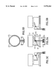
- FIG. 2A is a front view showing the focusing and defocusing mechanism according to the preferred embodiment of the present invention.
- FIG. 2B is a side view showing the outer lens barrel with a guide pin according to the preferred embodiment of the present invention.
- FIG. 2C is a side view showing the structure of cam barrel having a slot of multiple slopes according to the preferred embodiment of the present invention.
- FIG. 2D is a schematic diagram showing the function of the limited slide according to the preferred embodiment of the present invention.
- FIG. 3A is a front view showing the focusing and defocusing mechanism according to the preferred embodiment of the present invention.
- FIG. 3B is a side view showing the focusing and defocusing mechanism according to the preferred embodiment of the present invention.
- FIG. 3C is another side view showing the focusing and defocusing mechanism according to the preferred embodiment of the present invention.
- FIG. 3D is a top view showing the focusing and defocusing mechanism according to the preferred embodiment of the present invention.
- FIG. 4 is an exploded view showing each component of the focusing and defocusing mechanism according to the preferred embodiment of the present invention.
- the present invention provides a cam barrel with a slot of multiple slopes for determining the axial movement of a lens barrel while performing focusing and defocusing.
- the invention uses a guide pin fixed onto the outer wall of a cylindrical lens mount for guiding the lens barrel along the slot of multiple slopes without using any spring.
- the guide pin is an elastic pin with a single groove. It is used to replace the function of a convention spring. The simplicity of the entire focusing and defocusing mechanism intends to save the time and cost in assemble and maintenance.
- FIG. 2A illustrates the focusing and defocusing mechanism according to the preferred embodiment of the present invention.
- the mechanism comprises an outer lens barrel 21 having a guide pin 23 fixed on the outer wall of its cylindrical lens mount, a cam barrel 22 having a slot of multiple slopes 25, a focusing lever 24, a control button 26, and a limited slide for focusing 27.
- the guide pin 23 is attached onto the outer wall of cylindrical lens mount of the outer lens barrel 21.
- the guide pin 23 is an elastic pin with a single groove. The elasticity of the guide pin 23 helps to reduce vibrations of the outer lens barrel 21 while being shifted along the slot of multiple slopes.
- the outer lens barrel 21 is movable and adapted to rotate into the cam barrel 22. While the outer lens barrel 21 is rotating into the cam barrel 22, the guide pin 23 is slided into the slot of multiple slopes 25.
- the cam barrel 22 and the slot of multiple slopes 25 are illustrated in FIG. 2C.
- the various slopes of the slot 25 define the axial movement of the outer lens barrel 21 for focusing and defocusing. For instance, when the guide pin 23 is shifted to locate at slopes 251 and 252, the outer lens barrel 21 can be set to focus. In contrast, while the guide pin 23 is shifted to locate at slope 253, the outer lens barrel 21 is set to defocus.
- the guide pin 23 is controlled by controlling means which consists of a focusing lever 24, a control button 26 and a limited slide for focusing 27.
- the control lever 24 can hold the control pin firmly and shift it back and forth along the slot of multiple slopes 25.
- the focusing lever 24 is further controlled by an external control button 26 which can be manually operated for easy to focus and defocus while taking pictures.
- the shift distance of the guide pin 23 on the slot of multiple slopes 25 is controlled by a limited slide for focusing 27.
- the function of the limited slide for focusing 27 is schematically illustrated in FIG. 2D. It is known that focusing and defocusing depend on the movement of the outer lens barrel 21 along the optical axis of the camera lens barrel. For instance, to capture an object located at a far distance, the position of the outer lens barrel 21 on the slot of multiple slopes 25 is set to II'. And for an object located at a near distance, the position of the outer lens barrel 21 on the slot of multiple slopes 25 is set to II II'. If a user finds that the object is very close, he/she will manually operate the limited slide for focusing 27 to position X. At this time, the outer lens barrel 21 will shift from position 0 to position a+b.
- the axial movement of the outer lens barrel 21 is moving forward a+b distance.
- a user finds that the object is very far away, he/she will manually operate the limited slide for focusing 27 to position Y.
- the outer lens barrel 21 will then shift from position a to position a+b+c. That is, the axial movement of the outer lens barrel 21 is further shifted forward a+b distance with respect to the optical axis of the lens barrel. Consequently, a user can always focus or defocus an object by simply pushing the control button 26 back and forth which will cause the outer lens barrel 21 to shift back and forth with respect to the optical axis of the camera lens barrel.
- FIG. 3A illustrates the front view of the invention.
- FIG. 3B and 3C illustrate its side views while FIG. 3D its top view. From these views, we can see better that the outer lens barrel 31 is moveable and its cylindrical lens mount can fit into the cam barrel 32. While the cylindrical lens mount of the outer lens barrel is sliding into the cam barrel 32, the guide pin 34 rotates into the slot of multiple slopes 33.
- the guide pin 34 is controlled by controlling means which consists of a focusing lever 35, a control button 36 and a limited slide for focusing 37.
- the outer lens barrel 41 contains a lens 41 a and a cylindrical lens mount 41b.
- a guide pin 42 is attached on the outer wall of the cylindrical lens mount 41b.
- the cam barrel 43 contains a slot of multiple slopes 44 and a retaining plate 48.
- the rods 49a and 49b are fixed at the retaining plate 48 attached to the rear end of the compartment of an inner lens barrel (not shown).
- the outer lens barrel 41 is sized to fit into the cam barrel 43 for sliding moveable along the optical axis of the camera lens barrels.
- the shape of the focusing lever 45 is like a fork for holding the guide pin 42 firmly. The focusing lever 45 can be shifted horizontally with respect to the cam barrel 43.
- a hole 50 for fixing to a control button 47 At the other end of the focusing lever 45, there is a hole 50 for fixing to a control button 47.
- the control button 47 is engaged to a limited slide for focusing 46.
- the limited slide for focusing 46 can be shifted in a horizontal direction with respect to the cam barrel 43.
- the invention can perform focusing and defocusing without using the conventional cam ring and spring structure. More importantly, the lens structure can be simplified in a great scale. Consequently, the time and cost in manufacture and assemble can be saved.
Landscapes
- Physics & Mathematics (AREA)
- General Physics & Mathematics (AREA)
- Optics & Photonics (AREA)
- Lens Barrels (AREA)
Abstract
Description
Claims (8)
Priority Applications (2)
| Application Number | Priority Date | Filing Date | Title |
|---|---|---|---|
| US09/040,227 US5970262A (en) | 1998-03-13 | 1998-03-13 | Spring-free type focusing and defocusing mechanism for a digital camera |
| GB9805566A GB2335503A (en) | 1998-03-13 | 1998-03-16 | A spring-free type focussing and defocusing mechanism for a digital camera |
Applications Claiming Priority (2)
| Application Number | Priority Date | Filing Date | Title |
|---|---|---|---|
| US09/040,227 US5970262A (en) | 1998-03-13 | 1998-03-13 | Spring-free type focusing and defocusing mechanism for a digital camera |
| GB9805566A GB2335503A (en) | 1998-03-13 | 1998-03-16 | A spring-free type focussing and defocusing mechanism for a digital camera |
Publications (1)
| Publication Number | Publication Date |
|---|---|
| US5970262A true US5970262A (en) | 1999-10-19 |
Family
ID=26313289
Family Applications (1)
| Application Number | Title | Priority Date | Filing Date |
|---|---|---|---|
| US09/040,227 Expired - Lifetime US5970262A (en) | 1998-03-13 | 1998-03-13 | Spring-free type focusing and defocusing mechanism for a digital camera |
Country Status (2)
| Country | Link |
|---|---|
| US (1) | US5970262A (en) |
| GB (1) | GB2335503A (en) |
Cited By (4)
| Publication number | Priority date | Publication date | Assignee | Title |
|---|---|---|---|---|
| US6724428B1 (en) * | 1999-08-31 | 2004-04-20 | Nucam Corporation | Shutter and lens apparatus of a digital camera with a stepless focusing function |
| US20050220453A1 (en) * | 2004-04-06 | 2005-10-06 | Smk Corporation | Camera module |
| US20050286352A1 (en) * | 2004-06-25 | 2005-12-29 | Toshiharu Inui | Lens driving unit |
| US20080031612A1 (en) * | 2006-08-04 | 2008-02-07 | Hon Hai Precision Industry Co., Ltd. | Mobile communication device |
Citations (4)
| Publication number | Priority date | Publication date | Assignee | Title |
|---|---|---|---|---|
| US17937A (en) * | 1857-08-04 | William s | ||
| USRE17937E (en) | 1931-01-20 | stewart | ||
| US4585313A (en) * | 1982-12-14 | 1986-04-29 | West Electric Company Ltd. | Lens drive device and optical lens assembly utilizing the same |
| US5113261A (en) * | 1989-07-11 | 1992-05-12 | Asahi Kogaku Kogyo Kabushiki Kaisha | Lens driving apparatus using cam plate |
-
1998
- 1998-03-13 US US09/040,227 patent/US5970262A/en not_active Expired - Lifetime
- 1998-03-16 GB GB9805566A patent/GB2335503A/en not_active Withdrawn
Patent Citations (4)
| Publication number | Priority date | Publication date | Assignee | Title |
|---|---|---|---|---|
| US17937A (en) * | 1857-08-04 | William s | ||
| USRE17937E (en) | 1931-01-20 | stewart | ||
| US4585313A (en) * | 1982-12-14 | 1986-04-29 | West Electric Company Ltd. | Lens drive device and optical lens assembly utilizing the same |
| US5113261A (en) * | 1989-07-11 | 1992-05-12 | Asahi Kogaku Kogyo Kabushiki Kaisha | Lens driving apparatus using cam plate |
Cited By (6)
| Publication number | Priority date | Publication date | Assignee | Title |
|---|---|---|---|---|
| US6724428B1 (en) * | 1999-08-31 | 2004-04-20 | Nucam Corporation | Shutter and lens apparatus of a digital camera with a stepless focusing function |
| US20050220453A1 (en) * | 2004-04-06 | 2005-10-06 | Smk Corporation | Camera module |
| US7127162B2 (en) * | 2004-04-06 | 2006-10-24 | Smk Corporation | Camera module |
| US20050286352A1 (en) * | 2004-06-25 | 2005-12-29 | Toshiharu Inui | Lens driving unit |
| US20080031612A1 (en) * | 2006-08-04 | 2008-02-07 | Hon Hai Precision Industry Co., Ltd. | Mobile communication device |
| US7577352B2 (en) * | 2006-08-04 | 2009-08-18 | Hon Hai Precision Industry Co., Ltd. | Mobile communication device |
Also Published As
| Publication number | Publication date |
|---|---|
| GB2335503A (en) | 1999-09-22 |
| GB9805566D0 (en) | 1998-05-13 |
Similar Documents
| Publication | Publication Date | Title |
|---|---|---|
| US5037187A (en) | Zoom lens mount assembly | |
| US5937215A (en) | Camera having a zoom lens | |
| US5376983A (en) | Lens barrel | |
| JP3650599B2 (en) | Zoom lens barrel | |
| US8757903B2 (en) | Diaphragm device of lens | |
| JP5334311B2 (en) | Lens device | |
| JPS61128217A (en) | Automatic focusing camera with variable focus | |
| US8559807B2 (en) | Camera system and lens barrel | |
| US5191471A (en) | Adjusting mechanism of binoculars | |
| US5392160A (en) | Lens barrel having a flare diaphragm mechanism | |
| US5970262A (en) | Spring-free type focusing and defocusing mechanism for a digital camera | |
| US4352546A (en) | Camera selectively settable to either standard photographic mode or supertelephotographic mode | |
| US4264175A (en) | Focusing device in camera equipped with both standard and telephoto lenses | |
| JP5479034B2 (en) | Lens device | |
| JP2020067575A (en) | Lens barrel | |
| US6408139B1 (en) | Zoom finder | |
| JP5090270B2 (en) | Support structure for the light amount adjustment unit of the lens barrel | |
| JP2006072070A (en) | Lens barrel | |
| JPH04229845A (en) | Lens barrel | |
| JPS5841522Y2 (en) | focus adjustment device | |
| JP2000231141A (en) | Variable power finder device | |
| CN218298632U (en) | Optical lens with switchable field of view | |
| US20250020982A1 (en) | Camera and switch | |
| JPH0634863A (en) | Photographing lens barrel | |
| JP2569529B2 (en) | Close-up photography device |
Legal Events
| Date | Code | Title | Description |
|---|---|---|---|
| AS | Assignment |
Owner name: UMAX DATA SYSTEMS INC., TAIWAN Free format text: ASSIGNMENT OF ASSIGNORS INTEREST;ASSIGNORS:TSENG, KOU-LUNG;HWANG, WEI-HSIN;CHEN, CHAO-SOON;AND OTHERS;REEL/FRAME:009102/0808 Effective date: 19980302 |
|
| STCF | Information on status: patent grant |
Free format text: PATENTED CASE |
|
| FPAY | Fee payment |
Year of fee payment: 4 |
|
| AS | Assignment |
Owner name: VEUTRON CORPORATION, TAIWAN Free format text: CHANGE OF NAME;ASSIGNOR:UMAX DATA SYSTEMS INC.;REEL/FRAME:016800/0203 Effective date: 20021029 |
|
| AS | Assignment |
Owner name: TRANSPACIFIC IP, LTD.,TAIWAN Free format text: ASSIGNMENT OF ASSIGNORS INTEREST;ASSIGNOR:VEUTRON CORPORATION;REEL/FRAME:017564/0747 Effective date: 20050706 Owner name: TRANSPACIFIC IP, LTD., TAIWAN Free format text: ASSIGNMENT OF ASSIGNORS INTEREST;ASSIGNOR:VEUTRON CORPORATION;REEL/FRAME:017564/0747 Effective date: 20050706 |
|
| FPAY | Fee payment |
Year of fee payment: 8 |
|
| AS | Assignment |
Owner name: TRANSPACIFIC SYSTEMS, LLC, DELAWARE Free format text: ASSIGNMENT OF ASSIGNORS INTEREST;ASSIGNOR:TRANSPACIFIC IP LTD.;REEL/FRAME:023107/0267 Effective date: 20090618 Owner name: TRANSPACIFIC SYSTEMS, LLC,DELAWARE Free format text: ASSIGNMENT OF ASSIGNORS INTEREST;ASSIGNOR:TRANSPACIFIC IP LTD.;REEL/FRAME:023107/0267 Effective date: 20090618 |
|
| FPAY | Fee payment |
Year of fee payment: 12 |
|
| AS | Assignment |
Owner name: TITUSVILLE CANAVERAL LLC, DELAWARE Free format text: MERGER;ASSIGNOR:TRANSPACIFIC SYSTEMS, LLC;REEL/FRAME:030628/0681 Effective date: 20130213 |
|
| AS | Assignment |
Owner name: INTELLECTUAL VENTURES I LLC, DELAWARE Free format text: MERGER;ASSIGNOR:TITUSVILLE CANAVERAL LLC;REEL/FRAME:030639/0330 Effective date: 20130214 |
|
| AS | Assignment |
Owner name: HANGER SOLUTIONS, LLC, GEORGIA Free format text: ASSIGNMENT OF ASSIGNORS INTEREST;ASSIGNOR:INTELLECTUAL VENTURES ASSETS 161 LLC;REEL/FRAME:052159/0509 Effective date: 20191206 |
|
| AS | Assignment |
Owner name: INTELLECTUAL VENTURES ASSETS 161 LLC, DELAWARE Free format text: ASSIGNMENT OF ASSIGNORS INTEREST;ASSIGNOR:INTELLECTUAL VENTURES I LLC;REEL/FRAME:051945/0001 Effective date: 20191126 |