US5960953A - Tray for supporting a plurality of nail packs - Google Patents

Tray for supporting a plurality of nail packs Download PDF

Info

Publication number
US5960953A
US5960953A US09/055,776 US5577698A US5960953A US 5960953 A US5960953 A US 5960953A US 5577698 A US5577698 A US 5577698A US 5960953 A US5960953 A US 5960953A
Authority
US
United States
Prior art keywords
nail
tray
tray body
supporting surface
pack
Prior art date
Legal status (The legal status is an assumption and is not a legal conclusion. Google has not performed a legal analysis and makes no representation as to the accuracy of the status listed.)
Expired - Fee Related
Application number
US09/055,776
Inventor
Jeffrey J. Gratz
Current Assignee (The listed assignees may be inaccurate. Google has not performed a legal analysis and makes no representation or warranty as to the accuracy of the list.)
Fibreform Containers Inc
Original Assignee
Fibreform Containers Inc
Priority date (The priority date is an assumption and is not a legal conclusion. Google has not performed a legal analysis and makes no representation as to the accuracy of the date listed.)
Filing date
Publication date
Application filed by Fibreform Containers Inc filed Critical Fibreform Containers Inc
Priority to US09/055,776 priority Critical patent/US5960953A/en
Priority to CA002267685A priority patent/CA2267685A1/en
Assigned to FIBREFORM CONTAINERS, INC. reassignment FIBREFORM CONTAINERS, INC. ASSIGNMENT OF ASSIGNORS INTEREST (SEE DOCUMENT FOR DETAILS). Assignors: GRATZ, JEFFREY J.
Application granted granted Critical
Publication of US5960953A publication Critical patent/US5960953A/en
Anticipated expiration legal-status Critical
Expired - Fee Related legal-status Critical Current

Links

Images

Classifications

    • BPERFORMING OPERATIONS; TRANSPORTING
    • B65CONVEYING; PACKING; STORING; HANDLING THIN OR FILAMENTARY MATERIAL
    • B65DCONTAINERS FOR STORAGE OR TRANSPORT OF ARTICLES OR MATERIALS, e.g. BAGS, BARRELS, BOTTLES, BOXES, CANS, CARTONS, CRATES, DRUMS, JARS, TANKS, HOPPERS, FORWARDING CONTAINERS; ACCESSORIES, CLOSURES, OR FITTINGS THEREFOR; PACKAGING ELEMENTS; PACKAGES
    • B65D71/00Bundles of articles held together by packaging elements for convenience of storage or transport, e.g. portable segregating carrier for plural receptacles such as beer cans or pop bottles; Bales of material
    • B65D71/70Trays provided with projections or recesses in order to assemble multiple articles, e.g. intermediate elements for stacking

Definitions

  • This invention relates to packaging, and in particular, to a tray for use in the packaging, transport and/or storage of nail packs.
  • a nail gun In order to expedite the nailing process in construction, a nail gun is often used to replace the conventional hammer.
  • a nail gun utilizes pneumatic or hydraulic pressure to drive a nail into a predetermined location. Since nail guns have the ability to perform this process very quickly, nails must be continuously fed into the nail gun.
  • Nail packs have been designed to facilitate the rapid feeding of nails into the nail gun.
  • the nail pack consists of a plurality of nails interconnected linearly by one or more wires to form a "string" of nails.
  • the attached nails are rolled into a donut-shaped pack. These nail packs are then packaged for shipment and/or storage.
  • trays have been used to support the nail packs during transport and/or storage.
  • these prior art nail trays are constructed from materials such as molded fiber, expanded polystyrene, or the like.
  • prior art trays for nail packs lack sufficient strength to support the nail packs during transport and storage.
  • nail packs are typically deposited on the nail trays by a nail pack depositing mechanism as the nail trays are conveyed along a conveyor belt. It is highly desirable to increase the rate at which the nail packs are deposited on the tray. This, in turn, requires a simple and inexpensive means for detecting the position of a nail tray relative to the nail pack depositing mechanism.
  • FIG. 1 is an isometric view of a nail tray in accordance with the present invention
  • FIG. 2 is a side elevational view of the nail tray of FIG. 1;
  • FIG. 3 is an enlarged, cross-sectional view taken along line 3--3 of FIG. 1 showing a portion of a stack of trays holding a nail pack therebetween;
  • FIG. 4a is a top plan view of the nail tray of the present invention in a first position prior to the depositing of nail packs onto the nail tray;
  • FIG. 4b is a cross-sectional view of FIG. 4a showing the nail tray of the present invention in the first position
  • FIG. 5a is a top plan view of the nail tray of the present invention in a second, nail pack depositing position
  • FIG. 5b is a cross-sectional view of FIG. 5a showing the nail tray of the present invention in the second position;
  • FIG. 6a is a top plan view showing the nail tray of the present invention in the second position after a first row of nail packs have been deposited thereon;
  • FIG. 6b is a cross-sectional view of FIG. 6a showing the nail tray of the present invention in the second position after a first row of nail packs have been deposited thereon;
  • FIG. 7a is a top plan view showing the nail tray of the present invention in a third position prior to depositing a second row of nail packs thereon;
  • FIG. 7b is a cross-sectional view of FIG. 7a showing the nail tray of the present invention in the third position.
  • a nail tray in accordance with the present invention is generally designated by the reference numeral 10. It is contemplated that nail tray 10 be formed from a molded fibrous or plastic material. However, it is contemplated that the nail tray of the present invention be formed from other materials such as paper, corrugated, sheet metal or the like.
  • Nail tray 10 includes a generally planar support member 12 having an upwardly facing surface 14 and an opposite, downwardly facing surface 16. As best seen in FIGS. 1 and 5a-7b, nail tray 10 is generally rectangular in shape. However, it is contemplated that nail tray 10 be formed of any configuration.
  • Nail tray 10 includes an outer periphery 18 defined by first and second parallel side edges 20 and 22, respectively, and first and second ends 24 and (not shown) perpendicular to side edges 20 and 22. Each side edge 20 and 22 is interconnected to a corresponding end 24 and (not shown) by a chamfered corner 26. Each chamfered corner 26 facilitates the insertion of nail tray 10 into a packaging container such as a corrugated box or the like by removing a portion of the nail tray 10, i.e. the corner, which may hang up against the interior surface of the packaging container upon insertion of the nail tray 10 therein.
  • a packaging container such as a corrugated box or the like
  • a stiffening wall 28 projects vertically from the outer periphery 18 of nail tray 10.
  • Stiffening wall 28 includes first and second parallel side portions 30 and 32 and first and second end portions 34 and 36, respectively, transverse to side portions 30 and 32. Corner portions 38 of stiffening wall 28 project vertically from each chamfered corner 26 and interconnect ends of side portions 30 and 32 with corresponding ends of end portions 34 and 36.
  • a horizontal, generally planar lip 35 extends laterally from the upper end of stiffening wall 28.
  • Planar lip 35 includes side portions 37 and 39 which extend laterally from the upper end of corresponding side portions 30 and 32, respectively, of stiffening wall 28.
  • end portions 41 and 43 of planar lip 35 extend from the upper end of corresponding end portions 34 and 36, respectively, of stiffening wall 28.
  • Corner portions 45 of planar lip 35 extend horizontally from corresponding corner portions 38 of stiffening wall 28 and interconnect side portions 37 and 39 of planar lip 35 to corresponding end portions 41 and 43 of planar lip 35.
  • Planar lip 35 is defined by a generally planar upper surface 35a, and an opposite, downwardly facing surface 35b. Upper surface 35a and downwardly facing surface 35b of planar lip 35 are interconnected by a generally vertical, outer edge 35c. Planer lip 35 and stiffening wall 28 provide strength and rigidity to nail tray 10.
  • Nail tray 10 further includes a plurality of nail pack retaining projections 40 integrally molded with and disposed in uniformly spaced relation over the nail tray 10. As shown in the drawings, nail pack retaining projections 40 are arranged in a plurality of rows 42a-c and a plurality of columns 44a-d. However, it is contemplated as being within the scope of the present invention to arrange retaining projections 40 in various configurations over nail tray 10, and it is further contemplated that the number of rows and columns of retaining projections 40 disposed on nail tray 10 be varied to a desired number.
  • each nail pack retaining projection 40 is generally convex in shape and includes an upper nail engaging surface 48 which projects from the upwardly facing surface 14 of nail tray 10.
  • a generally cylindrical retaining element 50 projects vertically from the apex of nail engaging surface 48.
  • Nail retaining element 50 is defined by a generally cylindrical outer wall 52 which extends vertically from nail engaging surface 48.
  • a nail retaining element 50 further includes a horizontal, upper surface 54 which is perpendicular to outer wall 52 of nail retaining element 50.
  • the diameter of nail retaining element 50 is generally equal to the diameter of opening 55 formed in the center of nail pack 56, FIG. 3.
  • Nail tray 10 further includes a plurality of finger hole structures 60a-f arranged in rows 62a and 62b and columns 64a-c.
  • Each finger hole structure 60a-f is generally tubular and includes an outer surface 66 having a generally rectangular cross section. Outer surface 66 of each finger hole structure 60a-f is defined by generally vertical side wall portions 68a-d. Side wall portion 68a and 68c of each finger hole structure 60a-f are generally planer and lie in parallel planes. Similarly, side wall portions 68b and 68d of each finger hole structure 60a-f are planer and lie in parallel planes. Side wall portions 68a and 68c are perpendicular to side wall portions 68b and 68d of each finger hole structure 60a-f.
  • Each finger hole structure 60a-f further includes an inner surface 70 which defines a generally conical passageway 72 which terminates at a generally circular opening 74 in the bottom surface 16 of nail tray 10.
  • Inner surface 70 is spaced from outer surface 66 so as to define rigid wall 77 therebetween.
  • a user may extend one or more fingers through passageway 72 in a corresponding finger structure 60a-f so as to allow the user to grasp a corresponding nail tray 10 therewith.
  • Rigid wall 77 provides sufficient strength and stability so as to allow a user to lift nail tray 10 by finger holes structures 60a-f above a supporting surface.
  • Nail tray 10 further includes a plurality of sensor structures 80 spaced about the outer periphery of nail tray 10.
  • Each sensor structure 80 includes first and second vertical walls 84 and 86, respectively extending from the upper surface 14 of nail tray 10.
  • Vertical walls 84 and 86 are perpendicular to each other and diverge from a corner 88.
  • Each vertical wall 84 and 86 lies in a plane parallel to either side wall portions 68a and 68c or side wall portions 68b and 68d of each finger hole structure 60a-f.
  • Each sensor structure 80 further includes a third wall 90 which extends vertically from the outer periphery 18 of nail tray 10 and between vertical walls 84 and 86 of sensor structure 80.
  • Vertical walls 84, 86 and 90 are interconnected by a horizontal upper wall 92.
  • Each nail pack retaining projection 40 partially defines a pocket for receiving a nail pack.
  • a pocket 91 is shown in phantom in FIG. 1.
  • Pocket 91 is defined by vertical walls 84 and 86 of corresponding sensor structures 80a and 80b, as well as by side wall portions 68c and 68a of finger hole structures 60a and 60b, respectively.
  • each concave depression 94 is formed on nail tray 10 opposite convex surface 48 of each nail pack retaining member 40, and is dimensioned to receive an upper portion of corresponding nail pack 56 therein, FIG. 3.
  • nail tray 10 is positioned on a conveyor 100.
  • conveyor 100 moves from left to right in FIGS. 4a-4b.
  • a nail pack deposit assembly is provided and includes a signal generator 102 and a receiver 104 positioned on opposite sides 106 and 108, respectively, of conveyor 100.
  • Signal generator 102 and receiver 104 are in axial alignment at a level between the upper surface of stiffening wall 28 and horizontal upper wall 92 of each sensor structure 80.
  • Nail pack depositing assembly further includes a nail pack depositing structure 110 which deposits nail packs 56 on corresponding nail pack retaining members 40 in response to a signal from receiver 104.
  • signal generator 102 transmits a signal therefrom which is received by receiver 104.
  • a nail tray 10 is placed on conveyor 100.
  • the signal generated by signal generator 102 engages vertical wall 84 of sensor structure 80 so as to prevent receiver 104 from receiving the signal and to initialize the depositing of nail packs 56 on nail tray 10.
  • receiver 104 As nail tray 10 continues along conveyor 100, the signal generated by signal generator 102 is received by receiver 104, FIG. 5a. Upon receiving signal from signal generator 102, receiver 104 instructs nail pack depositing structure 110 to deposit a nail pack 56 on each nail pack retaining member 40 in column 44a of nail tray 10, FIG. 5b. Each nail pack 56 is deposited on a corresponding nail pack retaining member 40 such that nail retaining element 50 is received within a corresponding opening 55 formed in the center of nail pack 56, and such that the tips 103 of each nail 105 of nail pack 56 engage the upper nail engaging surface 48 on the upwardly facing surface 14 of support member 12.
  • receiver 104 With nail packs 56 deposited on each nail pack retaining member 40 in column 44a of nail tray 10, receiver 104 is blocked from receiving the signal generated by signal generator 102, FIG. 6a. As a result, receiver 104 instructs conveyor 100 to conveying nail tray 10, from left to right in FIG. 6b, until such time that receiver 104 once again receives the signal from signal generator 102, FIG. 7a. Receiver 104 receives the signal from signal generator 102, nail pack depositing structure 110 is in alignment with and overlaps corresponding nail pack retaining members 40 in a column 44b of nail tray 10, FIG. 7b.
  • receiver 104 Upon receiving the signal from signal generator 102, receiver 104 instructs nail pack depositing structure 110 to deposit a nail pack 56 on each hail pack retaining member 40 in column 44b of nail tray 10, as heretofore described. The process is continued until such time as a nail pack 56 is deposited on each nail pack retaining member 40 of nail tray 10.
  • a plurality of nail trays 10 may be positioned on conveyor 100 in order to deposit nail packs 56 on each of the nail trays 10. Thereafter, the nail trays 10 may be stacked upon each other, FIG. 3, in order for storage or shipment. With nail trays 10 stacked upon each other, FIG. 3, the heads 107 of each nail 105 of nail pack 56 are receivable within a corresponding concave depression 94 in downwardly facing surface 16 of support member 12.

Landscapes

  • Engineering & Computer Science (AREA)
  • Mechanical Engineering (AREA)
  • Packaging Of Annular Or Rod-Shaped Articles, Wearing Apparel, Cassettes, Or The Like (AREA)

Abstract

A tray for supporting a plurality of nail packs is provided. The tray includes a generally rectangular planar tray body having a nail supporting surface and an outer periphery. A stiffening wall projects vertically from the outer periphery of the tray body and terminates at an upper end. A generally planar lip extends laterally from the upper end of the stiffening wall. A sensing structure extends vertically from the nail supporting surface of the tray body beyond the upper end of the stiffening wall.

Description

BACKGROUND AND SUMMARY OF THE INVENTION
This invention relates to packaging, and in particular, to a tray for use in the packaging, transport and/or storage of nail packs.
In order to expedite the nailing process in construction, a nail gun is often used to replace the conventional hammer. A nail gun utilizes pneumatic or hydraulic pressure to drive a nail into a predetermined location. Since nail guns have the ability to perform this process very quickly, nails must be continuously fed into the nail gun.
Nail packs have been designed to facilitate the rapid feeding of nails into the nail gun. The nail pack consists of a plurality of nails interconnected linearly by one or more wires to form a "string" of nails. In order to transport the "string", the attached nails are rolled into a donut-shaped pack. These nail packs are then packaged for shipment and/or storage.
Heretofore, trays have been used to support the nail packs during transport and/or storage. Typically, these prior art nail trays are constructed from materials such as molded fiber, expanded polystyrene, or the like. However, it has been found that prior art trays for nail packs lack sufficient strength to support the nail packs during transport and storage.
Further, nail packs are typically deposited on the nail trays by a nail pack depositing mechanism as the nail trays are conveyed along a conveyor belt. It is highly desirable to increase the rate at which the nail packs are deposited on the tray. This, in turn, requires a simple and inexpensive means for detecting the position of a nail tray relative to the nail pack depositing mechanism.
Therefore, it is a primary object and feature of the present invention to provide a nail tray for the transport and/or storage of nail packs which is simple and inexpensive to manufacture.
It is a still object and feature of the present invention to provide a nail tray for the transport and/or storage of nail packs which provide sufficient support for the nail packs during transport and/or storage.
It is a still further object and feature of the present invention to provide a nail tray for the transport and/or storage of nail packs which incorporates a simple inexpensive mechanism for facilitating the depositing of the nail packs thereon.
Various other features, objects and advantages of the invention will be made apparent from the following description taken together with the drawings.
BRIEF DESCRIPTION OF THE DRAWINGS
The drawings furnished herewith illustrate a preferred construction of the present invention in which the above advantages and features are clearly disclosed as well as others which will be readily understood from the following description of the illustrated embodiment.
In the drawings:
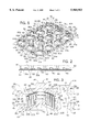
FIG. 1 is an isometric view of a nail tray in accordance with the present invention;
FIG. 2 is a side elevational view of the nail tray of FIG. 1;
FIG. 3 is an enlarged, cross-sectional view taken along line 3--3 of FIG. 1 showing a portion of a stack of trays holding a nail pack therebetween;
FIG. 4a is a top plan view of the nail tray of the present invention in a first position prior to the depositing of nail packs onto the nail tray;
FIG. 4b is a cross-sectional view of FIG. 4a showing the nail tray of the present invention in the first position;
FIG. 5a is a top plan view of the nail tray of the present invention in a second, nail pack depositing position;
FIG. 5b is a cross-sectional view of FIG. 5a showing the nail tray of the present invention in the second position;
FIG. 6a is a top plan view showing the nail tray of the present invention in the second position after a first row of nail packs have been deposited thereon;
FIG. 6b is a cross-sectional view of FIG. 6a showing the nail tray of the present invention in the second position after a first row of nail packs have been deposited thereon;
FIG. 7a is a top plan view showing the nail tray of the present invention in a third position prior to depositing a second row of nail packs thereon; and
FIG. 7b is a cross-sectional view of FIG. 7a showing the nail tray of the present invention in the third position.
DETAILED DESCRIPTION OF THE INVENTION
Referring to FIG. 1, a nail tray in accordance with the present invention is generally designated by the reference numeral 10. It is contemplated that nail tray 10 be formed from a molded fibrous or plastic material. However, it is contemplated that the nail tray of the present invention be formed from other materials such as paper, corrugated, sheet metal or the like.
Nail tray 10 includes a generally planar support member 12 having an upwardly facing surface 14 and an opposite, downwardly facing surface 16. As best seen in FIGS. 1 and 5a-7b, nail tray 10 is generally rectangular in shape. However, it is contemplated that nail tray 10 be formed of any configuration.
Nail tray 10 includes an outer periphery 18 defined by first and second parallel side edges 20 and 22, respectively, and first and second ends 24 and (not shown) perpendicular to side edges 20 and 22. Each side edge 20 and 22 is interconnected to a corresponding end 24 and (not shown) by a chamfered corner 26. Each chamfered corner 26 facilitates the insertion of nail tray 10 into a packaging container such as a corrugated box or the like by removing a portion of the nail tray 10, i.e. the corner, which may hang up against the interior surface of the packaging container upon insertion of the nail tray 10 therein.
A stiffening wall 28 projects vertically from the outer periphery 18 of nail tray 10. Stiffening wall 28 includes first and second parallel side portions 30 and 32 and first and second end portions 34 and 36, respectively, transverse to side portions 30 and 32. Corner portions 38 of stiffening wall 28 project vertically from each chamfered corner 26 and interconnect ends of side portions 30 and 32 with corresponding ends of end portions 34 and 36.
A horizontal, generally planar lip 35 extends laterally from the upper end of stiffening wall 28. Planar lip 35 includes side portions 37 and 39 which extend laterally from the upper end of corresponding side portions 30 and 32, respectively, of stiffening wall 28. Similarly, end portions 41 and 43 of planar lip 35 extend from the upper end of corresponding end portions 34 and 36, respectively, of stiffening wall 28. Corner portions 45 of planar lip 35 extend horizontally from corresponding corner portions 38 of stiffening wall 28 and interconnect side portions 37 and 39 of planar lip 35 to corresponding end portions 41 and 43 of planar lip 35.
Planar lip 35 is defined by a generally planar upper surface 35a, and an opposite, downwardly facing surface 35b. Upper surface 35a and downwardly facing surface 35b of planar lip 35 are interconnected by a generally vertical, outer edge 35c. Planer lip 35 and stiffening wall 28 provide strength and rigidity to nail tray 10.
Nail tray 10 further includes a plurality of nail pack retaining projections 40 integrally molded with and disposed in uniformly spaced relation over the nail tray 10. As shown in the drawings, nail pack retaining projections 40 are arranged in a plurality of rows 42a-c and a plurality of columns 44a-d. However, it is contemplated as being within the scope of the present invention to arrange retaining projections 40 in various configurations over nail tray 10, and it is further contemplated that the number of rows and columns of retaining projections 40 disposed on nail tray 10 be varied to a desired number.
As best seen in FIG. 3, each nail pack retaining projection 40 is generally convex in shape and includes an upper nail engaging surface 48 which projects from the upwardly facing surface 14 of nail tray 10. A generally cylindrical retaining element 50 projects vertically from the apex of nail engaging surface 48.
Nail retaining element 50 is defined by a generally cylindrical outer wall 52 which extends vertically from nail engaging surface 48. A nail retaining element 50 further includes a horizontal, upper surface 54 which is perpendicular to outer wall 52 of nail retaining element 50. The diameter of nail retaining element 50 is generally equal to the diameter of opening 55 formed in the center of nail pack 56, FIG. 3.
Nail tray 10 further includes a plurality of finger hole structures 60a-f arranged in rows 62a and 62b and columns 64a-c. Each finger hole structure 60a-f is generally tubular and includes an outer surface 66 having a generally rectangular cross section. Outer surface 66 of each finger hole structure 60a-f is defined by generally vertical side wall portions 68a-d. Side wall portion 68a and 68c of each finger hole structure 60a-f are generally planer and lie in parallel planes. Similarly, side wall portions 68b and 68d of each finger hole structure 60a-f are planer and lie in parallel planes. Side wall portions 68a and 68c are perpendicular to side wall portions 68b and 68d of each finger hole structure 60a-f.
Each finger hole structure 60a-f further includes an inner surface 70 which defines a generally conical passageway 72 which terminates at a generally circular opening 74 in the bottom surface 16 of nail tray 10. Inner surface 70 is spaced from outer surface 66 so as to define rigid wall 77 therebetween. In operation, a user may extend one or more fingers through passageway 72 in a corresponding finger structure 60a-f so as to allow the user to grasp a corresponding nail tray 10 therewith. Rigid wall 77 provides sufficient strength and stability so as to allow a user to lift nail tray 10 by finger holes structures 60a-f above a supporting surface.
Nail tray 10 further includes a plurality of sensor structures 80 spaced about the outer periphery of nail tray 10. Each sensor structure 80 includes first and second vertical walls 84 and 86, respectively extending from the upper surface 14 of nail tray 10. Vertical walls 84 and 86 are perpendicular to each other and diverge from a corner 88. Each vertical wall 84 and 86 lies in a plane parallel to either side wall portions 68a and 68c or side wall portions 68b and 68d of each finger hole structure 60a-f.
Each sensor structure 80 further includes a third wall 90 which extends vertically from the outer periphery 18 of nail tray 10 and between vertical walls 84 and 86 of sensor structure 80. Vertical walls 84, 86 and 90 are interconnected by a horizontal upper wall 92.
Each nail pack retaining projection 40 partially defines a pocket for receiving a nail pack. By way of example, a pocket 91 is shown in phantom in FIG. 1. Pocket 91 is defined by vertical walls 84 and 86 of corresponding sensor structures 80a and 80b, as well as by side wall portions 68c and 68a of finger hole structures 60a and 60b, respectively. Vertical walls 84 and 86 of sensor structures 80a and 80b, respectively, and side wall portions 68b and 68c of finger hole structures 60b and 60a, respectively, prevent the lateral movement of a nail pack 56 within pocket 91 on nail tray 10.
In order to facilitate the stacking of nail trays 10 on each other, a plurality of concave depressions 94 are formed in the downwardly facing surface 16 of nail tray 10. Each concave depression 94 is formed on nail tray 10 opposite convex surface 48 of each nail pack retaining member 40, and is dimensioned to receive an upper portion of corresponding nail pack 56 therein, FIG. 3.
In order to place nail packs 56 on nail trays 10, nail tray 10 is positioned on a conveyor 100. By way of example, conveyor 100 moves from left to right in FIGS. 4a-4b. A nail pack deposit assembly is provided and includes a signal generator 102 and a receiver 104 positioned on opposite sides 106 and 108, respectively, of conveyor 100. Signal generator 102 and receiver 104 are in axial alignment at a level between the upper surface of stiffening wall 28 and horizontal upper wall 92 of each sensor structure 80.
Nail pack depositing assembly further includes a nail pack depositing structure 110 which deposits nail packs 56 on corresponding nail pack retaining members 40 in response to a signal from receiver 104. In operation, signal generator 102 transmits a signal therefrom which is received by receiver 104. A nail tray 10 is placed on conveyor 100. As conveyor 100 moves from left to right in FIG. 4a, nail tray 10 positioned on conveyor 100 travels therewith. As best seen in FIG. 4a, the signal generated by signal generator 102 engages vertical wall 84 of sensor structure 80 so as to prevent receiver 104 from receiving the signal and to initialize the depositing of nail packs 56 on nail tray 10.
As nail tray 10 continues along conveyor 100, the signal generated by signal generator 102 is received by receiver 104, FIG. 5a. Upon receiving signal from signal generator 102, receiver 104 instructs nail pack depositing structure 110 to deposit a nail pack 56 on each nail pack retaining member 40 in column 44a of nail tray 10, FIG. 5b. Each nail pack 56 is deposited on a corresponding nail pack retaining member 40 such that nail retaining element 50 is received within a corresponding opening 55 formed in the center of nail pack 56, and such that the tips 103 of each nail 105 of nail pack 56 engage the upper nail engaging surface 48 on the upwardly facing surface 14 of support member 12.
With nail packs 56 deposited on each nail pack retaining member 40 in column 44a of nail tray 10, receiver 104 is blocked from receiving the signal generated by signal generator 102, FIG. 6a. As a result, receiver 104 instructs conveyor 100 to conveying nail tray 10, from left to right in FIG. 6b, until such time that receiver 104 once again receives the signal from signal generator 102, FIG. 7a. Receiver 104 receives the signal from signal generator 102, nail pack depositing structure 110 is in alignment with and overlaps corresponding nail pack retaining members 40 in a column 44b of nail tray 10, FIG. 7b. Upon receiving the signal from signal generator 102, receiver 104 instructs nail pack depositing structure 110 to deposit a nail pack 56 on each hail pack retaining member 40 in column 44b of nail tray 10, as heretofore described. The process is continued until such time as a nail pack 56 is deposited on each nail pack retaining member 40 of nail tray 10.
It is contemplated that a plurality of nail trays 10 may be positioned on conveyor 100 in order to deposit nail packs 56 on each of the nail trays 10. Thereafter, the nail trays 10 may be stacked upon each other, FIG. 3, in order for storage or shipment. With nail trays 10 stacked upon each other, FIG. 3, the heads 107 of each nail 105 of nail pack 56 are receivable within a corresponding concave depression 94 in downwardly facing surface 16 of support member 12.
Various modes of carrying out the invention are contemplated as being within the scope of the following claims particularly pointing out and distinctly claiming the subject matter which is regarded as the invention.

Claims (15)

I claim:
1. A tray for supporting a plurality of nail packs, comprising:
a generally planar tray body having an upwardly facing, nail supporting surface and an outer periphery;
a convex nail pack supporting structure projecting from the nail supporting surface of the tray body, the nail pack supporting structure terminating in an apex;
a generally cylindrical head extending vertically from the apex of the nail pack supporting structure;
a stiffening wall projecting vertically from the outer periphery of the tray body and terminating at an upper end; and
a generally planar lip extending laterally from the upper end of the stiffening wall.
2. The tray of claim 1 further comprising a pocket definition structure extending vertically from the nail supporting surface of the tray body beyond the upper end of the stiffening wall.
3. The tray of claim 2 wherein the pocket definition structure is positioned adjacent the outer periphery of the tray body.
4. The tray of claim 1 further comprising a grasping structure projecting vertically from the nail supporting surface of the tray body, the grasping structure defining a passageway therethrough.
5. The tray of claim 4 wherein the passageway in the grasping structure extends along an axis perpendicular to the nail supporting surface of the tray body.
6. The tray of claim 4 wherein the passageway of the grasping structure is generally conical in shape.
7. The tray of claim 1 further comprising a retaining structure for preventing lateral movement of a nail pack supported on the nail supporting surface of the tray body.
8. The tray of claim 1 wherein the tray body includes a downwardly facing surface having a concave depression therein, the concave depression forcing a convex nail pack supporting structure on the nail supporting surface of the tray body.
9. The tray of claim 1 further comprising a plurality of pockets formed on the nail supporting surface of the tray body, each pocket dimensioned for receipt of a corresponding nail pack therein.
10. The tray of claim 9 wherein the pockets on the nail supporting surface of the tray body are arranged to define a plurality of rows and columns.
11. A tray for supporting a plurality of nail packs, comprising:
a generally rectangular planar tray body having a nail supporting surface and an outer periphery;
a stiffening wall projecting vertically from the outer periphery of the tray body and terminating at an upper end; and
a plurality of pockets formed in the nail supporting surface of the tray body wherein one or more pockets are partially defined by the stiffening wall, and wherein each pocket is partially defined by a convex nail pack supporting structure projecting from the supporting surface of the tray body, the nail pack supporting structure terminating in an apex;
a generally cylindrical head extending vertically from the apex of the nail pack supporting structure;
a pocket definition structure extending vertically from the nail supporting surface of the tray body beyond the upper end of the stiffening wall.
12. The tray of claim 11 further comprising a generally tubular grasping element projecting vertically from the nail supporting surface of the tray body, the grasping element defining a passageway therethrough.
13. The tray of claim 12 wherein each pocket is partially defined by the grasping element.
14. The tray of claim 11 further comprising a retaining structure extending from the tray body for preventing lateral movement of a nail pack supported on the supporting surface of the tray body.
15. The tray of claim 11 wherein the tray body is partially defined by a chamfered corner interconnecting a side and an end of the tray body.
US09/055,776 1998-04-06 1998-04-06 Tray for supporting a plurality of nail packs Expired - Fee Related US5960953A (en)

Priority Applications (2)

Application Number Priority Date Filing Date Title
US09/055,776 US5960953A (en) 1998-04-06 1998-04-06 Tray for supporting a plurality of nail packs
CA002267685A CA2267685A1 (en) 1998-04-06 1999-03-31 Tray for supporting a plurality of nail packs

Applications Claiming Priority (1)

Application Number Priority Date Filing Date Title
US09/055,776 US5960953A (en) 1998-04-06 1998-04-06 Tray for supporting a plurality of nail packs

Publications (1)

Publication Number Publication Date
US5960953A true US5960953A (en) 1999-10-05

Family

ID=22000084

Family Applications (1)

Application Number Title Priority Date Filing Date
US09/055,776 Expired - Fee Related US5960953A (en) 1998-04-06 1998-04-06 Tray for supporting a plurality of nail packs

Country Status (2)

Country Link
US (1) US5960953A (en)
CA (1) CA2267685A1 (en)

Citations (13)

* Cited by examiner, † Cited by third party
Publication number Priority date Publication date Assignee Title
US2886828A (en) * 1958-07-14 1959-05-19 Best Plastics Corp Plastic sand and water pool
US2941663A (en) * 1958-07-09 1960-06-21 Jr Ralph Ettlinger Cup tray and stacker
US2965226A (en) * 1959-04-06 1960-12-20 Jr Ralph Ettlinger Stacking tray for glasses
US3369659A (en) * 1966-05-18 1968-02-20 Ralph Ettlinger Jr. Tray for stacking of cups and the like
US4183435A (en) * 1978-08-24 1980-01-15 Champion International Corporation Polymeric multiple-layer sheet material
GB2032886A (en) * 1978-11-06 1980-05-14 Hartman Fibre Ltd Packing Trays
GB2035267A (en) * 1978-11-13 1980-06-18 Brown Co Ltd William R Trays for containing eggs, fruit and other articles
US4275854A (en) * 1978-06-28 1981-06-30 Automated Building Components, Inc. Rolled nail strips packed without spools
US4712676A (en) * 1984-10-16 1987-12-15 Stanley-Bostitch, Inc. Shipping package containing coiled fastener packages
US4722440A (en) * 1987-03-23 1988-02-02 Chrysler Motors Corporation Tray for transporting internal combustion engine pistons
US4896774A (en) * 1987-05-11 1990-01-30 International Container Systems Spacer tray for packaging containers
US4944398A (en) * 1989-09-01 1990-07-31 Chrysler Corporation Stackable nestable tray with central weight bearing hub
US5244094A (en) * 1992-01-27 1993-09-14 Keyes Fibre Molded pulp tray for holding cold containers

Patent Citations (13)

* Cited by examiner, † Cited by third party
Publication number Priority date Publication date Assignee Title
US2941663A (en) * 1958-07-09 1960-06-21 Jr Ralph Ettlinger Cup tray and stacker
US2886828A (en) * 1958-07-14 1959-05-19 Best Plastics Corp Plastic sand and water pool
US2965226A (en) * 1959-04-06 1960-12-20 Jr Ralph Ettlinger Stacking tray for glasses
US3369659A (en) * 1966-05-18 1968-02-20 Ralph Ettlinger Jr. Tray for stacking of cups and the like
US4275854A (en) * 1978-06-28 1981-06-30 Automated Building Components, Inc. Rolled nail strips packed without spools
US4183435A (en) * 1978-08-24 1980-01-15 Champion International Corporation Polymeric multiple-layer sheet material
GB2032886A (en) * 1978-11-06 1980-05-14 Hartman Fibre Ltd Packing Trays
GB2035267A (en) * 1978-11-13 1980-06-18 Brown Co Ltd William R Trays for containing eggs, fruit and other articles
US4712676A (en) * 1984-10-16 1987-12-15 Stanley-Bostitch, Inc. Shipping package containing coiled fastener packages
US4722440A (en) * 1987-03-23 1988-02-02 Chrysler Motors Corporation Tray for transporting internal combustion engine pistons
US4896774A (en) * 1987-05-11 1990-01-30 International Container Systems Spacer tray for packaging containers
US4944398A (en) * 1989-09-01 1990-07-31 Chrysler Corporation Stackable nestable tray with central weight bearing hub
US5244094A (en) * 1992-01-27 1993-09-14 Keyes Fibre Molded pulp tray for holding cold containers

Also Published As

Publication number Publication date
CA2267685A1 (en) 1999-10-06

Similar Documents

Publication Publication Date Title
US6006912A (en) Nestable crate for beverage bottles
US6010007A (en) Thermoformed fragility packaging
US5394986A (en) Can end tray
US5918551A (en) Trestle stage
US6453613B1 (en) Tray for use in the transport and the display of a plurality of flower pots
JPS6159980B2 (en)
EP0257177A2 (en) Fluorescent tube dunnage
US4461395A (en) Reusable, modular, knockdown container
US11229285B1 (en) Container rack for pliable bottles
US4792045A (en) Fluorescent tube dunnage
US7467714B2 (en) Container stack and separating element therefor
US20080083638A1 (en) Stackable and nestable tray
EP0521705A1 (en) Storage and/or transit stacking of articles
US5960953A (en) Tray for supporting a plurality of nail packs
US20080047864A1 (en) Two stacking position square container
US7546917B1 (en) Pallet adapter and detonation barrier for ammunition
CN1989045B (en) Synthetic resin pallet
JP4105306B2 (en) Transport container
US5695060A (en) Tray for receiving containers, in particular yogurt cups
US7089871B2 (en) Tier sheet
US5535907A (en) Bins
JP4118410B2 (en) Transport container
JP4986200B2 (en) Bottle tray
JPH0542948A (en) Tray packaging box
US7255232B2 (en) Packaging box

Legal Events

Date Code Title Description
AS Assignment

Owner name: FIBREFORM CONTAINERS, INC., WISCONSIN

Free format text: ASSIGNMENT OF ASSIGNORS INTEREST;ASSIGNOR:GRATZ, JEFFREY J.;REEL/FRAME:009880/0722

Effective date: 19980403

CC Certificate of correction
FEPP Fee payment procedure

Free format text: PAYOR NUMBER ASSIGNED (ORIGINAL EVENT CODE: ASPN); ENTITY STATUS OF PATENT OWNER: SMALL ENTITY

Free format text: PAYER NUMBER DE-ASSIGNED (ORIGINAL EVENT CODE: RMPN); ENTITY STATUS OF PATENT OWNER: SMALL ENTITY

FPAY Fee payment

Year of fee payment: 4

FPAY Fee payment

Year of fee payment: 8

REMI Maintenance fee reminder mailed
LAPS Lapse for failure to pay maintenance fees
STCH Information on status: patent discontinuation

Free format text: PATENT EXPIRED DUE TO NONPAYMENT OF MAINTENANCE FEES UNDER 37 CFR 1.362

FP Lapsed due to failure to pay maintenance fee

Effective date: 20111005