US596019A - Door-operating device - Google Patents
Door-operating device Download PDFInfo
- Publication number
- US596019A US596019A US596019DA US596019A US 596019 A US596019 A US 596019A US 596019D A US596019D A US 596019DA US 596019 A US596019 A US 596019A
- Authority
- US
- United States
- Prior art keywords
- door
- rheostat
- solenoid
- operating
- electric
- Prior art date
- Legal status (The legal status is an assumption and is not a legal conclusion. Google has not performed a legal analysis and makes no representation as to the accuracy of the status listed.)
- Expired - Lifetime
Links
- 230000000979 retarding Effects 0.000 description 56
- 230000001276 controlling effect Effects 0.000 description 40
- 239000004020 conductor Substances 0.000 description 22
- 230000003247 decreasing Effects 0.000 description 14
- 230000000694 effects Effects 0.000 description 12
- 238000010276 construction Methods 0.000 description 10
- 230000000875 corresponding Effects 0.000 description 10
- 230000035939 shock Effects 0.000 description 8
- 238000009432 framing Methods 0.000 description 6
- 239000011435 rock Substances 0.000 description 4
- 238000004804 winding Methods 0.000 description 4
- 210000002370 ICC Anatomy 0.000 description 2
- 101710028361 MARVELD2 Proteins 0.000 description 2
- 239000000463 material Substances 0.000 description 2
- 229920003245 polyoctenamer Polymers 0.000 description 2
- 230000036633 rest Effects 0.000 description 2
- 230000000452 restraining Effects 0.000 description 2
Images


Classifications
-
- B—PERFORMING OPERATIONS; TRANSPORTING
- B66—HOISTING; LIFTING; HAULING
- B66B—ELEVATORS; ESCALATORS OR MOVING WALKWAYS
- B66B13/00—Doors, gates, or other apparatus controlling access to, or exit from, cages or lift well landings
- B66B13/02—Door or gate operation
- B66B13/06—Door or gate operation of sliding doors
- B66B13/08—Door or gate operation of sliding doors guided for horizontal movement
Definitions
- Fla- E J I J WITNESSES MENTOR ATTORNEYS 7H: nonms PETERS no. PHOTO-LITHO., w SHKNGTON. D. c
- a further object of the invention is to provide means for cushioning an electrically-operated door at the limits of movement thereof.
- Figure 1 is a View in front elevation of a door and operating devices therefor embodying the principles of my invention, showing in full and in dotted lines the door in different limits of its movements.
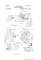
- Fig. .2 is a similar view showing a modified arrangement of operating devices embodying my invention.
- Fig. 3 is a view illustrating means for controlling the operating mechanism from the car.
- Fig. 4 is a view in side elevation of the operating-mechanism-controlling devices shown in Fig. 3, parts in vertical section.
- Fig. 5 is a diagrammatic detail'view. of the form of regulating-rheostat shown in Fig. 1.
- Fig. 6 is a similar view of the form of regulating-rheostat shown in Fig. 2.
- I provide a suitable electric motor capable of producing positive motion and connect the same to the door in such manner that by completing the electric circuit through the motor in one direction the door is opened and by completing such current through the motor in the opposite direction the door is closed.
- a suitable electric motor capable of producing positive motion and connect the same to the door in such manner that by completing the electric circuit through the motor in one direction the door is opened and by completing such current through the motor in the opposite direction the door is closed.
- an electric motor may be employed for moving the door only in one direction and other suitable means employed for moving the door in the opposite direction. I prefer, however, to employ a motor which positively moves the door in both directions.
- a motor 7 comprising a solenoid made up of sections A, B, O, D, and E of coils.
- This solenoid is mounted on the stationary part of the framework or casing of the elevator shaft or well over the door.
- the core of the solenoid which is arranged to move back and forth through the sections of coils when said coils 'are suitably energized, comprises a p1unger-rod 8 and is connected to a swinging lever 10 at a point intermediate the ends thereof, as by means of the link 9.
- the swinging lever 10 is pivotally mounted or hung at one end thereof, as at 11, to a fixed part of the casing'or framing of the elevator shaft or well, and at the other end thereof is pivotally connected to a block 12, mounted to slide upon a bar 13, secured in a suitable and convenient position upon the edge of the door F.
- the door F is suitably suspended, as by means of the hangers G, from a bar H, whereby said door maybe slid back and forth on said bar. From this construction it will be seen that when the plunger-rod '8 is moved in one or the other direction the door is also moved correspondingly, the sliding of block 12 upon the bar 13 permitting the necessary movement of the lever 10 relative to the door during such movement.
- an arm or link 14 Connected to the swinging lever 10 to move therewith is an arm or link 14, having the other end thereof connected to an arm of the rheostat 16, whereby the said rheostatarm 15 moves coincident with and in the same direction as the core-plunger 8 of solenoid 7.
- this coincident movement of the rheostat-arm 15 and plunger-core 8 may be secured in any other suitable or convenient connection between said plunger-core and arm, the essential object being to secure a unison of movement between such core and arm.
- Reference-sign 17 designates a controllingswitch suitably mounted in the shaft or well framing and having a switch-arm 19 pivotally mounted thereon.
- Carried by said switcharm 19 is a lug or projection 18, arranged to project into the well or shaft and into position to be engaged by a shoe 20, carried by the car when desired, whereby said switcharm 19 is swung into position to make the desired connections of the solenoid-circuit.
- the shoe 20, carried by the car be under the control of the car-conductor in order that the said conductor may control the movement of the doors throughout the length of the well or shaft.
- the shoe 20 may be held normally in position to be out of alinement with the projection 18, in order that the car may pass any particular door without opening the same. This may be accomplished in anysuit-able or convenient manner, as by connecting a spring 23 at one end to bar K and the other end to bar J, the normal action of said spring being to maintain the bell-cranks 21 in position to hold shoe 20 folded back out of the path of the projection 18 of the controlling-switch of each door.
- the rheostat 16 carries two contact-strips 30 31. (See particularly Fig. Adjacent to the strip 30 are a series of contact-points 32 33 34 35 36, corresponding in number to the number of sections A B O D E of the solenoid, and adjacent to strip 31 are a similar number of contact-points 37 38 39 it) 11.
- the rheostat-arm 15 carries two brushes, one of which is arranged to bridge the space between strip 30 and the contacts 32 33 31 35 3G,
- the contacts 32, 33, and 36 are respectively included in circuit, through connections 0, d, and 6, with the windings of sections D, O, and A of the solenoid, a resistance -l-l being included in the connection 8, and contacts 34 and 35 are both included in circuit, through wire f, with the windings of section B of the solenoid, a resistance 43 being interposed in the circuit of contact 35 and a resistance 42 being interposed in the circuit of contact 34.
- the current may be supplied from any suitable source.
- op IIO By way of illustration of an op IIO The operation and electrical action of the apparatus so far described will now be fully explained.
- the elevator-conduetor desires to open any particular door, he actuates the treadle or push-button 25 as he approaches or arrives adjacent to the particular door to be opened, thereby rocking the lever 24, and hence projecting the arm or bar K endwise against the action of spring
- This movement of said bar effects a rocking of the bell-crank arms 21 about their pivots, and thereby the shoe 20 is projected into the path of projection 18, and hence if the car is adjacent to the door or when it arrives adjacent to the door the projection 18 is engaged by such shoe 20 and is moved out of its normal position, thereby swinging the switch-arm 19 out of the contact with point 28 and into contact with point 29, such movement of the switch arm being against the action of spring 26.
- switch-arm 19 with contact 29, thereby bridging the space between the strip 27 and said point 29, completes the following circuit: from the source of current-supply through connection 49, strip 27, arm 19, point 29, wire I) to strip 30 on the rheostat, and thence through the brush on arm 15 to contact 32, wire 0, the coils of section D of the solenoid, and thence returning to the source of energy through wire 50.
- the energization of the section D of the solenoid by the passage of the current therethrough effects a drawing of.
- This may be effected by interposing increasing resistances 42 43 44 in the successive circuits of the successive sections of coils of the solenoid, and by decreasing the electrical energy of the exciting-current as the door approaches the limit of its movement of course the force with which the plunger 8 is drawn into and through the successive coils is correspondingly decreased, and thus the door may be brought to a stop in open position without material shock or jar.
- the same result may also be obtained by so relatively arranging the contacts at the end of the swinging movement of the rheostat-arm 15 that two or more of the sections of solenoid-coils are simultaneously cut into live-circuit, thereby interposing a magnetic resistance to the advancement of the plunger-' core into and through the coils.
- the resistance 44 maybe so proportioned that the power exerted by such coil A upon the core 8 may be just sufficient to bring the door gently to the end of' its travel, and as the door reaches the end of its travel the arm 15 passes beyond the contact 36 and thereby breaks the electric connections completely.
- the elevator-conductor merely releases the button or tread 25, thereby withdrawing the shoe 20 and hence permitting the switch-arm 19 to return to its normal position, again establishing contact with point 28.
- Current therefore passes from the source of energy through connection 49, strip 27, arm 19, point 28, and connection a to strip 31 of the rheostat, and from thence through the other brush on rheo- ICC IIO
- stat-arm 15 to point 37, wire 9, and the windings of section B of the solenoid and thence to return-wire 50, thereby drawing the coreplunger 8 outwardly and in a direction to close the door.
- the operation of successively and progressively cutting in the several sec tions of the solenoid-coils and of cushioning the door electrically and magnetically in closing is the same as above described and hence does not require specific repetition of the description thereof.
- FIG. 2 I have shown in Fig. 2 and diagrammatically in Fig. 6 another form of motor and electrical operating means embodying the principles of my invention.
- I mount a suitable revolving motor 51 of any suitable type upon a stationary part of the framing of the elevator shaft or well in convenient position-say over the door F--and I arrange a gear 52 on the shaft of said motor to mesh with and to drive a wheel 53, suitably journaled.
- a connecting-link 9 similar to the corresponding part above described with reference to the construction shown in Fig. 1, is pivot-ally connected at one end to said wheel and at the other to the lever 10, which is connected to the door F, as above explained.
- a brakewheel 73 Suitably mounted upon the motor-shaft is a brakewheel 73, and a cooperating brake-shoe 74 is arranged to operate thereon.
- the brakeshoe may be applied to the brake-wheel in any suitable or convenient manner.
- a magnet 75 may be arranged in such relative position that when energized said brake-shoe is thereby applied to or released from the brake-wheel. It is evident that this may be accomplished in many diiferent ways. I have, however, shown an arrangement wherein the energization of magnet 75 applies the brake.
- the rheostat-contact 63 is included in circuit, through wires 0 c ,with the motor-brush 76, and the rheostatcontact 68 is included in circuit,through wires d d with the other motor-brush 77, and through a wire d said brush 77 is connected to theswitch-point 60, and similarly the brush 7 6 is connected,through wires 0 0 with the switch-point 57.
- the motor thereupon begins to revolve in the opposite direction, and hence through the connections described the door begins to close.
- the rheostatarm begins to move, and, contacting successively with the contacts 69 70 71 72 as the motorcontinues to revolve, the increasing resistances 82 83 84 85 are successively cut into the rheostat-circuit until finally the resistance of this circuit is increased to such a point with reference to the circuit of magnet 75 that a sufficient amount of current passes through the magnet-circuit to energize the same and to apply the brake. This occurs gradually, and hence the door is closed gently and without shock or jar.
- a door an electric motor and connections between the motor and door, of a switch for controlling the motor-circuit having a projection, a shoe carried by the car and normally held out of alinement with said projection, and meansunder the control of the car-conductor for moving said shoe into position to engage and actuate said switch, as and for the purpose set forth.
- a door a sectional solenoid having a movable connections between the door and core a switch, means actuated from the car for operating said switch and means actuated by the movements of the door for cutting in resistances in the circuit of the solenoid, as and for the purpose set forth.
Description
(No Model.) 3 SheetsSheet 1.
H. ROWNTREE.
DOOR OPERATING DEVICE No. 596,019. Patented Dec. 21, 1897.
ATTORNEY5 WITNESSES: MVM
1m: nonms FEIERS co, mom-urns wasumcrou u. c,
(No Model.)
. v 3 Sheets'Sheet 2. H. ROWNTRElL' DOOR OPERATING DEVICE. No. 596,019.. Patented Dec. 21, 1897.
Tic- .2
Fla- E J I J WITNESSES: MENTOR ATTORNEYS 7H: nonms PETERS no. PHOTO-LITHO., w SHKNGTON. D. c
(No Model.) 3 Sheets-Sheet 3'. v H. ROWNTREE.
DOOR OPERATING DEVICE.
Patented Dec. 21, 1897.
My lNVE TOR ATTORNEYS WITNESSES: v
ma NORRIS PUERS 00.. PNOTOLITHQ, WASHlNGTON, u. c.
Enron.
PATENT HAROLD ROWNTREE, OF CHICAGO, ILLINOIS.
DOOR-OPERATING DEVICE.
SPECIFICATION forming part of Letters Patent No. 596,019, dated December 21, 1897.
Application filed April 24, 1897. Serial No. 633,785. (No model.)
T alt whom, it may concern.-
Be it known that I, 'HAROLD ROWNTREE, a citizen of'the United States, residing at Chicago, in the county of Cook and State of Illivide means under the control of the elevatorconductor for moving a door by electric energy.
A further object of the invention is to provide means for cushioning an electrically-operated door at the limits of movement thereof.
Further objects of the invention will appear more fully hereinafter.
The invention consists, substantially, in the construction, arrangement, combination, and location of parts, all as will be more fully hereinafter set forth, as shown in the accompanying drawings, and finally specifically pointed out in the appended claims.
Referring to the accompanying drawings and to the various views and reference-signs appearing thereon, Figure 1 is a View in front elevation of a door and operating devices therefor embodying the principles of my invention, showing in full and in dotted lines the door in different limits of its movements. Fig. .2 is a similar view showing a modified arrangement of operating devices embodying my invention. Fig. 3 is a view illustrating means for controlling the operating mechanism from the car. Fig. 4 is a view in side elevation of the operating-mechanism-controlling devices shown in Fig. 3, parts in vertical section. Fig. 5 is a diagrammatic detail'view. of the form of regulating-rheostat shown in Fig. 1. Fig. 6 is a similar view of the form of regulating-rheostat shown in Fig. 2.
' The same part is designated by the same reference-sign wherever it occurs throughout the several views.
In carrying out my invention I provide a suitable electric motor capable of producing positive motion and connect the same to the door in such manner that by completing the electric circuit through the motor in one direction the door is opened and by completing such current through the motor in the opposite direction the door is closed. Of course it is evident that many different forms of motors may be employed and still fall within the spirit and scope of my invention and also that an electric motor may be employed for moving the door only in one direction and other suitable means employed for moving the door in the opposite direction. I prefer, however, to employ a motor which positively moves the door in both directions.
In the drawings and as illustrative of the generic conception of my invention I have shown two forms of motors.
In Fig. 1 is shown a motor 7, comprising a solenoid made up of sections A, B, O, D, and E of coils. This solenoid is mounted on the stationary part of the framework or casing of the elevator shaft or well over the door. The core of the solenoid, which is arranged to move back and forth through the sections of coils when said coils 'are suitably energized, comprises a p1unger-rod 8 and is connected to a swinging lever 10 at a point intermediate the ends thereof, as by means of the link 9. The swinging lever 10 is pivotally mounted or hung at one end thereof, as at 11, to a fixed part of the casing'or framing of the elevator shaft or well, and at the other end thereof is pivotally connected to a block 12, mounted to slide upon a bar 13, secured in a suitable and convenient position upon the edge of the door F. The door F is suitably suspended, as by means of the hangers G, from a bar H, whereby said door maybe slid back and forth on said bar. From this construction it will be seen that when the plunger-rod '8 is moved in one or the other direction the door is also moved correspondingly, the sliding of block 12 upon the bar 13 permitting the necessary movement of the lever 10 relative to the door during such movement.
I will now describe the electrical connections whereby the several sections A B O D E of the solenoid are energized in the proper manner to effect the proper movement of the core 8.
Connected to the swinging lever 10 to move therewith is an arm or link 14, having the other end thereof connected to an arm of the rheostat 16, whereby the said rheostatarm 15 moves coincident with and in the same direction as the core-plunger 8 of solenoid 7. Of course this coincident movement of the rheostat-arm 15 and plunger-core 8 may be secured in any other suitable or convenient connection between said plunger-core and arm, the essential object being to secure a unison of movement between such core and arm.
Reference-sign 17 designates a controllingswitch suitably mounted in the shaft or well framing and having a switch-arm 19 pivotally mounted thereon. Carried by said switcharm 19 is a lug or projection 18, arranged to project into the well or shaft and into position to be engaged by a shoe 20, carried by the car when desired, whereby said switcharm 19 is swung into position to make the desired connections of the solenoid-circuit. It is important that the shoe 20, carried by the car, be under the control of the car-conductor in order that the said conductor may control the movement of the doors throughout the length of the well or shaft. In other words, it is desirable to so mount the shoe that the car-conductor may control the circuits of the motor to the end that any particular door maybe opened as the cararrives adjacent to that door, or the car may proceed upon its travel without any particular door being opened, as occasion may require. To this end I mount the shoe 20 upon bell-crank levers 2l,said levers being supported pivotally upon a bar or other suitable or convenient part J of the car, and to the other arms of the bell-crank levers 21 I connect a bar K, having suitable connection 22 with a foot-lever or treadle 2st, carried by the ear in convenient position for the car-conductor to de press or rock the same through a tread portion or push-button 25.
The shoe 20 may be held normally in position to be out of alinement with the projection 18, in order that the car may pass any particular door without opening the same. This may be accomplished in anysuit-able or convenient manner, as by connecting a spring 23 at one end to bar K and the other end to bar J, the normal action of said spring being to maintain the bell-cranks 21 in position to hold shoe 20 folded back out of the path of the projection 18 of the controlling-switch of each door. hen, however, it is desired to open any particular door, as the car approaches the particular door to be opened the conductor actuates the foot-lever 2-:t, thereby effecting an endwise movement of bar K against the action of spring 23 and in a direction to rock or swing the bell-crank arms 21 about their point of pivotal support upon bar J and thereby projecting the shoe 20 into the path of projection 18, and hence effecting a rocking of the switch-arm 19, by which the solenoid-circuits are controlled. From this description it is obvious that so long as the car remains adjacent to any floor the conductor can control the switch-arm 19, said arm being normally held in one limit of its movement by means of spring 26 and being moved from such normal position by the engagement with the projection 18 of the shoe 20 when projected as above described. As the shoe 20 is withdrawn the switch-arm 19 is returned to its normal or initial position by the spring 26.
The switchboard 17 carries a contact-strip 27 and the contacts 28 20, so relatively arranged that when the switch-arm 19 is in its normal position it makes electrical connection between the point 28 and the strip 27, but when moved by the shoe 20 this connection is broken and electrical connection is established between point 29 and strip 27 through the switch-arm 19.
The rheostat 16 carries two contact-strips 30 31. (See particularly Fig. Adjacent to the strip 30 are a series of contact-points 32 33 34 35 36, corresponding in number to the number of sections A B O D E of the solenoid, and adjacent to strip 31 are a similar number of contact-points 37 38 39 it) 11. The rheostat-arm 15 carries two brushes, one of which is arranged to bridge the space between strip 30 and the contacts 32 33 31 35 3G,
and the other of said brushes is arranged to bridge the space between the strip 31 and the brushes 37 38 39 4O 41. The contact 28 on the switchboard 17 is in electrical connection, through wire a, with strip 31 of rheostat 16, and the contact 29 is in electrical connection, through wire I), with the rheostat-stri p 30. The contacts 32, 33, and 36 are respectively included in circuit, through connections 0, d, and 6, with the windings of sections D, O, and A of the solenoid, a resistance -l-l being included in the connection 8, and contacts 34 and 35 are both included in circuit, through wire f, with the windings of section B of the solenoid, a resistance 43 being interposed in the circuit of contact 35 and a resistance 42 being interposed in the circuit of contact 34. Similarly the rheostat-contacts 37, 3S, and 11 are respectively included in circuit with the windings of sections 13, C, and E of the solenoid through wires 9, 7L, and a, respectively, a resistance 47 being interposed in the circuit of contact 41, and the contacts 39 and 410 are both included in circuit, through wire m, with the windings of section D of the solenoid, a resistance 45 being included in the circuit of contact 39, and a resistance 46 is interposed in the circuit of contact 40.
The current may be supplied from any suitable source. By way of illustration of an op IIO The operation and electrical action of the apparatus so far described will now be fully explained.
If the elevator-conduetor desires to open any particular door, he actuates the treadle or push-button 25 as he approaches or arrives adjacent to the particular door to be opened, thereby rocking the lever 24, and hence projecting the arm or bar K endwise against the action of spring This movement of said bar effects a rocking of the bell-crank arms 21 about their pivots, and thereby the shoe 20 is projected into the path of projection 18, and hence if the car is adjacent to the door or when it arrives adjacent to the door the projection 18 is engaged by such shoe 20 and is moved out of its normal position, thereby swinging the switch-arm 19 out of the contact with point 28 and into contact with point 29, such movement of the switch arm being against the action of spring 26. The contacting of switch-arm 19 with contact 29, thereby bridging the space between the strip 27 and said point 29, completes the following circuit: from the source of current-supply through connection 49, strip 27, arm 19, point 29, wire I) to strip 30 on the rheostat, and thence through the brush on arm 15 to contact 32, wire 0, the coils of section D of the solenoid, and thence returning to the source of energy through wire 50. The energization of the section D of the solenoid by the passage of the current therethrough effects a drawing of.
the core-plunger 8 into the said coil, so that said core will occupy a medial position with reference to the coil-that is, the core-plunger will be drawn through coil D until the ends thereof project an equal distance from the respective sides of the coil. This movement of the core-plunger, however, effects a coincident movement of arm 15 of the rheostat and also a movement of the door toward open position through the connections above explained, thereby breaking the circuit through contact 32 and immediately making the circuit from 30 (strip) to contact 33 and thence through wire at and the windings of section 0 of the solenoid, thereby energizing said section, and hence effecting a further movement into or through the solenoid-coils of the plunger-core 8, with a further movement of the door toward open position and a corresponding coincident movement of arm 15. This movement. of arm 15 in a manner similar to that above described breaks the circuit through the windings of section 0 of the solenoid and at the same time completes the circuit of the next section of the solenoid, and so on until the door is finally opened. As the door approaches the limit of its movement toward open position, it is desirable to interpose a cushion in order to avoid slamming or jarring the same. This result may be accomplished in several ways. For instance and by way of illustration of the principle involved, the electrical energy of the excitingcurrent may be decreased as the end sections of the solenoid are reached and cut into circuit. This may be effected by interposing increasing resistances 42 43 44 in the successive circuits of the successive sections of coils of the solenoid, and by decreasing the electrical energy of the exciting-current as the door approaches the limit of its movement of course the force with which the plunger 8 is drawn into and through the successive coils is correspondingly decreased, and thus the door may be brought to a stop in open position without material shock or jar. The same result may also be obtained by so relatively arranging the contacts at the end of the swinging movement of the rheostat-arm 15 that two or more of the sections of solenoid-coils are simultaneously cut into live-circuit, thereby interposing a magnetic resistance to the advancement of the plunger-' core into and through the coils. Thus as the rheostat-arm 15 is breaking connection with point 34 it makes connection with point 35, which, as above explained, is included in circuit with the same section B of solenoid coils. The plunger-core 8, however, by this timeis so far into the solenoid that the current still passing through the section B has ceased to produce a forward pull on the plunger, and hence the natural forward movement of such plunger, due to any momentum developed by the movement of the door up to this point, is counteracted by the retarding influence of the. energized section B of the solenoid on said core, and the longer or more extended in length this contact 35 the longer the brush of the rheostat-arm 15 will remain in contact therewith, and hence the longer will this magnetic restraining influence be exerted upon the core, thereby slacking the speed of movement of the door and avoiding shock and jar at the final limit of its movement to open position. Of course the resistance 42 43 44 may be made large or small and of any desired relation to each other in order to secure any desired degree of cushioning effect, or they may be omitted altogether and the magnetic cushioning used alone. When the rheostat-arm 15 finally rests only upon the last contact 36, thereby completing the circuit of the last section A of the solenoidal coils, the resistance 44 maybe so proportioned that the power exerted by such coil A upon the core 8 may be just sufficient to bring the door gently to the end of' its travel, and as the door reaches the end of its travel the arm 15 passes beyond the contact 36 and thereby breaks the electric connections completely.
WVhen it ,is desired to close the door, the elevator-conductor merely releases the button or tread 25, thereby withdrawing the shoe 20 and hence permitting the switch-arm 19 to return to its normal position, again establishing contact with point 28. Current therefore passes from the source of energy through connection 49, strip 27, arm 19, point 28, and connection a to strip 31 of the rheostat, and from thence through the other brush on rheo- ICC IIO
stat-arm 15 to point 37, wire 9, and the windings of section B of the solenoid and thence to return-wire 50, thereby drawing the coreplunger 8 outwardly and in a direction to close the door. The operation of successively and progressively cutting in the several sec tions of the solenoid-coils and of cushioning the door electrically and magnetically in closing is the same as above described and hence does not require specific repetition of the description thereof.
The solenoid 7 may be divided into as many sections as may be desired, always maintaining the same relative number and arrangement of contact-points on the rheostat, and the point at which the electrical energy of the energizing current is begun to be reduced or at which the magnetic retardation of the solenoid-core commences may be varied at will and still fall within the spirit and scope of my invention.
I have shown in Fig. 2 and diagrammatically in Fig. 6 another form of motor and electrical operating means embodying the principles of my invention. In this case I mount a suitable revolving motor 51 of any suitable type upon a stationary part of the framing of the elevator shaft or well in convenient position-say over the door F--and I arrange a gear 52 on the shaft of said motor to mesh with and to drive a wheel 53, suitably journaled. A connecting-link 9, similar to the corresponding part above described with reference to the construction shown in Fig. 1, is pivot-ally connected at one end to said wheel and at the other to the lever 10, which is connected to the door F, as above explained. From this it will be seen that when the motor is actuated the wheel 53 is rotated, there by effecting an opening and closing of the door. In this form of arrangement the rheostat 54 is arranged in proximity to the wheel 58, and the brush-carrying rheostat-arm,
which makes and breaks the circuit through the various contacts of the rheostat, is mounted on to rotate with the wheel53. The switch 17, with its pivoted arm 19 and projection 18 and the spring 26, is substantially identical with the corresponding parts above described, and said switch-arm 19 is actuated from the car by shoe 20 in identically the same manner as hereinafter described. In the case of a revolving motor, however, it is necessary that both leading-wires 4:9 from the source of power 48 be connected to the switchboard 17. I therefore provide said switchboard with one contact 55, which forms the terminal, through connection 49, of one pole of the its normal position,the contacts 55 and 56 are respectively in electrical connection, through brushes carried by said arm 19, with the contacts 57 58. When, however, the arm 19 is thrown out of its normal position and against the action of spring 26 by the shoe 20, as above described, these electrical connections are broken and the contacts 55 56 are respectively brought into electrical connection with the points 60 59. Upon the rheostat 54 are mounted the contactstrips 61 62, (see Fig. 6,) corresponding in function and arrangement to the strips 30 31 of rheostat 16, and adjacent to the strip 61 and in cooperative relation therewith are several contacts 63, 64, 65, 66, and 67, respectively coupled up in series with the increasing resistances 78 79 81, respectively interposed between said contacts. Similarly adjacent to strip 62 and in cooperative relation therewith are the severalcontacts 68 69 7O 71 72 with the respectively interposed increasing resistances 82 S3 84E 85. Suitably mounted upon the motor-shaft is a brakewheel 73, and a cooperating brake-shoe 74 is arranged to operate thereon. The brakeshoe may be applied to the brake-wheel in any suitable or convenient manner. For instance, a magnet 75 may be arranged in such relative position that when energized said brake-shoe is thereby applied to or released from the brake-wheel. It is evident that this may be accomplished in many diiferent ways. I have, however, shown an arrangement wherein the energization of magnet 75 applies the brake. I do not desire to be limited, however, to the particular arrangement, the essential feature being the utilization of means for retarding and counteracting the electric operative means, the said means (in this case the brake) being normally inoperative while the door is in motion, but which is brought into operation as the door nears the end of its travel, as is more fully hereinafter described and explained. The magnet 75: is doublewound-that is, it is wound with two wires, so that it may be energized by a current passing through either of said wires. The point 59 of the switch is included in circuit, through Wires a a with strip 61 of the rheostat, and switch-contact 58 is included in circuit, through wires Z) W, with the rheostat-strip 62. The rheostat-contact 63 is included in circuit, through wires 0 c ,with the motor-brush 76, and the rheostatcontact 68 is included in circuit,through wires d d with the other motor-brush 77, and through a wire d said brush 77 is connected to theswitch-point 60, and similarly the brush 7 6 is connected,through wires 0 0 with the switch-point 57. The wire a, connecting point 59 with strip 61 through wire a has a branch (1 which is included in circuit with one of the windings of magnet 75, and thence connects,through wire a, to wire c ,and thence to motor-brush 76, and a similar wire 1), connecting point 58 with strip 62 through wire 17 has a branch D which is included in circuit with the other winding of magnet 75, and thence connects, through wire I), to wire (2*, and thence to motor-brush 77. The operation of this form of mechanism and arrangement embodying my invention is as follows:
WVhen by means of shoe 20, as above described, the car-conductor throws switch-arin 19 out'of its normal position, the contacts 55 56 are respectively connected electrically through the brushes carried by said arm to the points 60 59. Current therefore flows from the supply-wire to point 56, to point 59, wire a, then dividing, part proceeding through wire a to strip 61 on the rheostat, thence through one of the brushes on the rheostat-arm to contact 63, wire 0, Wire 0 to brush 76. The other part of the current passes through wire a, wire a one of the windings of magnet 75, wire a, wire 0 to brush 76. The current has therefore two paths, either or both of which it may follow to brush 76. However, as the resistance of the magnet-circuit is much greater than that of the other circuit a very small portion of the current will flow through the magnetwindings, and therefore insufficient to efiect an energization of the magnet. From brush 7 6 the current proceeds through the motorwindings to brush 77 thence through wire 02 to switch-point 60, thence through the switcharm brush to point and to the other leading-wire 49. This completes the motor-circuit and the motor begins to revolve, and
' hence through the gear 52, wheel 53, link 9,
and lever 10 the door begins to open. The revolution of wheel 53 carries with it the rheostat arm and brush, which by the travel thereof over the face of the rheostat thereby breaking the circuitdirect from strip 61 to contact 63 and making the circuit between said strip and contact through contact 64 and the interposed resistance 78, and thence on to the motor, as above-described. Thus as the motor continues to revolve the traveling brush of the rheostat-arm successively cuts into the motor-circuit the resistance 78 79 80, &c., as the said arm and brush continues on its travel. The farther the wheel 53 revolves, and hence the nearer the door approaches the limit of its movement toward open position, the more resistance will be cut in the motor-circuit, and consequently the slower the motor will revolve. It will also be seen that the. more resistance cut into the motor-circuit through the rheostat the less will the resistance of the magnet-circuit exceed that of the rheostat circuit, until finally a sufficient amount of current will pass through the magnet-circuit to energize said magnet, and thereby efiect an application of the brake, thereby retarding the motor, and hence bringing the door to rest gently and without shock or jar at the limit of its open movement. When it is desired to close the door, the conductor releases the shoe 20, thereby permitting the same to return to its normal position, and hence permitting the switch-arm 19 to also return to its normal position, breaking the circuits through switchpoints 59 and establishing circuits through switch-points 58 57. Current will thereupon pass from supplywire 50 to point 58, then to wire I), and dividing, part going through wire 5 to strip 62, the rheostat-brush to contact 68, wire d, wire 61 to brush 77, and. part through wire 5 the other winding of magnet 75, wire 5 wire (1 to brush 77. As the resistance of this last-mentioned circuit exceeds that of the rheostat-circuit, the brake-magnet is unaffected, and hence in the particular form shown the brake is not applied. From the brush 77 the current proceeds through the windings of the motor in the opposite direction to that above described to brush 76, thence through wire 0 and wire 0 to switchpoint 57, to point 55, and to return-wire 49. The motor thereupon begins to revolve in the opposite direction, and hence through the connections described the door begins to close. Coincident with this movement the rheostatarm begins to move, and, contacting successively with the contacts 69 70 71 72 as the motorcontinues to revolve, the increasing resistances 82 83 84 85 are successively cut into the rheostat-circuit until finally the resistance of this circuit is increased to such a point with reference to the circuit of magnet 75 that a sufficient amount of current passes through the magnet-circuit to energize the same and to apply the brake. This occurs gradually, and hence the door is closed gently and without shock or jar.
It is believed that the principles of my. invention will be fully understood from the foregoing description. Of courseit will be understood that many different specific forms of apparatus may be devised for carrying the principles of my invention into practical effect. While, therefore, I have shown illustrative embodiments of means, I wish it to be understood that I do not limit or confine myself to the specific construction, arrangement, and details of parts shown and described, as many changes therein and variations therefrom would readily suggest themselves to persons skilled in the art and still fall within the spirit and scope of my invention; but,
Having now set forth? the objects and nature of my invention and various forms of apparatus embodying the same, and having described the construction, function, and mode of operation thereof, whatI claim as new and useful and of my own invention, and desire to secure by Letters Patent of the United States, is-
1. The combination of an elevator, a door, electric means for operating the door, and means for decreasing the force of the electric means as the door nears the end of its travel, substantially as described.
2. The combination of an elevator, a door, electric means for operating the door, and means whereby the electric operating means are changed into electric retarding means as the door nears the end of its travel, substantially as described.
3. The'combination of an elevator, a door,
an electric motor, connections between said motor and door whereby when said motor is actuated said door is moved to open or closed position, and electrically-operated means actuated by the movement of the door for re tarding the movement of the door as it approaches the limit of its movement, substantially as described.
4. The combination of an elevator, a door, electric means for operating the door, electric means for retarding the operation of the door and means for increasing the force of ihe electric retarding means as the door nears the end of its travel, substantially as described.
5. The combination of an elevator, a door, electric means for operating the door, and means for counteracting the force of the elec tric operating means as the door nears the end of its travel, substantially as described.
(3. The combination of an elevator, a door, electric means for operating the door, a rheostat controlling the electric means and connections between the rheostat and the door whereby the rheostat decreases the force of the electric means as the door nears the end of its travel, substantially as described.
7. The combination of an elevator, a door, electric means for operating the door, a rheostat for controlling the electric means and connections between the rheostat and door whereby the electric operating means are changed into electric retarding means as the door nears the end of its travel, substantially as described.
8. The combination of an elevator, a door, electricmeans for operating the door, electric means for retarding the operation of the door, a rheostat for controlling the electric operating means and the electric retarding means and connections between the rheostat and the door, substantially as described.
9. The combination of an elevator, a door, electric means for operating the door, electric means for retarding the door, a rheostat for controlling the electric operating means and the electric retarding means and coun ections between the rheostat and door Whereby the force of the electric retarding means is increased as the door nears the end of its travel, substantially as described.
10. The combination of an elevator, a door, a solenoid for operating the door, and means for decreasing the operating force of the solenoid as the door nears the end of its travel, substantially as described.
11. The combination of an elevator, adoor, a solenoid for operating the door and means whereby the operating force of the solenoid is changed into a retarding force as the door nears the end of its travel, substantially as described.
12. The combination of an elevator, a door, a solenoid for operating the door, a rheostat controlling the solenoid and connections between the rheostat and the door whereby the rheostat decreases the operating force of the solenoid as the door nears the end of its travel, substantially as described.
13. The combination of an elevator, a door, a solenoid for operating the door, a rheostat for controlling the solenoid and connections between the rheostat and door whereby the operating force of the solenoid is changed into a retarding force as the door nears the end of its travel, substantially as described.
14. The combination of an elevator, a door, a solenoid for operating thedoor, a rheostat for controlling the solenoid and means for counteracting the operating force of the solenoid as the door nears the end of its travel, substantially as described.
15.. The combination of an elevator, a door, a movable shoe on the car, electric means for operating the door arranged to be thrown into action by said shoe and means for decreasing the force of the electric means as the door nears the end of its travel, substantially as described.
16. The combination of an elevator, a door, a movable shoe on the car, electric means for operating the door arranged to be thrown into action by said shoe, and means whereby the electric operating means are changed into electric retarding means as the door nears the end of its travel, substantially as described.
17. The combination of an elevator, a door, a movable shoe on the car, electric means for operating the door arranged to be thrown into action by said shoe, and electric means for retarding the operation of the door, substantially as described.
18. The combination of an elevator, a door, a movable shoe on the car, electric means controlled by said shoe for operating the door, electric means for retarding the operation of the door and means for increasing the force of the electric retarding means as the door nears the end of its travel, substantially as described.
19. The combination of an elevator, a door, a movable shoe on the car, electric means controlled by said shoe for operating the door, and means for counteracting the force of the electric operating means as the door nears the end of its travel, substantially as described.
20. The combination of an elevator, a door, a movable shoe on the car, electric means for operating the door, a rheostat controlling the electric means said rheostat actuated by said shoe and connections between the rheostat and the door whereby the rheostat decreases the force of the electric means as the door nears the end of its travel, substantially as described.
21. The combination of an elevator, a door, a movable shoe 011 the car, electric means for operating the door, a rheostat for controlling the electric means said rheostat actuated by said shoe and connections between the rheostat and door whereby the electric operating means are changed into electric retarding means as the door nears the end of its travel, substantially as described.
IIO
22. The combination of an elevator, a door, a movable shoe on the car, electric means for operating the door, electric means for retarding the operation of the door, a rheostat for controlling the electric operating means and the electric retarding means said shoe arranged to actuate said rheostat and connections between the rheostat and the door, substantially as described.
23. The combination of an elevator, a door, a movable shoe on the car, electric means for operating the door, electric means for retarding the door, a rheostat for controlling the electric operating means and the electric retarding means said shoe arranged to actuate said rheostat and connections between the rheostat and door whereby the force of the electric retarding means is increased as the door nears the end of its travel, substantially as described.
24. The combination of an elevator, a door, a movable shoe on the car, a solenoid for operating the door, said shoe arranged to control the circuits of said solenoid and means for decreasing the operating force of the solenoidas the door nears the end of its travel, substantially as described.
25. The combination of an elevator, a door, a movable shoe on the car, a solenoid for op erating the door said shoe arranged to control the circuits of said solenoid and means whereby the operating force of the solenoid is changed into a retarding force as the door nears the end of its travel, substantially as described.
26. The combination of an elevator, a door, a movable shoe on the car, a solenoid for operating the door, a rheostat controlling the solenoid said shoe arranged to actuate said rheostat and connections between the rheostat and the door whereby the rheostat decreases the operating force of the solenoid as the door nears the end of its travel, substantially as described.
27. The combination of an elevator, a door, a movable shoe on the car, a solenoid for operating the door, a rheostat for controlling the solenoid said shoe arranged to actuate said rheostat and connections between the rheostatand door whereby the operating force of the solenoid is changed into a retarding force as the door nears the end of its travel, substantially as described.
28. The combination of an elevator, a door, a movable shoe on the car, a solenoid for operating the door, a rheostat for controlling the solenoid said shoe arranged to actuate said rheostat and means for counteracting the operating force of the solenoid as the door nears the end of its travel, substantially as described.
. 29. The combination of an-elevator, a door, electric means'for operating the door, means normally inoperative while the dooris in motion for counteracting the speed of the door, and means actuated by the door-operating means for bringing the counteracting means into operation as the door nears the end of its travel, substantially as described.
30. The combination of an elevator, a door, electric means for operating the door, a rheostat for controlling the electric means, normally inoperative means for counteracting scribed.
32. The combination of an elevator, a door, a solenoid for operating the door, means normally inoperative for counteracting the speed of the door and'means actuated by the dooroperating means for bringing the counteracting means into operation as the door nears the end of its travel, substantially as described.
33. The combination of an elevator, a door, an electric motor for operating the same, connections between said motor and door, a switch for controlling the motor-circuit, said switch arranged to extend into the elevator shaft or well, and means arranged Within the control of the elevator-conductor for actuating said switch, as and for the purpose set forth.
34. The combination with an elevator-oar,
a door, an electric motor and connections between the motor and door, of a switch for controlling the motor-circuit having a projection, a shoe carried by the car and normally held out of alinement with said projection, and meansunder the control of the car-conductor for moving said shoe into position to engage and actuate said switch, as and for the purpose set forth.
35. The combination with an elevator-car, a door, a sectional solenoid having a movable core, and connections between the door and said core, a rheostat for successively cutting the sections of said solenoid into and out of circuit, and means actuated by the movement of the door for actuating said rheostat and means carried by the car for controlling the circuit, as and for the purpose set forth. 7
36. The combination with an elevator-car,
a door, a sectional solenoid having a movable connections between the door and core a switch, means actuated from the car for operating said switch and means actuated by the movements of the door for cutting in resistances in the circuit of the solenoid, as and for the purpose set forth.
38. The combination of an elevator, at door, a solenoid for operating the door, a rheostat for controlling the solenoid, normally inoperative means for retarding the motion of the door and means for bringing the retarding means into operation as the door nears the end of its travel, substantially as described.
39. The combination of an elevator, a door,
Publications (1)
| Publication Number | Publication Date |
|---|---|
| US596019A true US596019A (en) | 1897-12-21 |
Family
ID=2664667
Family Applications (1)
| Application Number | Title | Priority Date | Filing Date |
|---|---|---|---|
| US596019D Expired - Lifetime US596019A (en) | Door-operating device |
Country Status (1)
| Country | Link |
|---|---|
| US (1) | US596019A (en) |
-
0
- US US596019D patent/US596019A/en not_active Expired - Lifetime
Similar Documents
| Publication | Publication Date | Title |
|---|---|---|
| US596019A (en) | Door-operating device | |
| US1100134A (en) | Controller. | |
| US1145881A (en) | Door-operating mechanism. | |
| US1793716A (en) | Electric-engine device for safety doors | |
| US1171518A (en) | Safety control system for elevator-cars. | |
| US600278A (en) | Automatic switch for railways | |
| US733562A (en) | Electrohydraulic controller for electric motors. | |
| US715299A (en) | Electric elevator. | |
| US609274A (en) | System of control of electric motors | |
| US1329712A (en) | Push-button control system for elevator-door-operating devices | |
| US981919A (en) | Safety device for alternating-current hoisting apparatus. | |
| US1216300A (en) | Car-door control. | |
| US1545164A (en) | Combination elevator and door control | |
| US1333240A (en) | Elevator signaling system | |
| US600252A (en) | Means for arresting motion of electric cars | |
| US834336A (en) | Automatic electric braking. | |
| US998624A (en) | Door-lock-operating apparatus. | |
| US830242A (en) | System of motor control. | |
| US531070A (en) | Controlling device for elevators | |
| US959645A (en) | Mechanically-controlled automatic elevator. | |
| US815756A (en) | System of electrical control. | |
| US1421244A (en) | Control system | |
| US1254122A (en) | Switch-operating mechanism. | |
| US505271A (en) | hicks | |
| US1552600A (en) | Control panel |