US5951426A - Hydraulically triggered limited slip differential - Google Patents
Hydraulically triggered limited slip differential Download PDFInfo
- Publication number
- US5951426A US5951426A US09/030,603 US3060398A US5951426A US 5951426 A US5951426 A US 5951426A US 3060398 A US3060398 A US 3060398A US 5951426 A US5951426 A US 5951426A
- Authority
- US
- United States
- Prior art keywords
- side gear
- cavity
- clutch
- disposed
- limited slip
- Prior art date
- Legal status (The legal status is an assumption and is not a legal conclusion. Google has not performed a legal analysis and makes no representation as to the accuracy of the status listed.)
- Expired - Fee Related
Links
Images


Classifications
-
- F—MECHANICAL ENGINEERING; LIGHTING; HEATING; WEAPONS; BLASTING
- F16—ENGINEERING ELEMENTS AND UNITS; GENERAL MEASURES FOR PRODUCING AND MAINTAINING EFFECTIVE FUNCTIONING OF MACHINES OR INSTALLATIONS; THERMAL INSULATION IN GENERAL
- F16H—GEARING
- F16H48/00—Differential gearings
- F16H48/20—Arrangements for suppressing or influencing the differential action, e.g. locking devices
- F16H48/22—Arrangements for suppressing or influencing the differential action, e.g. locking devices using friction clutches or brakes
-
- F—MECHANICAL ENGINEERING; LIGHTING; HEATING; WEAPONS; BLASTING
- F16—ENGINEERING ELEMENTS AND UNITS; GENERAL MEASURES FOR PRODUCING AND MAINTAINING EFFECTIVE FUNCTIONING OF MACHINES OR INSTALLATIONS; THERMAL INSULATION IN GENERAL
- F16H—GEARING
- F16H48/00—Differential gearings
- F16H48/06—Differential gearings with gears having orbital motion
- F16H48/08—Differential gearings with gears having orbital motion comprising bevel gears
-
- F—MECHANICAL ENGINEERING; LIGHTING; HEATING; WEAPONS; BLASTING
- F16—ENGINEERING ELEMENTS AND UNITS; GENERAL MEASURES FOR PRODUCING AND MAINTAINING EFFECTIVE FUNCTIONING OF MACHINES OR INSTALLATIONS; THERMAL INSULATION IN GENERAL
- F16H—GEARING
- F16H48/00—Differential gearings
- F16H48/20—Arrangements for suppressing or influencing the differential action, e.g. locking devices
- F16H48/27—Arrangements for suppressing or influencing the differential action, e.g. locking devices using internally-actuatable fluid pressure, e.g. internal pump types
Definitions
- the present invention relates to differentials, and more particularly, to limited slip differentials.
- the completely open differential i.e. a differential without clutches or springs
- a differential without clutches or springs is unsuitable in slippery conditions where one wheel experiences a much lower coefficient of friction than the other wheel, for instance, when one wheel of a vehicle is located on a patch of ice and the other wheel is on dry pavement.
- the wheel experiencing the lower coefficient of friction loses traction and a small amount of torque to that wheel will cause a "spin out" of that wheel.
- the maximum amount of torque which can be developed on the wheel with traction is equal to torque on the wheel without traction, i.e. the slipping wheel, the engine is unable to develop any torque and the wheel with traction is unable to rotate.
- a number of methods have been developed to limit wheel slippage under such conditions.
- Prior methods of limiting slippage between the side gears and the differential casing use a frictional clutch mechanism, either clutch plates or a frusto-conical structure, and a bias mechanism, usually a spring, to apply an initial preload between the side gears and the differential casing.
- a frictional clutch with an initial preload provided, for example, by a spring
- the initial torque generates gear separating forces which further engage the frictional clutch and develop additional torque.
- the initial preload initiates the development of side gear separating forces which provide further braking action between the side gears and the differential casing.
- gear separating forces are forces induced on any set of meshing gears by the application of torque to the gears and which forces tend to separate the gears.
- the development of torque will create side gear separating forces which tend to move the side gears away from the pinion gears.
- the initial preload creates some contact and frictional engagement between the differential casing and the clutch mechanism disposed between the side gears and the differential casing to allow the engine to provide torque to the wheel having traction.
- This initial torque transfer induces gear separating forces on the side gears which tend to separate the side gears to further frictionally engage the clutch mechanism with the casing.
- the increased frictional engagement of the clutch allows more torque to be developed, thus further increasing the side gear separating forces and limiting the slippage between the side gears and the differential casing.
- such a preloaded clutch mechanism may lock the output shafts together in situations where differential rotation is necessary. For example, if the vehicle is making a turn when the wheels are sufficiently engaged on the road surface and a sufficient amount of torque is developed, the differential will tend to lock up the output shafts due to the action of the side gear separating forces created by the developed torque.
- Another method of limiting slippage involves engaging a frictional clutch mechanism between the side gears and the differential casing based on the difference in rotational speeds between the two output shafts.
- the frictional clutch may be actuated by various hydraulic pump mechanism which may be external to the differential case or may be constructed of elements disposed inside the differential casing.
- a prior art method of limiting slippage involves using a flyweight governor in combination with a clutch mechanism wherein the governor actuates the clutch mechanism when a predetermined differential rotation rate is detected.
- prior art devices using such arrangements are configured such that the governor almost instantaneously applies extremely high clutch torque to the output shafts, essentially locking the two output shafts together. Applying locking torque in such a manner applies very high stresses on the output shafts and may result in fracturing the output shafts.
- the limited slip differential comprises a hydraulically actuated clutch mechanism which transfers a predetermined amount of clutch torque to an output element.
- the clutch mechanism is actuated by a fluid pump assembly which is disposed inside the differential casing and provides an output that depends on the rate of differential rotation between the output elements.
- the clutch mechanism is disposed between the side gear and the differential casing and includes a one clutch element disposed adjacent the side gear and an insert disposed between the cone clutch element and the differential casing.
- the cone clutch element is adapted to rotate about the axis of the side gear and also to move along the axis of the side gear.
- the insert is secured to the differential casing such that the insert cannot rotate with respect to the differential casing, but can move along the axis of the side gear.
- the cone clutch element includes a frusto-conical engagement surface which frictionally engages a complementary frusto-conical engagement surface disposed on the insert.
- the frusto-conical engagement surfaces are disengaged and the present differential is an open differential.
- the hydraulic pump assembly triggers an initial movement between the cone clutch element and the side gear. The initial movement engages the frusto-conical engagement surfaces to thereby transfer an initial amount of frictional clutch torque to the side gear.
- the cone clutch element also includes a cam portion having ramp surfaces and which engages a corresponding cam portion and ramp surfaces disposed on the side gear.
- the cam portions on the cone clutch element and side gear are fittingly engaged and the cone clutch element rotates at the same speed as the side gear.
- the limited slip feature is triggered, the initial engagement of the frusto-conical engagement surfaces causes an interaction between the cam portions which produces a predetermined amount of axial movement between the cone clutch element and the side gear.
- the axial movement of the cone clutch element also results in a corresponding axial movement of the insert.
- the predetermined axial movement transfers a predetermined amount of frictional clutch torque to the side gear.
- the amount of clutch torque transferred is selected by varying the angle of the frusto-conical engagement surfaces on the cone clutch element and the insert, and a spring located between the insert and the differential casing.
- the movement of the cone clutch element is purposely limited such that the spring does riot become solidly depressed.
- the fluid pump assembly is a simple, rugged and durable design.
- the fluid pump assembly includes a plurality of supply passages disposed in a side gear, each supply passage having an inlet disposed on the root surface of a side gear and an outlet in fluid communication with a cavity formed by the side gear and the clutch mechanism.
- the fluid pump assembly provides fluid pressure to transfer the fluid located within the root volumes of the side gear into the cavity when meshing rotation exists between the respective roots and teeth of the pinion gears and the side gears.
- a tooth of the pinion gear rotates to mesh with a root of the side gear to displace the volume of fluid held in the root volume to force that volume of fluid into the supply passage.
- the output of the pump assembly depends on the rate of meshing relative rotation between the pinion and side gears. The pumping action builds up the fluid pressure in the cavity which in turn actuates the clutch mechanism.
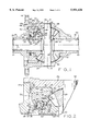
- FIG. 1 is a sectional view of an embodiment of a limited slip differential of the present invention
- FIG. 2 is an enlarged fragmentary sectional view of FIG. 1 showing a limited slip differential of the present invention in the disengaged phase;
- FIG. 3 is an enlarged fragmentary sectional view of FIG. 1 showing a limited slip differential of the present invention in the transition phase;
- FIG. 4 is an enlarged fragmentary sectional view of FIG. 1 showing a limited slip differential of the present invention in the engaged phase;
- FIG. 5 is a front elevational view of the side gear showing the supply passage inlets disposed on the surface of the side gear;
- FIG. 6 is a perspective view of the cone clutch element showing the cam portion and the ramp surfaces
- FIG. 7 is a perspective view of the side gear showing the cam portion and the ramp surfaces
- FIG. 8 is a chart illustrating the performance characteristics for a differential of the present invention with a 2500 lb. in clutch capacity
- FIG. 9 is a chart illustrating the performance characteristics for a differential of the present invention with a 5000 lb. in clutch capacity.
- FIG. 10 is a chart illustrating the performance characteristics for a differential of the present invention with a 8000 lb. in clutch capacity.
- differential casing 12 which is constructed by joining casing sections 12a and 12b to form a generally cylindrical structure having inner cavity 13.
- Inner cavity 13 is constructed to hold a differential gear assembly and includes end walls formed on the interior surfaces of casing sections 12a, 12b.
- the exterior surface of casing 12 includes flange 14 formed on one side thereof for connecting differential 10 to a driving ring gear (not shown) using conventionally known means, such as threaded fasteners (not shown).
- Casing 12 also includes hollow receiving hubs 16, 18 on each end, the hubs defining apertures 20, 22 for accepting output shafts 21, 23.
- pinion gears 28, 30 Disposed within inner cavity 13 are meshingly engaged pinion gears 28, 30 and side gears 24, 26.
- Pinion gears 28, 30 are disposed at right angles to side gears 24, 26 and are rotatably mounted on cross pin 32.
- Cross pin 32 is fixedly disposed in inner cavity 13, generally near the middle of inner cavity 13.
- Cross pin 32 is locked in position within casing 12 such that pinion gears 28, 30 rotate with casing 12 around axis 9 defined by hubs 16, 18. Pinion gears 28, 30 can also rotate around the axis of cross pin 32.
- Side gears 24, 26 are axially aligned and rotatably disposed within casing 12 to rotate about horizontal axis 9.
- Side gears 24, 26 include internal splines 25, 27 which engage corresponding splines of output shafts 21, 23.
- the roots and teeth of side gears 24, 26 meshingly engage the roots and teeth of pinion gears of 28, 30 such that differential rotation can be effected between casing 12 and output shafts 21, 23.
- cavity 60 is formed between side gears 24, 26.
- side gear 24 On the side opposite the gear teeth and roots, side gear 24 includes flange 58 which fittingly engages recessed portion 52 of cone clutch element 50.
- Side gear 24 includes recessed portion 51 formed adjacent and inward of flange 58. Recessed portion 51 in conjunction with surface 56 of cone clutch element 50 forms cavity 59.
- Cam portion 88 is disposed around side gear 24 adjacent and inward of recessed portion 51. As shown in FIG. 7, cam portion 88 includes undulating ramp surfaces 89 formed around side gear 24. Further inward of cam portion 88 is elongate portion 33 which is surrounded by cone clutch element 50 and includes end portion 35 in operative contact with casing surface 38 via thrust washer 37. Snap ring 39 is disposed in groove 34 of elongate portion 33 and serves to couple side gear 24 and cone clutch element 50 as described further below.
- the present limited slip differential includes a clutch mechanism comprising cone clutch element 50 and insert 40.
- Cone clutch element 50 is generally T-shaped in cross section and is disposed between side gear 24 and insert 40.
- Cone clutch element 50 includes frusto-conical engagement surface 55 which frictionally engages a complementary frusto-conical engagement surface 43 disposed on insert 40 to provide clutch torque when a fluid pump assembly triggers the clutch mechanism.
- Cone clutch element 50 includes recessed portion 52 which fittingly engages flange 58 of side gear 24. Inward of recessed portion 52 is planar surface 56 which in combination with recessed portion 51 forms cavity 59. Further inward of surface 56 is cam portion 91. As shown in FIG. 6, cam portion 91 includes undulating ramp surfaces 92 formed around the axis of cone clutch element 50. Cam portion 91 fittingly engages cam portion 88 of side gear 24.
- Belleville spring 49 is disposed between cone clutch element surface 54 and snap ring 39 to initially urge cone clutch element 50 to the right in FIG. 2 to force cam portions 88 and 91 into tight fitting engagement.
- the bias provided by Belleville spring 49 just holds frusto-conical engagement surface 55 from engagement with frusto-conical engagement surface 43.
- Bleed-off passages 69 which form a part of the fluid pump assembly are also disposed in cone clutch element 50.
- Bleed-off passages 69 includes passage inlets 70 in fluid communication with cavity 59 and passage outlets 71 disposed on a surface of cone clutch element 50 adjacent elongate portion 33. Bleed-off passages 69 provide a fluid path to relieve the pressure in cavity 59.
- Surrounding seal 61 is disposed between the sidewalls of cone clutch element 50 and side gear 24 to prevent fluid leakage from cavity 59 through the sidewalls of cone clutch element 50 and side gear 24. Seal 61a is located between planar surface 56 and flange 58.
- insert 40 is disposed between cone clutch element 50 and casing section 12b. Insert 40 is secured against casing section 12b such that insert 40 cannot rotate radially with respect to casing 12, but can move axially with respect to casing section 12b. Frusto-conical surfaces 43 and 55 become frictionally engaged when cone clutch element 50 initially moves axially toward casing section 12a, i.e. moves to the left in FIG. 2. The initial frictional engagement transfers an initial amount of clutch torque between casing 12 and side gear 24. Further axial movement of cone clutch element 50 caused by the interaction of cam portions 88 and 91 forces insert 40 to move axially with cone clutch element 50 toward casing section 12a, i.e. to the left.
- Belleville spring 48 is disposed between insert end portion 42 and casing section 12a to initially urge insert end portion 42 away from casing section 12a and to resist the movement of insert 40 toward casing section 12a.
- the movement limit of insert 40 and cone clutch element 50 toward casing section 12a is reached, and thus the clutch mechanism is fully engaged, when Belleville spring 48 is collapsed to a predetermined point.
- the full engagement of the clutch mechanism transfers a predetermined amount of clutch torque between casing 12 and side gear 24.
- the amount of clutch torque transferred between casing 12 and side gear 24 may be selected by varying the design characteristics of Belleville spring 48 and the configurations of the frusto-conical surfaces and ramp surfaces.
- cavity 59 which is used in conjunction with a fluid pump assembly to actuate the movement of cone clutch element 50 and insert 40.
- Cavity 59 is in fluid communication with fluid supply passages 66 which are formed on side gear 24 and form a part of a gear pump assembly with side gear 24 and pinion gears 28, 30.
- Cavity 59 is also in fluid communication with bleed-off passages 69, which are formed on cone clutch element 50.
- Fluid supply passages 66 provide a fluid source path to increase the fluid pressure in cavity 59, and bleed off passages 69 provide a fluid relief path to decrease the pressure in cavity 59.
- fluid supply passages 66 may be sized to permit a larger fluid flow rate than bleed off passages 69 to allow relatively rapid build up of fluid pressure in cavity 59, but a slower rate of fluid pressure reduction.
- Reed valve 72 is disposed in cavity 59 adjacent supply passage outlet openings 68 to ensure one-way flow through fluid supply passages 66.
- the fluid pump assembly for supplying fluid flow through fluid supply passages 66 is further described below.
- the fluid pump assembly is formed by the combination of side gear 24, pinion gears 28, 30, and fluid supply passages 66 disposed in side gear 24.
- side gear 24 includes a plurality of fluid supply passages 66, each fluid supply passage 66 including an inlet opening 67 disposed on the surface of each respective root 62 of side gear 24 and an outlet opening 68 disposed on a surface of cavity 59.
- each surface of root 62 includes an inlet opening 67, it is to be understood that the number of inlet openings as well as the ratio of inlet openings to root surfaces may be adjusted as desired and that the size of inlet openings 67 and outlet openings 68 may be adjusted as desired to provide the required fluid flow rates.
- the fluid pump assembly provides pressure to transfer fluid trapped in the root volumes of side gear 24 into cavity 59 based on the meshing rotation between side gear 24 and pinion gears 28, 30.
- side gear 24 and pinion gears 28, 30 rotate with respect to each other, about axis 9 and 8, respectively, the roots and teeth of the respective gears meshingly engage and disengage with each other.
- the pinion gear tooth displaces the volume of fluid trapped in root 62 and forces the fluid into inlet opening 67 disposed in the root surface.
- the roots and teeth of side gear 24 and pinion gears 28, 30 are angled to mesh closer at the face portion than at the base portion in order to facilitate and direct the movement of the fluid into inlet openings 67 which are disposed near the heel area of side gear 24.
- Sealing washer 57 is disposed against the heel area of side gear 24 and pinion gear 28 to reduce the loss of fluid through the heel area of side gear 24 and pinion gear 28.
- the fluid pump assembly output is speed sensitive since the pump output, and thus the rate of fluid introduction into cavity 59 through fluid supply passages 66 depends on the rate of meshing rotation between side gear 24 and pinion gears 28, 30, i.e., as the speed of meshing rotation increases, the amount of fluid transferred through fluid supply passages 66 increases. Therefore, a high rate of differential rotation between side gear 24 and pinion gears 28, 30, which indicates high differentiation between output shafts 21, 23, and a possible "spin out.” condition, results in a rapid rate of fluid introduction into cavity 59 thereby increasing fluid pressure in cavity 59 to trigger the frictional engagement of cone clutch element 50 and insert 40.
- the pressure build-up in cavity 59 provides a separation force between side gear 24 and cone clutch element 50 to move cone clutch element 50 to the left in FIG. 2, namely toward casing section 12a.
- frusto-conical engagement surfaces 43 and 55 frictionally engage.
- the frictional engagement forces cone clutch element 50 to momentarily slow down with respect to side gear 24.
- the momentary slow down in turn causes ramp surfaces 89 and 92 to ride up on each other thereby causing further axial movement between cone clutch element 50 and side gear 24 and causing frusto-conical engagement surfaces 43 and 55 to tightly engage and transfer more frictional torque.
- ⁇ coefficient of friction between the frusto-conical engagement surfaces 43 and 55;
- ⁇ angle of frusto-conical engagement surface 55
- Rc mean radius of frusto-conical engagement surface 55.
- the angle ⁇ is measured parallel to the axis of rotation and the mean radius is determined from the axis of rotation, i.e. axis 9.
- the "Cone Torque” can be described by:
- CT CF ⁇ , where ⁇ is the axial force on the cone.
- ⁇ coefficient of friction between ramp surfaces 89, 92;
- ⁇ angle of ramp surfaces 89, 92 (perpendicular to axis of rotation);
- Rr mean radius of ramp surfaces 89, 92.
- the angle ⁇ measured from a plane perpendicular to the axis of rotation and indicates the degree of rise in the ramp surfaces for example an angle ⁇ of zero degrees indicates flat surfaces at ramp portions 88 and 91 and as the angle ⁇ increases the degrees of rise in the ramp surfaces becomes steeper.
- the mean radius is a measure of the width of the ramp surfaces, indicated in FIGS. 6-7 by reference numeral 78, and is determined by the inner and outer radii of the ramp surfaces.
- Tr the torque on the cam ramp.
- CF ⁇ RF>1 responds differently than CF ⁇ RF ⁇ 1. This relationship determines whether the torque on ramp surface 92 will produce sufficient separation force to increase the cone torque. It has been determined that CF ⁇ RF>1 will satisfy the requirement stated above and provide the desired performance.
- CF ⁇ RF when CF ⁇ RF>1 and a triggering force is applied, the present differential automatically reaches the fully engaged phase.
- CF ⁇ RF ⁇ 1 the frictional torque will depend on the triggering force applied, but when that triggering force is removed, the axial separation between the cone clutch element and the side gear will collapse due to the force provided by Belleville spring 49 and the differential will return to operating as an open differential.
- the product CF ⁇ RF may be set as desired by varying the variables discussed above.
- FIGS. 8-10 illustrate the performance characteristics of the present limited slip differential for various clutch capacities, specifically 2500 lb.-in, 5000 lb.-in and 8000 lb.-in.
- the clutch capacity is selected by varying the angle of frusto-conical engagement surfaces 43 and 55 (with respect to the axis of cone clutch element 50) and the characteristics of Belleville spring 48. Generally, as the angle of frusto-conical engagement surfaces 43 and 55 decreases, the clutch capacity increases. Also, as the stiffness of Belleville spring 48 increases, the clutch capacity increases.
- Performance curves 94a-c show the amount of total torque applied as a function of the loose wheel torque applied in an open differential. As shown by performance curves 94a-c, an equal amount of torque is applied to both wheels. Performance curves 95a-c show the amount of total torque applied as a function of the loose wheel torque applied in the present limited slip differential when the clutch mechanism is engaged.
- the present limited slip differential provides higher torque to the high traction wheel by an amount corresponding to the predetermined clutch capacity until respective knee portions 97a-c are reached. Knee portions 97a-c correspond to the points at which so much torque is applied to the differential that the high traction wheel also begins to lose traction.
- the slopes of performance curves 95a-c decrease and curves 95a-c approach curves 94a-c after respective knee portions 97a-c.
- Curves 96a-c show the bias ratio for the present limited slip differential when the clutch mechanism is engaged.
- the bias ratio is defined as the ratio of the torque to the high traction wheel divided by the torque to the low traction wheel.
- a higher bias ratio means that the output shafts attached to the differential approach a locked axle, i.e., there is little or no relative rotation between the axles when relatively low total torque is applied to the wheels.
- bias curves 96a-c As shown by bias curves 96a-c, a high bias is advantageously provided in each case at relatively lower total torque.
- the bias ratio decreases to one as the total torque is increased indicating an even distribution of torque at high total torque.
- differential 10 is connected to output shafts 21, 23, which are respectively coupled to stationary wheels that are in contact with a ground surface, no force is applied to differential 10 by the vehicle engine.
- Belleville spring 48 urges insert 40 away from casing section 12a and Belleville spring 49 urges cone clutch element 50 away from snap ring 39 so that frusto-conical engagement surface 55 is just out of contact with frusto-conical engagement surface 43 and cam portions 88 and 91 are fittingly engaged.
- An engine (not shown) provides torque to the wheels in the conventional manner, namely through a ring gear (ring gear), casing 12, pinion gears 28, 30, side gears 24, 26, splines 25, 27, and output shafts 21, 23, to the wheels (not shown).
- differential 10 operates as an open differential.
- the side gear separating forces are directly transmitted to casing 12 via end portion 35 of elongate portion 33 and thrust washer 37 into casing surface 38.
- the side gear separating forces have no effect on the operation of differential 10.
- Frusto-conical engagement surfaces 43 and 55 remain disengaged and side gears 24, 26 can rotate freely with respect to casing 12.
- FIG. 2 illustrates the present limited slip differential in the open differential state.
- the limited slip feature is actuated by the action of the fluid pump assembly whose output depends on the speed of differential rotation between output shafts 21, 23.
- the fluid pump assembly whose output depends on the speed of differential rotation between output shafts 21, 23.
- meshing rotation between the roots and teeth of pinion gears 28, 30 and side gears 24, 26 forces sufficient fluid into cavity 59 to rapidly buildup the fluid pressure in cavity 59.
- the volume of fluid forced into cavity 59 is greater than the volume released through bleed-off passages 69.
- the fluid pressure in cavity 59 is exerted against all sides of cavity 59 and forces cone clutch element 50 to move axially, away from cam portion 88, recessed portion 51 and flange 58 of side gear 24.
- the fluid pressure in cavity 59 is maintained by surrounding seal 61 and 61a.
- the initial axial movement of cone clutch element 50 frictionally engages frusto-conical engagement surfaces 43 and 55.
- the initial engagement of frusto-conical engagement surfaces 43 and 55 transfers an initial amount to clutch torque between casing 12 and side gear 24.
- the transition phase in which cone clutch element 50 initially moves to the left is illustrated in FIG. 3.
- cone clutch element 50 momentarily slows down with respect to side gear 24 so that cone clutch element 50 lags side gear 24.
- the resulting relative movement between cone clutch element 50 and side gear 24 causes ramp surfaces 89 and 92 to, begin to ride up on each other.
- the ride up between ramp surfaces 89 and 92 produces further axial movement forces between cone clutch element 50 and side gear 24 causing cone clutch element 50 to move further axially and fully engage frusto-conical engagement surfaces 43 and 55.
- FIG. 4 illustrates the present limited slip differential wherein the clutch mechanism is fully engaged.
- the recess portion, piston and cavity on the side gear may comprise either an annular recess portion, annular piston and annular cavity as well as a plurality of recess portions, pistons and cavities.
- the ratio of supply passages to root surfaces on the side gear may be adjusted as desired.
- side gear 24 is shown to have an associated cavity 59, fluid pump assembly, cone clutch element 50, and insert 40 in FIGS. 1-4, it is to be understood that a similar cavity, fluid pump assembly, clutch element, and insert may be included with side gear 26, which would operate in the same fashion.
Landscapes
- Engineering & Computer Science (AREA)
- General Engineering & Computer Science (AREA)
- Mechanical Engineering (AREA)
- Physics & Mathematics (AREA)
- Fluid Mechanics (AREA)
- Retarders (AREA)
Abstract
Description
Claims (20)
Priority Applications (1)
| Application Number | Priority Date | Filing Date | Title |
|---|---|---|---|
| US09/030,603 US5951426A (en) | 1998-02-25 | 1998-02-25 | Hydraulically triggered limited slip differential |
Applications Claiming Priority (1)
| Application Number | Priority Date | Filing Date | Title |
|---|---|---|---|
| US09/030,603 US5951426A (en) | 1998-02-25 | 1998-02-25 | Hydraulically triggered limited slip differential |
Publications (1)
| Publication Number | Publication Date |
|---|---|
| US5951426A true US5951426A (en) | 1999-09-14 |
Family
ID=21855008
Family Applications (1)
| Application Number | Title | Priority Date | Filing Date |
|---|---|---|---|
| US09/030,603 Expired - Fee Related US5951426A (en) | 1998-02-25 | 1998-02-25 | Hydraulically triggered limited slip differential |
Country Status (1)
| Country | Link |
|---|---|
| US (1) | US5951426A (en) |
Cited By (16)
| Publication number | Priority date | Publication date | Assignee | Title |
|---|---|---|---|---|
| US6059680A (en) * | 1999-04-23 | 2000-05-09 | Dana Corporation | Speed sensitive on-demand torque coupling differential |
| US6478709B1 (en) * | 2000-07-17 | 2002-11-12 | Spicer Technology, Inc. | Axle end play adjustment systems and methods |
| US20040011033A1 (en) * | 1997-03-12 | 2004-01-22 | Norihiro Ishiii | Axle driving apparatus |
| KR20040023042A (en) * | 2002-09-10 | 2004-03-18 | 현대자동차주식회사 | Limitted slip differential device in vehicle |
| US20040072647A1 (en) * | 2000-12-08 | 2004-04-15 | Christos Valasopoulos | Components system for engaging a standard differential |
| US20060258500A1 (en) * | 2004-07-21 | 2006-11-16 | Morgensai Keith E | Differential gear mechanism and improved axle retention arrangement therefor |
| US20070093347A1 (en) * | 2005-10-21 | 2007-04-26 | David Janson | Motor vehicle transaxle having a differential mechanism controlled by an on-demand clutch |
| US20090048056A1 (en) * | 2007-08-14 | 2009-02-19 | Autotech Sport Tuning Corporation | Differential gear assembly |
| US20090215575A1 (en) * | 2008-02-25 | 2009-08-27 | Schrand Edward V | Hydraulically locking limited slip differential |
| US20100162723A1 (en) * | 2008-12-29 | 2010-07-01 | Copeland Andrew D | Gas turbine engine shaft coupler |
| US20100234160A1 (en) * | 2009-03-11 | 2010-09-16 | Toyota Jidosha Kabushiki Kaisha | Differential gear device |
| US9587692B2 (en) | 2015-04-01 | 2017-03-07 | Akebono Brake Industry Co., Ltd | Differential for a parking brake assembly |
| US9879770B2 (en) | 2014-04-09 | 2018-01-30 | TAP Worldwide, LLC | Locking differential |
| JP2019049345A (en) * | 2017-09-11 | 2019-03-28 | Gknドライブラインジャパン株式会社 | Differential device |
| US11339842B2 (en) | 2019-03-26 | 2022-05-24 | Akebono Brake Industry Co., Ltd. | Brake system with torque distributing assembly |
| CN115839397A (en) * | 2021-09-20 | 2023-03-24 | 美国轮轴制造公司 | Electronic locking differential mechanism |
Citations (43)
| Publication number | Priority date | Publication date | Assignee | Title |
|---|---|---|---|---|
| US1487073A (en) * | 1921-03-17 | 1924-03-18 | Nogrady Differential Company | Differential gearing |
| US2855805A (en) * | 1957-09-30 | 1958-10-14 | Gleason Works | Differential mechanism |
| US3229550A (en) * | 1962-02-02 | 1966-01-18 | Claude H Nickell | Variable hydraulically and mechanically locking differential |
| US3350961A (en) * | 1965-08-09 | 1967-11-07 | Adiel Y Dodge | Locking differential |
| US3361008A (en) * | 1964-12-04 | 1968-01-02 | Gleason Works | Hydraulically restricted differential |
| US3390593A (en) * | 1966-03-02 | 1968-07-02 | Rockwell Standard Company | Traction equalizer |
| US3546969A (en) * | 1969-02-05 | 1970-12-15 | Thornton Products Co | Locking differential |
| US3724289A (en) * | 1971-03-29 | 1973-04-03 | Caterpillar Tractor Co | Limited slip differential with clutch control means |
| US3742784A (en) * | 1971-08-11 | 1973-07-03 | Borg Warner | Differential mechanism |
| US3815443A (en) * | 1958-10-27 | 1974-06-11 | Borg Warner | Differential mechanism |
| US3894446A (en) * | 1974-06-03 | 1975-07-15 | Twin Disc Inc | Power transmission having friction clutch bias differential with automatic clutch release |
| US3987689A (en) * | 1974-12-23 | 1976-10-26 | Borg-Warner Corporation | Speed-sensitive differential mechanism |
| US3994375A (en) * | 1974-11-14 | 1976-11-30 | The Gleason Works | Braking system for vehicle axle |
| US4012968A (en) * | 1974-12-23 | 1977-03-22 | Borg-Warner Corporation | Speed-sensitive differential mechanism |
| US4059026A (en) * | 1974-11-04 | 1977-11-22 | The Gleason Works | Two stage limited slip differential |
| US4263824A (en) * | 1976-09-22 | 1981-04-28 | Eaton Corporation | Differential device |
| US4269086A (en) * | 1977-02-12 | 1981-05-26 | Daimler-Benz Aktiengesellschaft | Self-locking differential gear for motor vehicles, especially bevel gear differential gear |
| US4389909A (en) * | 1981-05-26 | 1983-06-28 | Eaton Corporation | Cam mechanism for limited slip or locking differential |
| US4445400A (en) * | 1981-09-28 | 1984-05-01 | Rockwell International Corporation | Differential speed limiting device |
| US4601359A (en) * | 1985-06-10 | 1986-07-22 | Chrysler Corporation | Part time on-demand four-wheel drive vehicle transaxle with viscous clutch |
| US4612825A (en) * | 1984-08-21 | 1986-09-23 | Auburn Gear | End cap limited slip differential |
| US4679463A (en) * | 1984-08-31 | 1987-07-14 | Nissan Motor Co., Ltd. | Limited slip differential |
| US4727966A (en) * | 1984-05-30 | 1988-03-01 | Mitsubishi Jidosha Kogyo Kabushiki Kaisha | Differential with differential motion limiting mechanism |
| US4730514A (en) * | 1985-04-22 | 1988-03-15 | Mitsubishi Jidosha Kogyo Kabushiki Kaisha | Differential speed limiting device mechanism |
| US4732052A (en) * | 1987-03-09 | 1988-03-22 | Clark Equipment Company | Limited slip differential |
| US4876921A (en) * | 1987-01-13 | 1989-10-31 | Toyota Jidosha Kabushiki Kaisha | Differential gear unit with limited slip mechanism |
| US4884470A (en) * | 1987-12-15 | 1989-12-05 | Tochigifujisangyo Kabushiki Kaisha | Power transmission apparatus |
| US4957473A (en) * | 1987-11-06 | 1990-09-18 | Nissan Motor Co., Ltd. | Rotational speed differential responsive type torque transmitting assembly |
| US4976667A (en) * | 1988-02-10 | 1990-12-11 | Eaton Corporation | Differential clutch and lever actuation system therefor |
| US5019021A (en) * | 1990-07-02 | 1991-05-28 | Eaton Corporation | Modulating limited slip differential |
| US5037362A (en) * | 1989-03-28 | 1991-08-06 | Tochigi-Fugi Sangyo Kabushiki Kaisha | Limited slip differential |
| US5045038A (en) * | 1989-04-05 | 1991-09-03 | Gkn Axles Limited | Limited slip differentials |
| US5059160A (en) * | 1988-11-02 | 1991-10-22 | Carraro S.P.A. | Self-locking differential gear |
| US5087228A (en) * | 1987-06-24 | 1992-02-11 | Sigvard Johansson | Device to oppose relative rotational movement between two rotatable shafts |
| US5226861A (en) * | 1992-06-12 | 1993-07-13 | Auburn Gear, Inc. | Automotive differential with reduced slip |
| US5232410A (en) * | 1991-04-01 | 1993-08-03 | Nissan Motor Co., Ltd. | Rotational speed differential responsive type control coupling |
| US5310388A (en) * | 1993-02-10 | 1994-05-10 | Asha Corporation | Vehicle drivetrain hydraulic coupling |
| US5520589A (en) * | 1993-10-14 | 1996-05-28 | Clark Equipment Company | Differential |
| US5536215A (en) * | 1993-02-10 | 1996-07-16 | Asha Corporation | Hydraulic coupling for vehicle drivetrain |
| US5556344A (en) * | 1994-12-22 | 1996-09-17 | Auburn Gear, Inc. | Limited slip differential with reduced preload |
| US5591098A (en) * | 1995-02-09 | 1997-01-07 | Arb Corporation Limited | Locking differential |
| US5709627A (en) * | 1995-03-28 | 1998-01-20 | Tochigi Fuji Sangyo Kabushiki Kaisha | Differential unit with means for mixing air into the hydraulic actuator |
| US5741199A (en) * | 1996-02-06 | 1998-04-21 | Ford Global Technologies, Inc. | Limited slip differential recessed spring design |
-
1998
- 1998-02-25 US US09/030,603 patent/US5951426A/en not_active Expired - Fee Related
Patent Citations (44)
| Publication number | Priority date | Publication date | Assignee | Title |
|---|---|---|---|---|
| US1487073A (en) * | 1921-03-17 | 1924-03-18 | Nogrady Differential Company | Differential gearing |
| US2855805A (en) * | 1957-09-30 | 1958-10-14 | Gleason Works | Differential mechanism |
| US3815443A (en) * | 1958-10-27 | 1974-06-11 | Borg Warner | Differential mechanism |
| US3229550A (en) * | 1962-02-02 | 1966-01-18 | Claude H Nickell | Variable hydraulically and mechanically locking differential |
| US3361008A (en) * | 1964-12-04 | 1968-01-02 | Gleason Works | Hydraulically restricted differential |
| US3350961A (en) * | 1965-08-09 | 1967-11-07 | Adiel Y Dodge | Locking differential |
| US3390593A (en) * | 1966-03-02 | 1968-07-02 | Rockwell Standard Company | Traction equalizer |
| US3546969A (en) * | 1969-02-05 | 1970-12-15 | Thornton Products Co | Locking differential |
| US3724289A (en) * | 1971-03-29 | 1973-04-03 | Caterpillar Tractor Co | Limited slip differential with clutch control means |
| US3742784A (en) * | 1971-08-11 | 1973-07-03 | Borg Warner | Differential mechanism |
| US3894446A (en) * | 1974-06-03 | 1975-07-15 | Twin Disc Inc | Power transmission having friction clutch bias differential with automatic clutch release |
| US4059026A (en) * | 1974-11-04 | 1977-11-22 | The Gleason Works | Two stage limited slip differential |
| US3994375A (en) * | 1974-11-14 | 1976-11-30 | The Gleason Works | Braking system for vehicle axle |
| US3987689A (en) * | 1974-12-23 | 1976-10-26 | Borg-Warner Corporation | Speed-sensitive differential mechanism |
| US4012968A (en) * | 1974-12-23 | 1977-03-22 | Borg-Warner Corporation | Speed-sensitive differential mechanism |
| US4263824A (en) * | 1976-09-22 | 1981-04-28 | Eaton Corporation | Differential device |
| US4269086A (en) * | 1977-02-12 | 1981-05-26 | Daimler-Benz Aktiengesellschaft | Self-locking differential gear for motor vehicles, especially bevel gear differential gear |
| US4389909A (en) * | 1981-05-26 | 1983-06-28 | Eaton Corporation | Cam mechanism for limited slip or locking differential |
| US4445400A (en) * | 1981-09-28 | 1984-05-01 | Rockwell International Corporation | Differential speed limiting device |
| US4727966A (en) * | 1984-05-30 | 1988-03-01 | Mitsubishi Jidosha Kogyo Kabushiki Kaisha | Differential with differential motion limiting mechanism |
| US4612825A (en) * | 1984-08-21 | 1986-09-23 | Auburn Gear | End cap limited slip differential |
| US4679463A (en) * | 1984-08-31 | 1987-07-14 | Nissan Motor Co., Ltd. | Limited slip differential |
| US4730514A (en) * | 1985-04-22 | 1988-03-15 | Mitsubishi Jidosha Kogyo Kabushiki Kaisha | Differential speed limiting device mechanism |
| US4601359A (en) * | 1985-06-10 | 1986-07-22 | Chrysler Corporation | Part time on-demand four-wheel drive vehicle transaxle with viscous clutch |
| US4876921A (en) * | 1987-01-13 | 1989-10-31 | Toyota Jidosha Kabushiki Kaisha | Differential gear unit with limited slip mechanism |
| US4732052A (en) * | 1987-03-09 | 1988-03-22 | Clark Equipment Company | Limited slip differential |
| US5087228A (en) * | 1987-06-24 | 1992-02-11 | Sigvard Johansson | Device to oppose relative rotational movement between two rotatable shafts |
| US4957473A (en) * | 1987-11-06 | 1990-09-18 | Nissan Motor Co., Ltd. | Rotational speed differential responsive type torque transmitting assembly |
| US4884470A (en) * | 1987-12-15 | 1989-12-05 | Tochigifujisangyo Kabushiki Kaisha | Power transmission apparatus |
| US4976667A (en) * | 1988-02-10 | 1990-12-11 | Eaton Corporation | Differential clutch and lever actuation system therefor |
| US5059160A (en) * | 1988-11-02 | 1991-10-22 | Carraro S.P.A. | Self-locking differential gear |
| US5037362A (en) * | 1989-03-28 | 1991-08-06 | Tochigi-Fugi Sangyo Kabushiki Kaisha | Limited slip differential |
| US5045038A (en) * | 1989-04-05 | 1991-09-03 | Gkn Axles Limited | Limited slip differentials |
| US5019021A (en) * | 1990-07-02 | 1991-05-28 | Eaton Corporation | Modulating limited slip differential |
| US5092825A (en) * | 1990-07-02 | 1992-03-03 | Eaton Corporation | Modulating limited slip differential |
| US5232410A (en) * | 1991-04-01 | 1993-08-03 | Nissan Motor Co., Ltd. | Rotational speed differential responsive type control coupling |
| US5226861A (en) * | 1992-06-12 | 1993-07-13 | Auburn Gear, Inc. | Automotive differential with reduced slip |
| US5310388A (en) * | 1993-02-10 | 1994-05-10 | Asha Corporation | Vehicle drivetrain hydraulic coupling |
| US5536215A (en) * | 1993-02-10 | 1996-07-16 | Asha Corporation | Hydraulic coupling for vehicle drivetrain |
| US5520589A (en) * | 1993-10-14 | 1996-05-28 | Clark Equipment Company | Differential |
| US5556344A (en) * | 1994-12-22 | 1996-09-17 | Auburn Gear, Inc. | Limited slip differential with reduced preload |
| US5591098A (en) * | 1995-02-09 | 1997-01-07 | Arb Corporation Limited | Locking differential |
| US5709627A (en) * | 1995-03-28 | 1998-01-20 | Tochigi Fuji Sangyo Kabushiki Kaisha | Differential unit with means for mixing air into the hydraulic actuator |
| US5741199A (en) * | 1996-02-06 | 1998-04-21 | Ford Global Technologies, Inc. | Limited slip differential recessed spring design |
Non-Patent Citations (16)
| Title |
|---|
| "Development of the Electro-Magnetic Controlled Limited Slip Differentiall Unit (EMCD)", Tochigi Fuji Sangyo K.K. |
| "DISCO-TECH", Automotive Industries, Jun. 1992. |
| "Eaton Automatic Locker", Eaton Corporation. |
| "Eaton Electronically Controlled Limited Slip", Eaton Corporation. |
| "LSD's Limited Slip Differentials", Tochigi Fuji Sangyo Kabushiki Kaisha. |
| "Tech & Trends Gerodisc Slashes Cost, Weight in All-Wheel Drive", Aug. 1992. |
| "VISCO LOK Benefits/Highlights", GKN Viscodrive GmbH. |
| "VISCO-LOK: A Speed Sensing Limited-Slip Device with High-Torque Progressive Engagement", SAE Technical Paper Series, No. 960718, Feb. 1996. |
| Development of the Electro Magnetic Controlled Limited Slip Differentiall Unit (EMCD) , Tochigi Fuji Sangyo K.K. * |
| DISCO TECH , Automotive Industries, Jun. 1992. * |
| Eaton Automatic Locker , Eaton Corporation. * |
| Eaton Electronically Controlled Limited Slip , Eaton Corporation. * |
| LSD s Limited Slip Differentials , Tochigi Fuji Sangyo Kabushiki Kaisha. * |
| Tech & Trends Gerodisc Slashes Cost, Weight in All Wheel Drive , Aug. 1992. * |
| VISCO LOK Benefits/Highlights , GKN Viscodrive GmbH. * |
| VISCO LOK: A Speed Sensing Limited Slip Device with High Torque Progressive Engagement , SAE Technical Paper Series, No. 960718, Feb. 1996. * |
Cited By (28)
| Publication number | Priority date | Publication date | Assignee | Title |
|---|---|---|---|---|
| US7484365B2 (en) * | 1997-03-12 | 2009-02-03 | Kanzaki Kokyukoki Mfg. Co., Ltd. | Axle driving apparatus |
| US20040011033A1 (en) * | 1997-03-12 | 2004-01-22 | Norihiro Ishiii | Axle driving apparatus |
| US7856820B2 (en) | 1997-03-12 | 2010-12-28 | Kanzaki Kokyukoki Mfg. Co., Ltd. | Axle driving apparatus |
| US20090165452A1 (en) * | 1997-03-12 | 2009-07-02 | Norihiro Ishii | Axle Driving Apparatus |
| US7192376B2 (en) * | 1997-03-12 | 2007-03-20 | Norihiro Ishii | Axle driving apparatus |
| US6059680A (en) * | 1999-04-23 | 2000-05-09 | Dana Corporation | Speed sensitive on-demand torque coupling differential |
| US6478709B1 (en) * | 2000-07-17 | 2002-11-12 | Spicer Technology, Inc. | Axle end play adjustment systems and methods |
| US20040072647A1 (en) * | 2000-12-08 | 2004-04-15 | Christos Valasopoulos | Components system for engaging a standard differential |
| KR20040023042A (en) * | 2002-09-10 | 2004-03-18 | 현대자동차주식회사 | Limitted slip differential device in vehicle |
| US7361115B2 (en) * | 2004-07-21 | 2008-04-22 | Eaton Corporation | Differential gear mechanism and improved axle retention arrangement therefor |
| US20060258500A1 (en) * | 2004-07-21 | 2006-11-16 | Morgensai Keith E | Differential gear mechanism and improved axle retention arrangement therefor |
| US7448977B2 (en) * | 2005-10-21 | 2008-11-11 | Ford Global Technologies, Llc | Motor vehicle transaxle having a differential mechanism controlled by an on-demand clutch |
| US20070093347A1 (en) * | 2005-10-21 | 2007-04-26 | David Janson | Motor vehicle transaxle having a differential mechanism controlled by an on-demand clutch |
| US20090048056A1 (en) * | 2007-08-14 | 2009-02-19 | Autotech Sport Tuning Corporation | Differential gear assembly |
| US8070641B2 (en) * | 2007-08-14 | 2011-12-06 | Autotech Sport Tuning Corporation | Differential gear assembly |
| US8287418B2 (en) | 2007-08-14 | 2012-10-16 | Autotec Sport Tuning Corporation | Differential gear assembly |
| US20090215575A1 (en) * | 2008-02-25 | 2009-08-27 | Schrand Edward V | Hydraulically locking limited slip differential |
| US7980983B2 (en) * | 2008-02-25 | 2011-07-19 | Chrysler Group Llc | Hydraulically locking limited slip differential |
| US20100162723A1 (en) * | 2008-12-29 | 2010-07-01 | Copeland Andrew D | Gas turbine engine shaft coupler |
| US8881534B2 (en) | 2008-12-29 | 2014-11-11 | Rolls-Royce Corporation | Gas turbine engine shaft coupler |
| US20100234160A1 (en) * | 2009-03-11 | 2010-09-16 | Toyota Jidosha Kabushiki Kaisha | Differential gear device |
| US9879770B2 (en) | 2014-04-09 | 2018-01-30 | TAP Worldwide, LLC | Locking differential |
| US9587692B2 (en) | 2015-04-01 | 2017-03-07 | Akebono Brake Industry Co., Ltd | Differential for a parking brake assembly |
| JP2019049345A (en) * | 2017-09-11 | 2019-03-28 | Gknドライブラインジャパン株式会社 | Differential device |
| JP7057137B2 (en) | 2017-09-11 | 2022-04-19 | ジーケーエヌ オートモーティブ リミテッド | Differential device |
| US11339842B2 (en) | 2019-03-26 | 2022-05-24 | Akebono Brake Industry Co., Ltd. | Brake system with torque distributing assembly |
| US11719296B2 (en) | 2019-03-26 | 2023-08-08 | Akebono Brake Industry Co., Ltd. | Brake system with torque distributing assembly |
| CN115839397A (en) * | 2021-09-20 | 2023-03-24 | 美国轮轴制造公司 | Electronic locking differential mechanism |
Similar Documents
| Publication | Publication Date | Title |
|---|---|---|
| US5951426A (en) | Hydraulically triggered limited slip differential | |
| US6001040A (en) | Hydraulically operated limited slip differential | |
| US5938555A (en) | Speed sensitive limited slip differential | |
| US6491126B1 (en) | Straddle-type all terrain vehicle with progressive differential | |
| US6183387B1 (en) | Variable pressure relief system for hydraulically actuated limited slip differentials | |
| CA1042234A (en) | Two stage limited slip differential | |
| US3474689A (en) | Torque transmitting differential | |
| US5215506A (en) | Electronically controlled differential limiting system | |
| AU2006202641B2 (en) | Improved coupling device independent of differential speed | |
| JP2837169B2 (en) | Relative rotational motion resistance device between two rotatable shafts | |
| CN100380010C (en) | Torque cam mechanism and power transmission system of four-wheel drive vehicle | |
| US4258588A (en) | Differential transmission with limited torque transmitter | |
| US4169394A (en) | Anti-differential device | |
| EP0310962A2 (en) | Rotational speed differential responsive type joint | |
| US5310382A (en) | Transmission device with a controlled viscous coupler, in particular for a motor vehicle | |
| US4452100A (en) | Differential speed limiting device | |
| US5890574A (en) | Hydraulic coupling arrangement for 4WD vehicle | |
| JPH01220728A (en) | Drive force transmission | |
| KR20000047959A (en) | Viscous actuated ball ramp clutch having one-way clutch | |
| KR102401911B1 (en) | Hydraulic control unit for a limited slip differential | |
| JP2630017B2 (en) | Rotational differential fitting | |
| US5967275A (en) | Transmitting coupling with maneuvering characteristics | |
| WO2020214065A1 (en) | Forcibly locked bevel differential gear for a vehicle (variants) | |
| JPH05332375A (en) | Hydraulic type power transmission joint | |
| US20180335122A1 (en) | Hydraulic limited differential slip |
Legal Events
| Date | Code | Title | Description |
|---|---|---|---|
| AS | Assignment |
Owner name: AUBURN GEAR, INC., INDIANA Free format text: ASSIGNMENT OF ASSIGNORS INTEREST;ASSIGNOR:FORREST, JAMES L.;REEL/FRAME:009002/0957 Effective date: 19971021 |
|
| CC | Certificate of correction | ||
| AS | Assignment |
Owner name: LASALLE BANK NATIONAL ASSOCIATION, ILLINOIS Free format text: SECURITY AGREEMENT;ASSIGNOR:AUBURN GEAR, INC.;REEL/FRAME:013258/0515 Effective date: 20020710 |
|
| FEPP | Fee payment procedure |
Free format text: PAYOR NUMBER ASSIGNED (ORIGINAL EVENT CODE: ASPN); ENTITY STATUS OF PATENT OWNER: SMALL ENTITY |
|
| FPAY | Fee payment |
Year of fee payment: 4 |
|
| FPAY | Fee payment |
Year of fee payment: 8 |
|
| REMI | Maintenance fee reminder mailed | ||
| LAPS | Lapse for failure to pay maintenance fees | ||
| STCH | Information on status: patent discontinuation |
Free format text: PATENT EXPIRED DUE TO NONPAYMENT OF MAINTENANCE FEES UNDER 37 CFR 1.362 |
|
| FP | Lapsed due to failure to pay maintenance fee |
Effective date: 20110914 |
|
| AS | Assignment |
Owner name: AUBURN GEAR, INC., INDIANA Free format text: RELEASE OF SECURITY INTEREST;ASSIGNOR:BANK OF AMERICA, N.A., AS SUCCESSOR IN INTEREST TO LASALLE BANK NATIONAL ASSOCIATION;REEL/FRAME:033677/0222 Effective date: 20140829 |