US5950750A - Drive arrangement for a motor vehicle - Google Patents
Drive arrangement for a motor vehicle Download PDFInfo
- Publication number
- US5950750A US5950750A US08/931,036 US93103697A US5950750A US 5950750 A US5950750 A US 5950750A US 93103697 A US93103697 A US 93103697A US 5950750 A US5950750 A US 5950750A
- Authority
- US
- United States
- Prior art keywords
- drive
- vehicle
- axle
- output shaft
- differential
- Prior art date
- Legal status (The legal status is an assumption and is not a legal conclusion. Google has not performed a legal analysis and makes no representation as to the accuracy of the status listed.)
- Expired - Lifetime
Links
Images


Classifications
-
- B—PERFORMING OPERATIONS; TRANSPORTING
- B60—VEHICLES IN GENERAL
- B60K—ARRANGEMENT OR MOUNTING OF PROPULSION UNITS OR OF TRANSMISSIONS IN VEHICLES; ARRANGEMENT OR MOUNTING OF PLURAL DIVERSE PRIME-MOVERS IN VEHICLES; AUXILIARY DRIVES FOR VEHICLES; INSTRUMENTATION OR DASHBOARDS FOR VEHICLES; ARRANGEMENTS IN CONNECTION WITH COOLING, AIR INTAKE, GAS EXHAUST OR FUEL SUPPLY OF PROPULSION UNITS IN VEHICLES
- B60K23/00—Arrangement or mounting of control devices for vehicle transmissions, or parts thereof, not otherwise provided for
- B60K23/08—Arrangement or mounting of control devices for vehicle transmissions, or parts thereof, not otherwise provided for for changing number of driven wheels, for switching from driving one axle to driving two or more axles
-
- B—PERFORMING OPERATIONS; TRANSPORTING
- B60—VEHICLES IN GENERAL
- B60K—ARRANGEMENT OR MOUNTING OF PROPULSION UNITS OR OF TRANSMISSIONS IN VEHICLES; ARRANGEMENT OR MOUNTING OF PLURAL DIVERSE PRIME-MOVERS IN VEHICLES; AUXILIARY DRIVES FOR VEHICLES; INSTRUMENTATION OR DASHBOARDS FOR VEHICLES; ARRANGEMENTS IN CONNECTION WITH COOLING, AIR INTAKE, GAS EXHAUST OR FUEL SUPPLY OF PROPULSION UNITS IN VEHICLES
- B60K17/00—Arrangement or mounting of transmissions in vehicles
- B60K17/34—Arrangement or mounting of transmissions in vehicles for driving both front and rear wheels, e.g. four wheel drive vehicles
- B60K17/344—Arrangement or mounting of transmissions in vehicles for driving both front and rear wheels, e.g. four wheel drive vehicles having a transfer gear
Definitions
- This invention concerns motor vehicles and more particularly relates to a drive arrangement which includes a pair of transfer cases for delivering drive to a front axle and to a pair of rear axles located in tandem.
- a typical six-wheel drive arrangement for a motor vehicle includes an axle having steerable wheels at the front end of the vehicle and tandem axles at the rear of the vehicle.
- the inter-axle differential is a bevel gear type that provides a 50/50 torque split between the two rear axles. Torque from the propeller shaft drives the carrier member of the inter-axle differential and outputs are through the side gears to the two rear axles.
- drive from the inter-axle differential is directed to the forward axle through helical gears and to the rear axle gearing through a bevel gear.
- the tandem axle drive arrangement has lockout capabilities provided by the use of a sliding collar that connects the input shaft to one of the side gears of the inter-axle differential so as to force both axle pinions to rotate at the same speed.
- Each of the tandem axles also has a bevel gear differential so side to side wheel rotation differentiation can occur in either axle.
- each of the axles can be provided with a planetary gear reducer located adjacent the bevel gear differential. The planetary gear reducer can be selectively operated and used or bypassed so as to give the vehicle the capability to use a different drive ratio for starting or for low speed operation.
- tandem axle drive arrangement of the type described above is that by integrating the inter-axle differential with the usual differential of the forward axle, a large bulky unit is provided that is difficult and expensive to service and maintain.
- Another problem with this type of drive arrangement is that it is difficult to upgrade the inter-axle differential unit without extensive redesign of the complete forward axle for future improvements such as greater torque capacity, on demand or different torque split, multiple speeds, and use of electronics.
- one object of the present invention is to provide a new and improved tandem axle drive arrangement that is simple to maintain, easily upgradable for new innovations, and relatively inexpensive to manufacture and which is combined with a front axle drive arrangement so as to provide six-wheel drive for a vehicle.
- Another object of the present invention is to provide a new and improved six-wheel drive arrangement for a motor vehicle that utilizes a pair of transfer cases for providing drive to the front axle and to a pair of rear axles arranged in tandem and in which the drive shaft between the transfer cases is longitudinally aligned with the output shaft providing drive to the forward axle of the tandem axles.
- a further object of the present invention is to provide a new and improved drive arrangement for a six-wheel drive motor vehicle in which a pair of separate single-input dual-output transfer cases are utilized for supplying drive to the front axle and the rear tandem axles of the vehicle.
- a still further object of the present invention is to provide a new and improved six-wheel drive vehicle having rear tandem axles provided with a drive arrangement which includes a separate transfer case sealingly joined to the differential housing of the forward axle and having one output shaft of the transfer case directly connected to the pinion gear of the forward axle's differential and has the other output shaft rotatably supported on the forward axle's differential housing and extending rearwardly for connection with differential gearing of the rear axle that is laterally offset relative to the differential gearing of the forward axle.
- the present invention meets the above objects by providing a vehicle having a front axle and a rear axle and an intermediate axle located in tandem.
- An engine and a transmission combination is supported on the frame for providing drive to the axles, and each of the axles is provided with a differential housing containing differential gearing through which drive is directed to a pair of wheels rotatably mounted at the opposed ends of each of the axles.
- a drive train is operatively connected between the transmission and each of the axles, and the drive train includes a first transfer case receiving drive from the transmission and having first and second output shafts.
- a second transfer case is secured to the differential housing of the intermediate axle and has an input shaft and third and fourth output shafts.
- a first drive shaft is connected between the first output shaft and the differential gearing of the front axle while a second drive shaft is connected between the second output shaft and the input shaft of the second transfer case.
- a third drive shaft is longitudinally aligned with the second drive shaft and serves to connect the third output shaft to the differential gearing of the intermediate axle.
- a fourth drive shaft is offset from the third drive shaft and serves to connect the fourth output shaft to the differential gearing of the rear axle.
- both the first and second transfer cases are electrically activated to provide locked differentials within the transfer cases so as to thereby provide part-time six-wheel drive for improved traction.
- the first transfer case incorporates a low range planetary gear reduction to provide a lower speed part-time six-wheel drive for off-highway operation of the vehicle.
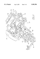
- FIG. 1 is a plan view of a vehicle chassis having a front axle and a pair of rear axles located in tandem combined with a drive train arrangement in accordance with the present invention that is capable of providing six-wheel drive to the vehicle;
- FIG. 2 is a perspective view of the rear part of the drive train arrangement that provides drive to the rear tandem axles;
- FIG. 3 is an enlarged plan view of the rear part of the drive arrangement seen in FIG. 2 with various parts removed so as to more clearly show the drive train arrangement;
- FIG. 4 is an enlarged sectional view taken on line 4--4 of FIG. 2 and shows the gearing located within the transfer case which provides drive to the rear tandem axles;
- FIG. 5 is an enlarged sectional view taken on line 5--5 of FIG. 2 and shows the differential gearing incorporated in the front axle of the rear tandem axles;
- FIG. 6 is a schematic diagram showing the drive train arrangement of FIGS. 1-5 combined with a control system for selectively activating the two transfer cases of the drive train arrangement for providing four-wheel drive and six-wheel drive.
- the chassis 10 of a six-wheel drive vehicle is shown that includes a frame 12 composed of a pair of laterally spaced side rails 14 and 16 supported by a front axle 18 and a pair of rear axles 20 and 22 arranged in tandem.
- the opposed ends of the front axle 18 is provided with a pair of steerable wheels 24 the supporting axle of each of which is connected to the vehicle frame 12 through a leading arm suspension system (not shown).
- Each of the rear axles 20 and 22 similarly has its opposed ends provided with wheels 26 and 28, respectively, and is connected to its associated side rail of the frame 12 by a trailing arm suspension system (not shown).
- the front end of the vehicle frame 12 supports an internal combustion engine 30, the exhaust manifold of which communicates with an exhaust system 32 that has a pair of catalytic converters 34 connected with a muffler 36 mounted to the vehicle frame 12 behind the rear axles 20 and 22.
- the engine 30 is combined with a transmission 38 which, in turn, is drivingly connected to a drive train arrangement made in accordance with the present invention and generally indicated by the reference numeral 40.
- the drive train arrangement 40 is adapted to continuously provide drive to the two rear axles 20 and 22 and selectively provide drive to the front axle 18 so that the vehicle can be operated as a four-wheel drive vehicle or a six-wheel drive vehicle.
- the output shaft (not shown) of the transmission 38 provides drive to an input shaft 42 of a two-speed transfer case 44 made by New Venture Gear of Syracuse, N.Y. and identified as Model NVG 244HD.
- the transfer case 44 is provided with a pair of output shafts 46 and 47, the former of which is connected through a universal joint 48 to a drive shaft 49 that extends forwardly for connection through a universal joint 50 with the differential gearing 51 (seen in FIG. 6) incorporated in the front axle 18.
- the gearing arrangement within the transfer case 44 provides a direct connection to the output shaft 47 and, through an internally housed electrically operated clutch shift system (not shown), and a planetary differential system 52 (FIG. 6) provides for selective connection between the input shaft 42 and the output shaft 46 for directing drive through the drive shaft 49 to the front axle 18.
- the other output shaft 47 of the transfer case 44 is connected through a universal joint 54 to the front end of a drive shaft 56.
- the rear end of the drive shaft 56 extends rearwardly and is connected through a universal joint 58 to an input shaft 60 of a second transfer case 62.
- the transfer case 62 is made by the Spicer Axle Division of Dana Corporation located in Fort Wayne, Ind.
- the transfer case 62 is identified by the Spicer Axle Division as Model TC-44, and includes a pair of output shafts 64 and 66 as best seen in FIGS. 4 and 6.
- the output shaft 64 of the transfer case 62 has its rear end rotatably supported by a bearing 68 which, in turn, is supported in a bearing support 70 rigidly formed with the upper part of a differential housing 72 of the axle 20.
- the output shaft 64 is connected through a universal joint 74 to the front end of a drive shaft 76 the rear end of which is drivingly connected through a universal joint 78 to the input shaft of the differential gearing 79 (shown in FIG. 6) incorporated with the rear axle 22.
- the other output shaft 66 of the transfer case 62 is drivingly connected to the input shaft 80 of the differential gearing 81 of the rear axle 20 which is positioned intermediate or between the front axle 18 and the rear axle 22.
- the center longitudinal axis of the input shaft 80 is axially aligned with the longitudinal center axis of each of the drive shaft 56 (located between transfer cases 44 and 62), the input shaft 60, and the output shaft 66 of the transfer case 62.
- FIGS. 4 and 5 show in detail the interconnection between the gearing of the transfer case 62 and the differential gearing 81 of the intermediate or rear axle 20.
- the housing 82 of the transfer case 62 is bolted by a plurality of circumferentially spaced bolts (one of which only is shown and indicated by reference numeral 84) to the differential housing 72 of the axle 20 so that one of the units can be separated from the other very readily in the event that either requires maintenance, repair, or upgrade.
- seal means is provided between the two units so that lubricating oil in the differential housing 72 of the axle 20 and the lubricating oil in the transfer case 62 are separated from each other.
- the input shaft 60 of the transfer case 62 is connected by a spline connection 86 to a carrier member 88.
- the carrier member 88 rotatably supports a plurality of circumferentially spaced side-by-side planet gears 90 and 92 which form a part of a planetary differential system generally indicated by the reference numeral 93 as seen in FIG. 6.
- One transversely aligned set of planet gears 90 supported by the carrier member 88 mesh with a spur gear 94 fixed with the output shaft 66.
- the sleeve shaft 98 has its rear end fixed with a gear 100 that is drivingly connected to a gear 102 rigid with the front end of the output shaft 64.
- An endless chain 104 is entrained about the gears 100 and 102 and serves as a drive transmitting means between these two gears.
- the gear 102 is fixed with the front end of the output shaft 64 and the latter has its rear end connected to the laterally offset differential gearing of the axle 22 as hereinbefore explained. As seen in FIG.
- the output shaft 66 of the transfer case 62 is fixed through a spline connection 106 with the bevel gear input shaft 80 of the differential gearing 81 which forms a part of the rear axle 20.
- the bevel gear of the input shaft 80 meshes with the crown gear 108 of the differential gearing of the rear axle 20.
- the differential gearing 51, 81, and 79 incorporated in the axles 18, 20 and 22, respectively are similar in construction and conventional in design and operation.
- the planetary differential system 93 of the transfer case 62 serves to split the drive torque 50/50 between the output shafts 64 and 66 to provide full-time four-wheel drive to the vehicle.
- clutch plates 110 are incorporated in the transfer case that are electro-mechanically operated for providing a lock-up through the carrier member 88 of the planet gears 90 and 92 with the gear 100 so that part-time drive can be provided, if desired, when the vehicle is operated off-highway.
- the drive train arrangement 40 will normally be in a four-wheel drive mode. This is accomplished through a rotary switch (not shown) located in the vehicle cab.
- the switch forms a part of an electrical control system 112 shown in block form in FIG. 6 that is electrically connected by lines 114 and 116 to electric actuators (not shown) which serve to activate the clutch systems within transfer cases 44 and 62.
- the transfer case 44 By rotating the switch to a "4 REAR FULL-TIME" position, the transfer case 44 will be electrically conditioned through its clutch system so that only the output shaft 47 is activated and drive is directed through the drive shaft 56 to the input shaft 60 of the second transfer case 62.
- control system 112 causes the clutch plates 110 of the transfer case 62 to be located in the released or disengaged position so that full-time four-wheel drive is realized with the drive torque being split 50/50 to the differential gearing 79 and 81 of the two rear axles 20 and 22.
- the switch is rotated to a position indicated as "6WD FULL-TIME" position. This causes the control system 112 to condition the planetary differential 93 of transfer case 62 so as to continue to provide drive to the tandem axles 20 and 22 and to electrically condition the planetary differential 52 of the transfer case 44 to also provide drive to the differential gearing 51 of the front axle through the output shaft 46 and the drive shaft 49.
- the switch will usually be rotated to a position indicated as "6HI PART-TIME".
- the control system 112 will cause both of the planetary differential systems 52 and 93 of the transfer cases 44 and 62 to be placed in a "lock up” mode so as to have part-time six-wheel drive for improved traction.
- the switch can also be rotated to a "6LO" position at which time the control system 112 causes the planetary differential 52 of the transfer case 44 to be conditioned for a low range to provide a lower speed part-time six-wheel drive for off-highway operation of the vehicle.
- the switch has a neutral position indicated by the letter "N". In this position of the switch and when the transmission 38 is placed in the neutral position, all driving axles are disengaged so that the vehicle can be towed.
- one further advantage in having the differential gearing 81 of the axle 20 centrally located between the wheels 26 and using two transfer cases combined as described above is that sufficient space is provided between the side rails 14 and 16 of the frame 12 to have a fuel tank 118 positioned to one side of the main drive shaft 56. Also, one can have the catalytic converters 34 of the exhaust system located at the other side of the drive shaft 56 along the side rail 14.
Landscapes
- Engineering & Computer Science (AREA)
- Chemical & Material Sciences (AREA)
- Combustion & Propulsion (AREA)
- Transportation (AREA)
- Mechanical Engineering (AREA)
- Arrangement And Driving Of Transmission Devices (AREA)
Abstract
Description
Claims (8)
Priority Applications (1)
| Application Number | Priority Date | Filing Date | Title |
|---|---|---|---|
| US08/931,036 US5950750A (en) | 1997-09-16 | 1997-09-16 | Drive arrangement for a motor vehicle |
Applications Claiming Priority (1)
| Application Number | Priority Date | Filing Date | Title |
|---|---|---|---|
| US08/931,036 US5950750A (en) | 1997-09-16 | 1997-09-16 | Drive arrangement for a motor vehicle |
Publications (1)
| Publication Number | Publication Date |
|---|---|
| US5950750A true US5950750A (en) | 1999-09-14 |
Family
ID=25460130
Family Applications (1)
| Application Number | Title | Priority Date | Filing Date |
|---|---|---|---|
| US08/931,036 Expired - Lifetime US5950750A (en) | 1997-09-16 | 1997-09-16 | Drive arrangement for a motor vehicle |
Country Status (1)
| Country | Link |
|---|---|
| US (1) | US5950750A (en) |
Cited By (60)
| Publication number | Priority date | Publication date | Assignee | Title |
|---|---|---|---|---|
| US6085853A (en) * | 1997-09-10 | 2000-07-11 | Steyr-Daimler-Puch Aktiengesellschaft | Drive system for multi-axle motor vehicle |
| US6461267B1 (en) * | 2001-01-30 | 2002-10-08 | Dana Corporation | Electronically controlled axle assembly |
| US6631773B1 (en) * | 2000-07-05 | 2003-10-14 | Caterpillar S.A.R.L. | Articulated truck for carrying a load through a plurality of work cycles |
| US20040054459A1 (en) * | 2002-09-13 | 2004-03-18 | Brooks Cary Walter | Drive torque transfer scheme |
| US20040089495A1 (en) * | 2000-12-05 | 2004-05-13 | Stuart Strain | Drive train assembly for use in powered vehicles or trailers |
| US20040266579A1 (en) * | 2003-06-30 | 2004-12-30 | Ziech James F. | Tandem axle carrier structural rib |
| US6877573B2 (en) * | 1999-12-21 | 2005-04-12 | Toshiyuki Hasegawa | Multi-wheel-driving vehicle |
| US20050096174A1 (en) * | 2003-10-31 | 2005-05-05 | Ulrich Mair | Differential gear for a vehicle |
| US20050247148A1 (en) * | 2004-05-10 | 2005-11-10 | Steve Slesinski | Output yoke shaft and assembly |
| US20060113125A1 (en) * | 2000-06-08 | 2006-06-01 | Akihiro Ima | Multi-wheel-drive vehicle with a front transaxle device |
| WO2006073401A1 (en) * | 2005-01-07 | 2006-07-13 | Mack Trucks, Inc. | Multiple rear drive axles with common gearing |
| US7096990B2 (en) * | 2001-07-30 | 2006-08-29 | Spicer Technology Inc. | Double disconnect assembly for multi-axle vehicles |
| US20070007053A1 (en) * | 2004-06-22 | 2007-01-11 | Abel Thomas E | Emergency utility vehicle |
| US20080245585A1 (en) * | 2005-06-15 | 2008-10-09 | Volvo Lastvagnar Ab | Vehicle Drive Line |
| US20080308334A1 (en) * | 2007-03-16 | 2008-12-18 | Leonard Joshua J | Vehicle with space utilization |
| US20090000849A1 (en) * | 2007-03-16 | 2009-01-01 | Leonard Joshua J | Method and apparatus related to transportability of a vehicle |
| US20090071737A1 (en) * | 2007-03-16 | 2009-03-19 | Leonard Joshua J | Vehicle |
| US20090071739A1 (en) * | 2007-03-16 | 2009-03-19 | Leonard Joshua J | Utility vehicle having modular components |
| US20090091101A1 (en) * | 2007-03-16 | 2009-04-09 | Leonard Joshua J | Vehicle |
| US20090121518A1 (en) * | 2007-03-16 | 2009-05-14 | Leonard Joshua J | Vehicle with space utilization |
| DE102008052072A1 (en) * | 2008-10-17 | 2010-04-22 | Rheinmetall Landsysteme Gmbh | Motor vehicle with four-wheel drive |
| US20110024222A1 (en) * | 2007-11-08 | 2011-02-03 | Agco Gmbh | Utility vehicle with at least three driveable vehicle axles |
| CN102673394A (en) * | 2012-05-31 | 2012-09-19 | 山西华煤智科机电设备有限公司 | Mining anti-explosion trackless rubber tire vehicle chassis |
| US20130085031A1 (en) * | 2011-09-30 | 2013-04-04 | Arvinmeritor Technology, Llc | Drive Axle Assembly and Disengagement System |
| US8523738B2 (en) | 2011-01-21 | 2013-09-03 | Dana Heavy Vehicle Systems Group, Llc | Method of shifting a tandem drive axle having an inter-axle differential |
| US20130283951A1 (en) * | 2012-04-27 | 2013-10-31 | Zf Friedrichshafen Ag | Axle device for working machines with at least one axle center transmission |
| US20140067219A1 (en) * | 2011-02-18 | 2014-03-06 | Pete Stares | Vehicle and method of controlling a vehicle |
| WO2014037491A1 (en) * | 2012-09-06 | 2014-03-13 | Iveco S.P.A. | Hybrid vehicle comprising a torque distributor |
| US8998253B2 (en) | 2012-03-30 | 2015-04-07 | Polaris Industries Inc. | Folding cab frame |
| WO2015080722A1 (en) | 2013-11-27 | 2015-06-04 | Volvo Truck Corporation | Vehicle with rear drive axle assembly and the ability to neutralize |
| CN104816628A (en) * | 2014-01-31 | 2015-08-05 | 阿文美驰技术有限责任公司 | Drive axle assembly with a collar actuator mechanism |
| US9102232B2 (en) | 2010-07-20 | 2015-08-11 | Dana Heavy Vehicle Systems Group, Llc | Drive axle system having a clutching device |
| CN105128661A (en) * | 2015-08-03 | 2015-12-09 | 徐州重型机械有限公司 | Power drive unit and crane |
| US9592782B2 (en) | 2012-09-20 | 2017-03-14 | Polaris Industries Inc. | Vehicle |
| RU170876U1 (en) * | 2016-06-14 | 2017-05-12 | Роман Иванович Жирный | ALL-TERRAIN VEHICLE 6x6 |
| RU171244U1 (en) * | 2016-06-14 | 2017-05-25 | Роман Иванович Жирный | ALL-TERRAIN VEHICLE 8x8 |
| US9713976B2 (en) | 2015-05-15 | 2017-07-25 | Polaris Industries Inc. | Utility vehicle |
| US9884647B2 (en) | 2015-12-10 | 2018-02-06 | Polaris Industries Inc. | Utility vehicle |
| US10245946B2 (en) | 2015-05-05 | 2019-04-02 | Magna Powertrain Of America, Inc. | Platform heavy duty transfer case |
| US10358029B2 (en) * | 2015-11-02 | 2019-07-23 | Amanda Bent-Bolt Company | Floating differential suspension system |
| US10399401B2 (en) | 2012-09-20 | 2019-09-03 | Polaris Industries Inc. | Vehicle |
| US10486748B2 (en) | 2012-09-20 | 2019-11-26 | Polaris Industries Inc. | Utility vehicle |
| CN111452574A (en) * | 2020-05-09 | 2020-07-28 | 山东岳华能源集团有限公司 | Six-drive transmission device of highway-railway dual-purpose traction locomotive |
| CN111452575A (en) * | 2020-05-14 | 2020-07-28 | 山东岳华能源集团有限公司 | Eight-drive transmission device of highway-railway dual-purpose traction locomotive |
| CN111546882A (en) * | 2020-06-08 | 2020-08-18 | 山东岳华能源集团有限公司 | Road-rail dual-purpose six-wheel-drive traction locomotive and traction method |
| US10793181B2 (en) | 2018-02-13 | 2020-10-06 | Polaris Industries Inc. | All-terrain vehicle |
| US10857880B2 (en) * | 2018-05-01 | 2020-12-08 | Yamaha Hatsudoki Kabushiki Kaisha | Vehicle |
| US10946736B2 (en) | 2018-06-05 | 2021-03-16 | Polaris Industries Inc. | All-terrain vehicle |
| USD937710S1 (en) | 2020-07-24 | 2021-12-07 | Polaris Industries Inc. | All-terrain vehicle |
| US11247562B2 (en) * | 2016-12-14 | 2022-02-15 | Iveco S.P.A. | Power transmission assembly for tandem axles |
| US11285808B2 (en) * | 2017-11-10 | 2022-03-29 | Syn Trac Gmbh | Modular drive train and a vehicle comprising such a drive train |
| US11718240B2 (en) | 2019-12-20 | 2023-08-08 | Polaris Industries Inc. | All-terrain vehicle |
| US20240239185A1 (en) * | 2023-01-12 | 2024-07-18 | Toyota Jidosha Kabushiki Kaisha | Vehicle with exhaust purification device |
| US12172518B2 (en) | 2019-04-30 | 2024-12-24 | Polaris Industries Inc. | Vehicle |
| US12179582B1 (en) * | 2024-03-06 | 2024-12-31 | David Delforte | Low-floor bus support structure |
| US12187127B2 (en) | 2020-05-15 | 2025-01-07 | Polaris Industries Inc. | Off-road vehicle |
| US12385429B2 (en) | 2022-06-13 | 2025-08-12 | Polaris Industries Inc. | Powertrain for a utility vehicle |
| US12384464B2 (en) | 2020-05-15 | 2025-08-12 | Polaris Industries Inc. | Off-road vehicle |
| USD1103845S1 (en) | 2023-01-20 | 2025-12-02 | Polaris Industries Inc. | Grille for an off-road vehicle |
| US12552246B2 (en) | 2023-06-21 | 2026-02-17 | Polaris Industries Inc. | Utility vehicle |
Citations (10)
| Publication number | Priority date | Publication date | Assignee | Title |
|---|---|---|---|---|
| US2158320A (en) * | 1937-10-07 | 1939-05-16 | Yellow Truck & Coach Mfg Co | Power-divided transmission |
| US2267562A (en) * | 1940-09-14 | 1941-12-23 | Four Wheel Drive Auto Company | Center differential for multiple drive vehicles |
| US3083782A (en) * | 1961-09-18 | 1963-04-02 | Fiat Spa | Vehicle with driven front steerable wheels and driven tandem rear wheels |
| US3773130A (en) * | 1969-05-12 | 1973-11-20 | O Mueller | Variable torque transmission |
| US4050534A (en) * | 1975-02-13 | 1977-09-27 | Eaton Corporation | Drive axle system useable in 6 × 6 vehicle |
| US4407387A (en) * | 1981-05-29 | 1983-10-04 | General Motors Corporation | Control system for split axle drive mechanism |
| US4966244A (en) * | 1987-01-30 | 1990-10-30 | Esarco Limited | Vehicle having plural axles and drive system therefor |
| US5363938A (en) * | 1993-03-09 | 1994-11-15 | New Venture Gear, Inc. | Power transfer system for a four-wheel drive vehicle |
| US5400866A (en) * | 1993-03-10 | 1995-03-28 | New Venture Gear, Inc. | Torque modulated transfer case |
| US5411110A (en) * | 1993-03-09 | 1995-05-02 | New Venture Gear, Inc. | Power transfer system for a four-wheel drive vehicle |
-
1997
- 1997-09-16 US US08/931,036 patent/US5950750A/en not_active Expired - Lifetime
Patent Citations (10)
| Publication number | Priority date | Publication date | Assignee | Title |
|---|---|---|---|---|
| US2158320A (en) * | 1937-10-07 | 1939-05-16 | Yellow Truck & Coach Mfg Co | Power-divided transmission |
| US2267562A (en) * | 1940-09-14 | 1941-12-23 | Four Wheel Drive Auto Company | Center differential for multiple drive vehicles |
| US3083782A (en) * | 1961-09-18 | 1963-04-02 | Fiat Spa | Vehicle with driven front steerable wheels and driven tandem rear wheels |
| US3773130A (en) * | 1969-05-12 | 1973-11-20 | O Mueller | Variable torque transmission |
| US4050534A (en) * | 1975-02-13 | 1977-09-27 | Eaton Corporation | Drive axle system useable in 6 × 6 vehicle |
| US4407387A (en) * | 1981-05-29 | 1983-10-04 | General Motors Corporation | Control system for split axle drive mechanism |
| US4966244A (en) * | 1987-01-30 | 1990-10-30 | Esarco Limited | Vehicle having plural axles and drive system therefor |
| US5363938A (en) * | 1993-03-09 | 1994-11-15 | New Venture Gear, Inc. | Power transfer system for a four-wheel drive vehicle |
| US5411110A (en) * | 1993-03-09 | 1995-05-02 | New Venture Gear, Inc. | Power transfer system for a four-wheel drive vehicle |
| US5400866A (en) * | 1993-03-10 | 1995-03-28 | New Venture Gear, Inc. | Torque modulated transfer case |
Non-Patent Citations (4)
| Title |
|---|
| "The Heavy Duty, Over-the-Shoulder Model 70 HD/OS", Dana Corporation, Published, no date indicated. |
| The Heavy Duty, Over the Shoulder Model 70 HD/OS , Dana Corporation, Published, no date indicated. * |
| The Motor Vehicle , Chapter 36. Six Wheel Vehicles , Published date not known. * |
| The Motor Vehicle, Chapter 36. "Six-Wheel Vehicles", Published--date not known. |
Cited By (114)
| Publication number | Priority date | Publication date | Assignee | Title |
|---|---|---|---|---|
| US6085853A (en) * | 1997-09-10 | 2000-07-11 | Steyr-Daimler-Puch Aktiengesellschaft | Drive system for multi-axle motor vehicle |
| US6877573B2 (en) * | 1999-12-21 | 2005-04-12 | Toshiyuki Hasegawa | Multi-wheel-driving vehicle |
| US7168518B2 (en) * | 2000-06-08 | 2007-01-30 | Akihiro Ima | Multi-wheel-drive vehicle with a front transaxle device |
| US20060113125A1 (en) * | 2000-06-08 | 2006-06-01 | Akihiro Ima | Multi-wheel-drive vehicle with a front transaxle device |
| US6631773B1 (en) * | 2000-07-05 | 2003-10-14 | Caterpillar S.A.R.L. | Articulated truck for carrying a load through a plurality of work cycles |
| US20040089495A1 (en) * | 2000-12-05 | 2004-05-13 | Stuart Strain | Drive train assembly for use in powered vehicles or trailers |
| US7093681B2 (en) * | 2000-12-05 | 2006-08-22 | James W. Cooper | Drive train assembly for use in powered vehicles or trailers |
| US6461267B1 (en) * | 2001-01-30 | 2002-10-08 | Dana Corporation | Electronically controlled axle assembly |
| US7096990B2 (en) * | 2001-07-30 | 2006-08-29 | Spicer Technology Inc. | Double disconnect assembly for multi-axle vehicles |
| US20040054459A1 (en) * | 2002-09-13 | 2004-03-18 | Brooks Cary Walter | Drive torque transfer scheme |
| US6810318B2 (en) | 2002-09-13 | 2004-10-26 | General Motors Corporation | Drive torque transfer scheme |
| US20040266579A1 (en) * | 2003-06-30 | 2004-12-30 | Ziech James F. | Tandem axle carrier structural rib |
| US7258644B2 (en) | 2003-06-30 | 2007-08-21 | Dana Corporation | Tandem axle carrier structural rib |
| US20050096174A1 (en) * | 2003-10-31 | 2005-05-05 | Ulrich Mair | Differential gear for a vehicle |
| US7252173B2 (en) * | 2003-10-31 | 2007-08-07 | Zf Friedrichshafen Ag | Differential gear for a vehicle |
| US7690449B2 (en) | 2004-05-10 | 2010-04-06 | Dana Heavy Vehicle Systems Group, Llc | Output yoke shaft and assembly |
| US20050247148A1 (en) * | 2004-05-10 | 2005-11-10 | Steve Slesinski | Output yoke shaft and assembly |
| US20070007053A1 (en) * | 2004-06-22 | 2007-01-11 | Abel Thomas E | Emergency utility vehicle |
| US8215422B2 (en) * | 2004-06-22 | 2012-07-10 | Alternative Support Apparatus, Llc | Emergency utility vehicle |
| WO2006073401A1 (en) * | 2005-01-07 | 2006-07-13 | Mack Trucks, Inc. | Multiple rear drive axles with common gearing |
| US20080245585A1 (en) * | 2005-06-15 | 2008-10-09 | Volvo Lastvagnar Ab | Vehicle Drive Line |
| US7954576B2 (en) * | 2005-06-15 | 2011-06-07 | Volvo Lastvagnar Ab | Vehicle drive line |
| US20090091101A1 (en) * | 2007-03-16 | 2009-04-09 | Leonard Joshua J | Vehicle |
| US8167072B2 (en) | 2007-03-16 | 2012-05-01 | Polaris Industries Inc. | Vehicle with space utilization |
| US20090121518A1 (en) * | 2007-03-16 | 2009-05-14 | Leonard Joshua J | Vehicle with space utilization |
| US20090071739A1 (en) * | 2007-03-16 | 2009-03-19 | Leonard Joshua J | Utility vehicle having modular components |
| US20150197296A1 (en) * | 2007-03-16 | 2015-07-16 | Polaris Industries Inc. | Vehicle |
| US7717495B2 (en) | 2007-03-16 | 2010-05-18 | Polaris Industries, Inc. | Vehicle with space utilization |
| US7795602B2 (en) | 2007-03-16 | 2010-09-14 | Polaris Industries Inc. | Vehicle |
| US7871106B2 (en) | 2007-03-16 | 2011-01-18 | Polaris Industries Inc. | Method and apparatus related to transportability of a vehicle |
| US9004510B2 (en) | 2007-03-16 | 2015-04-14 | Polaris Industries Inc. | Vehicle |
| US20080308334A1 (en) * | 2007-03-16 | 2008-12-18 | Leonard Joshua J | Vehicle with space utilization |
| US20090071737A1 (en) * | 2007-03-16 | 2009-03-19 | Leonard Joshua J | Vehicle |
| US8029021B2 (en) | 2007-03-16 | 2011-10-04 | Polaris Industries Inc. | Vehicle |
| US8132827B2 (en) | 2007-03-16 | 2012-03-13 | Polaris Industries Inc. | Vehicle |
| US10384722B2 (en) | 2007-03-16 | 2019-08-20 | Polaris Industries Inc. | Vehicle |
| US8205910B2 (en) | 2007-03-16 | 2012-06-26 | Polaris Industries Inc. | Utility vehicle having modular components |
| US20090000849A1 (en) * | 2007-03-16 | 2009-01-01 | Leonard Joshua J | Method and apparatus related to transportability of a vehicle |
| US11254372B2 (en) | 2007-03-16 | 2022-02-22 | Polaris Industries Inc. | Vehicle |
| US10960937B2 (en) | 2007-03-16 | 2021-03-30 | Polaris Industries Inc. | Vehicle |
| US20110024222A1 (en) * | 2007-11-08 | 2011-02-03 | Agco Gmbh | Utility vehicle with at least three driveable vehicle axles |
| DE102008052072B4 (en) * | 2008-10-17 | 2011-04-28 | Rheinmetall Landsysteme Gmbh | Motor vehicle with four-wheel drive |
| DE102008052072A1 (en) * | 2008-10-17 | 2010-04-22 | Rheinmetall Landsysteme Gmbh | Motor vehicle with four-wheel drive |
| US9102232B2 (en) | 2010-07-20 | 2015-08-11 | Dana Heavy Vehicle Systems Group, Llc | Drive axle system having a clutching device |
| US9457656B2 (en) | 2010-07-20 | 2016-10-04 | Dana Heavy Vehicle Systems Group, Llc | Drive axle system having a clutching device |
| US9457655B2 (en) * | 2010-07-20 | 2016-10-04 | Dana Heavy Vehicle Systems Group, Llc | Drive axle system having a clutching device |
| US9457657B2 (en) | 2010-07-20 | 2016-10-04 | Dana Heavy Vehicle Systems Group, Llc | Drive axle system having a clutching device |
| US9428050B2 (en) | 2010-07-20 | 2016-08-30 | Dana Heavy Vehicle Systems Group, Llc | Drive axle system having a clutching device |
| US20150375617A1 (en) * | 2010-07-20 | 2015-12-31 | Dana Heavy Vehicle Systems Group, Llc | Drive axle system having a clutching device |
| US8523738B2 (en) | 2011-01-21 | 2013-09-03 | Dana Heavy Vehicle Systems Group, Llc | Method of shifting a tandem drive axle having an inter-axle differential |
| US9346353B2 (en) * | 2011-02-18 | 2016-05-24 | Jaguar Land Rover Limited | Vehicle controller for changing the number of driven wheels |
| US20140067219A1 (en) * | 2011-02-18 | 2014-03-06 | Pete Stares | Vehicle and method of controlling a vehicle |
| US8651994B2 (en) * | 2011-09-30 | 2014-02-18 | Arvinmeritor Technology, Llc | Drive axle assembly and disengagement system |
| US20130085031A1 (en) * | 2011-09-30 | 2013-04-04 | Arvinmeritor Technology, Llc | Drive Axle Assembly and Disengagement System |
| US8998253B2 (en) | 2012-03-30 | 2015-04-07 | Polaris Industries Inc. | Folding cab frame |
| US20130283951A1 (en) * | 2012-04-27 | 2013-10-31 | Zf Friedrichshafen Ag | Axle device for working machines with at least one axle center transmission |
| US9429212B2 (en) * | 2012-04-27 | 2016-08-30 | Zf Friedrichshafen Ag | Axle device for working machines with at least one axle center transmission |
| CN102673394A (en) * | 2012-05-31 | 2012-09-19 | 山西华煤智科机电设备有限公司 | Mining anti-explosion trackless rubber tire vehicle chassis |
| CN102673394B (en) * | 2012-05-31 | 2014-08-06 | 山西华煤智科机电设备有限公司 | Mining anti-explosion trackless rubber tire vehicle chassis |
| US20150258886A1 (en) * | 2012-09-06 | 2015-09-17 | Iveco S.P.A. | Hybrid vehicle comprising a torque distributor |
| US9499049B2 (en) * | 2012-09-06 | 2016-11-22 | Iveco S.P.A. | Hybrid vehicle comprising a torque distributor |
| WO2014037491A1 (en) * | 2012-09-06 | 2014-03-13 | Iveco S.P.A. | Hybrid vehicle comprising a torque distributor |
| US11926190B2 (en) | 2012-09-20 | 2024-03-12 | Polaris Industries Inc. | Vehicle |
| US11235814B2 (en) | 2012-09-20 | 2022-02-01 | Polaris Industries Inc. | Utility vehicle |
| US9592782B2 (en) | 2012-09-20 | 2017-03-14 | Polaris Industries Inc. | Vehicle |
| US11607920B2 (en) | 2012-09-20 | 2023-03-21 | Polaris Industries Inc. | Vehicle |
| US11951794B2 (en) | 2012-09-20 | 2024-04-09 | Polaris Industries Inc. | Vehicle |
| US11787251B2 (en) | 2012-09-20 | 2023-10-17 | Polaris Industries Inc. | Vehicle |
| US11104194B2 (en) | 2012-09-20 | 2021-08-31 | Polaris Industries Inc. | Vehicle |
| US10486748B2 (en) | 2012-09-20 | 2019-11-26 | Polaris Industries Inc. | Utility vehicle |
| US10399401B2 (en) | 2012-09-20 | 2019-09-03 | Polaris Industries Inc. | Vehicle |
| WO2015080722A1 (en) | 2013-11-27 | 2015-06-04 | Volvo Truck Corporation | Vehicle with rear drive axle assembly and the ability to neutralize |
| US10350996B2 (en) | 2013-11-27 | 2019-07-16 | Volvo Truck Corporation | Vehicle with rear drive axle assembly and the ability to neutralize |
| EP3074262A4 (en) * | 2013-11-27 | 2017-06-14 | Volvo Truck Corporation | Vehicle with rear drive axle assembly and the ability to neutralize |
| US9243704B2 (en) * | 2014-01-31 | 2016-01-26 | Arvinmeritor Technology, Llc | Drive axle assembly with a collar actuator mechanism |
| CN104816628A (en) * | 2014-01-31 | 2015-08-05 | 阿文美驰技术有限责任公司 | Drive axle assembly with a collar actuator mechanism |
| US20150219197A1 (en) * | 2014-01-31 | 2015-08-06 | Arvinmeritor Technology, Llc | Drive Axle Assembly with a Collar Actuator Mechanism |
| US10245946B2 (en) | 2015-05-05 | 2019-04-02 | Magna Powertrain Of America, Inc. | Platform heavy duty transfer case |
| US9713976B2 (en) | 2015-05-15 | 2017-07-25 | Polaris Industries Inc. | Utility vehicle |
| US11752860B2 (en) | 2015-05-15 | 2023-09-12 | Polaris Industries Inc. | Utility vehicle |
| CN105128661B (en) * | 2015-08-03 | 2019-10-22 | 徐州重型机械有限公司 | A kind of power drive unit and crane |
| CN105128661A (en) * | 2015-08-03 | 2015-12-09 | 徐州重型机械有限公司 | Power drive unit and crane |
| US10358029B2 (en) * | 2015-11-02 | 2019-07-23 | Amanda Bent-Bolt Company | Floating differential suspension system |
| US10703199B2 (en) | 2015-11-02 | 2020-07-07 | Amanda Bent-Bolt Company | Floating differential suspension system |
| US9884647B2 (en) | 2015-12-10 | 2018-02-06 | Polaris Industries Inc. | Utility vehicle |
| US10926799B2 (en) | 2015-12-10 | 2021-02-23 | Polaris Industries Inc. | Utility vehicle |
| US10766533B2 (en) | 2015-12-10 | 2020-09-08 | Polaris Industries Inc. | Utility vehicle |
| RU170876U1 (en) * | 2016-06-14 | 2017-05-12 | Роман Иванович Жирный | ALL-TERRAIN VEHICLE 6x6 |
| RU171244U1 (en) * | 2016-06-14 | 2017-05-25 | Роман Иванович Жирный | ALL-TERRAIN VEHICLE 8x8 |
| US11247562B2 (en) * | 2016-12-14 | 2022-02-15 | Iveco S.P.A. | Power transmission assembly for tandem axles |
| US11285808B2 (en) * | 2017-11-10 | 2022-03-29 | Syn Trac Gmbh | Modular drive train and a vehicle comprising such a drive train |
| US12409882B2 (en) | 2018-02-13 | 2025-09-09 | Polaris Industries Inc. | All-terrain vehicle |
| US10793181B2 (en) | 2018-02-13 | 2020-10-06 | Polaris Industries Inc. | All-terrain vehicle |
| US10857880B2 (en) * | 2018-05-01 | 2020-12-08 | Yamaha Hatsudoki Kabushiki Kaisha | Vehicle |
| US10946736B2 (en) | 2018-06-05 | 2021-03-16 | Polaris Industries Inc. | All-terrain vehicle |
| US12172518B2 (en) | 2019-04-30 | 2024-12-24 | Polaris Industries Inc. | Vehicle |
| US12403841B2 (en) | 2019-12-20 | 2025-09-02 | Polaris Industries Inc. | All-terrain vehicle |
| US12296791B2 (en) | 2019-12-20 | 2025-05-13 | Polaris Industries Inc. | All-terrain vehicle |
| US11718240B2 (en) | 2019-12-20 | 2023-08-08 | Polaris Industries Inc. | All-terrain vehicle |
| CN111452574A (en) * | 2020-05-09 | 2020-07-28 | 山东岳华能源集团有限公司 | Six-drive transmission device of highway-railway dual-purpose traction locomotive |
| CN111452575A (en) * | 2020-05-14 | 2020-07-28 | 山东岳华能源集团有限公司 | Eight-drive transmission device of highway-railway dual-purpose traction locomotive |
| US12337690B2 (en) | 2020-05-15 | 2025-06-24 | Polaris Industries Inc. | Off-road vehicle |
| US12187127B2 (en) | 2020-05-15 | 2025-01-07 | Polaris Industries Inc. | Off-road vehicle |
| US12384464B2 (en) | 2020-05-15 | 2025-08-12 | Polaris Industries Inc. | Off-road vehicle |
| CN111546882A (en) * | 2020-06-08 | 2020-08-18 | 山东岳华能源集团有限公司 | Road-rail dual-purpose six-wheel-drive traction locomotive and traction method |
| USD937710S1 (en) | 2020-07-24 | 2021-12-07 | Polaris Industries Inc. | All-terrain vehicle |
| USD962823S1 (en) | 2020-07-24 | 2022-09-06 | Polaris Industries Inc. | Combination center and side lamps for all-terrain vehicle |
| USD958006S1 (en) | 2020-07-24 | 2022-07-19 | Polaris Industries Inc. | All-terrain vehicle |
| US12385429B2 (en) | 2022-06-13 | 2025-08-12 | Polaris Industries Inc. | Powertrain for a utility vehicle |
| US20240239185A1 (en) * | 2023-01-12 | 2024-07-18 | Toyota Jidosha Kabushiki Kaisha | Vehicle with exhaust purification device |
| US12496898B2 (en) * | 2023-01-12 | 2025-12-16 | Toyota Jidosha Kabushiki Kaisha | Vehicle with exhaust purification device |
| USD1103845S1 (en) | 2023-01-20 | 2025-12-02 | Polaris Industries Inc. | Grille for an off-road vehicle |
| US12552246B2 (en) | 2023-06-21 | 2026-02-17 | Polaris Industries Inc. | Utility vehicle |
| US12179582B1 (en) * | 2024-03-06 | 2024-12-31 | David Delforte | Low-floor bus support structure |
Similar Documents
| Publication | Publication Date | Title |
|---|---|---|
| US5950750A (en) | Drive arrangement for a motor vehicle | |
| USRE32565E (en) | Four-wheel vehicle drive system | |
| EP0072990B1 (en) | Four-wheel vehicle drive system | |
| US6821166B2 (en) | Power train | |
| US2290089A (en) | Four wheel drive | |
| US5078229A (en) | Four-wheel-drive motor vehicle of transversely-disposed engine type | |
| JP3040860B2 (en) | Midship 4-wheel drive horizontal transmission | |
| US5205373A (en) | Structure of vehicle power train | |
| US7770483B2 (en) | Power train for an amphibious vehicle | |
| AU2001282320A1 (en) | Power train | |
| KR20070015360A (en) | Motorized drive system for vehicles with skid steering | |
| US5380255A (en) | Transfer case for part time front wheel drive in a four wheel drive motor vehicle | |
| US4511012A (en) | Drive axle for a motor vehicle | |
| US4745986A (en) | Motor vehicle with front-mounted transverse power unit | |
| US4450734A (en) | Transmission apparatus for a four-wheel drive motor vehicle | |
| EP0096904B1 (en) | Differential assembly for distribution of torque between the front and rear axles of an automotive vehicle | |
| EP0186123A2 (en) | Vehicle drive system | |
| JPH0311925B2 (en) | ||
| US20070272453A1 (en) | Power Plant and Driveline for Vehicles | |
| EP4238802B1 (en) | Improved torque distributor system among axles of a heavy vehicle | |
| JPS59176120A (en) | Power transmission device for car | |
| JP3173871B2 (en) | Power transmission device for four-wheel drive vehicles | |
| JPS6313822A (en) | Transfer device for four-wheel drive vehicle | |
| JPS635293B2 (en) | ||
| JP2802309B2 (en) | Power distribution control device for four-wheel drive vehicle |
Legal Events
| Date | Code | Title | Description |
|---|---|---|---|
| AS | Assignment |
Owner name: CHRYSLER CORPORATION, MICHIGAN Free format text: ASSIGNMENT OF ASSIGNORS INTEREST;ASSIGNORS:DONG, LEONG C.;ROSENTHAL, NICHOLAS;JUNIS, MARK W.;AND OTHERS;REEL/FRAME:008716/0587 Effective date: 19970902 |
|
| STCF | Information on status: patent grant |
Free format text: PATENTED CASE |
|
| FPAY | Fee payment |
Year of fee payment: 4 |
|
| FPAY | Fee payment |
Year of fee payment: 8 |
|
| AS | Assignment |
Owner name: WILMINGTON TRUST COMPANY, DELAWARE Free format text: GRANT OF SECURITY INTEREST IN PATENT RIGHTS - FIRST PRIORITY;ASSIGNOR:CHRYSLER LLC;REEL/FRAME:019773/0001 Effective date: 20070803 Owner name: WILMINGTON TRUST COMPANY,DELAWARE Free format text: GRANT OF SECURITY INTEREST IN PATENT RIGHTS - FIRST PRIORITY;ASSIGNOR:CHRYSLER LLC;REEL/FRAME:019773/0001 Effective date: 20070803 |
|
| AS | Assignment |
Owner name: WILMINGTON TRUST COMPANY, DELAWARE Free format text: GRANT OF SECURITY INTEREST IN PATENT RIGHTS - SECOND PRIORITY;ASSIGNOR:CHRYSLER LLC;REEL/FRAME:019767/0810 Effective date: 20070803 Owner name: WILMINGTON TRUST COMPANY,DELAWARE Free format text: GRANT OF SECURITY INTEREST IN PATENT RIGHTS - SECOND PRIORITY;ASSIGNOR:CHRYSLER LLC;REEL/FRAME:019767/0810 Effective date: 20070803 |
|
| AS | Assignment |
Owner name: DAIMLERCHRYSLER CORPORATION, MICHIGAN Free format text: CHANGE OF NAME;ASSIGNOR:CHRYSLER CORPORATION;REEL/FRAME:021826/0034 Effective date: 19981116 |
|
| AS | Assignment |
Owner name: CHRYSLER LLC, MICHIGAN Free format text: CHANGE OF NAME;ASSIGNOR:DAIMLERCHRYSLER COMPANY LLC;REEL/FRAME:021832/0233 Effective date: 20070727 Owner name: DAIMLERCHRYSLER COMPANY LLC, MICHIGAN Free format text: CHANGE OF NAME;ASSIGNOR:DAIMLERCHRYSLER CORPORATION;REEL/FRAME:021832/0256 Effective date: 20070329 |
|
| AS | Assignment |
Owner name: US DEPARTMENT OF THE TREASURY, DISTRICT OF COLUMBI Free format text: GRANT OF SECURITY INTEREST IN PATENT RIGHTS - THIR;ASSIGNOR:CHRYSLER LLC;REEL/FRAME:022259/0188 Effective date: 20090102 Owner name: US DEPARTMENT OF THE TREASURY,DISTRICT OF COLUMBIA Free format text: GRANT OF SECURITY INTEREST IN PATENT RIGHTS - THIR;ASSIGNOR:CHRYSLER LLC;REEL/FRAME:022259/0188 Effective date: 20090102 Owner name: US DEPARTMENT OF THE TREASURY, DISTRICT OF COLUMBIA Free format text: GRANT OF SECURITY INTEREST IN PATENT RIGHTS - THIR;ASSIGNOR:CHRYSLER LLC;REEL/FRAME:022259/0188 Effective date: 20090102 |
|
| AS | Assignment |
Owner name: CHRYSLER LLC, MICHIGAN Free format text: RELEASE BY SECURED PARTY;ASSIGNOR:US DEPARTMENT OF THE TREASURY;REEL/FRAME:022910/0273 Effective date: 20090608 |
|
| AS | Assignment |
Owner name: CHRYSLER LLC, MICHIGAN Free format text: RELEASE OF SECURITY INTEREST IN PATENT RIGHTS - FIRST PRIORITY;ASSIGNOR:WILMINGTON TRUST COMPANY;REEL/FRAME:022910/0498 Effective date: 20090604 Owner name: CHRYSLER LLC, MICHIGAN Free format text: RELEASE OF SECURITY INTEREST IN PATENT RIGHTS - SECOND PRIORITY;ASSIGNOR:WILMINGTON TRUST COMPANY;REEL/FRAME:022910/0740 Effective date: 20090604 Owner name: NEW CARCO ACQUISITION LLC, MICHIGAN Free format text: ASSIGNMENT OF ASSIGNORS INTEREST;ASSIGNOR:CHRYSLER LLC;REEL/FRAME:022915/0001 Effective date: 20090610 Owner name: THE UNITED STATES DEPARTMENT OF THE TREASURY, DIST Free format text: SECURITY AGREEMENT;ASSIGNOR:NEW CARCO ACQUISITION LLC;REEL/FRAME:022915/0489 Effective date: 20090610 Owner name: CHRYSLER LLC,MICHIGAN Free format text: RELEASE OF SECURITY INTEREST IN PATENT RIGHTS - FIRST PRIORITY;ASSIGNOR:WILMINGTON TRUST COMPANY;REEL/FRAME:022910/0498 Effective date: 20090604 Owner name: CHRYSLER LLC,MICHIGAN Free format text: RELEASE OF SECURITY INTEREST IN PATENT RIGHTS - SECOND PRIORITY;ASSIGNOR:WILMINGTON TRUST COMPANY;REEL/FRAME:022910/0740 Effective date: 20090604 Owner name: NEW CARCO ACQUISITION LLC,MICHIGAN Free format text: ASSIGNMENT OF ASSIGNORS INTEREST;ASSIGNOR:CHRYSLER LLC;REEL/FRAME:022915/0001 Effective date: 20090610 Owner name: THE UNITED STATES DEPARTMENT OF THE TREASURY,DISTR Free format text: SECURITY AGREEMENT;ASSIGNOR:NEW CARCO ACQUISITION LLC;REEL/FRAME:022915/0489 Effective date: 20090610 Owner name: THE UNITED STATES DEPARTMENT OF THE TREASURY, DISTRICT OF COLUMBIA Free format text: SECURITY AGREEMENT;ASSIGNOR:NEW CARCO ACQUISITION LLC;REEL/FRAME:022915/0489 Effective date: 20090610 |
|
| AS | Assignment |
Owner name: CHRYSLER GROUP LLC, MICHIGAN Free format text: CHANGE OF NAME;ASSIGNOR:NEW CARCO ACQUISITION LLC;REEL/FRAME:022919/0126 Effective date: 20090610 Owner name: CHRYSLER GROUP LLC,MICHIGAN Free format text: CHANGE OF NAME;ASSIGNOR:NEW CARCO ACQUISITION LLC;REEL/FRAME:022919/0126 Effective date: 20090610 |
|
| FPAY | Fee payment |
Year of fee payment: 12 |
|
| AS | Assignment |
Owner name: CHRYSLER GROUP LLC, MICHIGAN Free format text: RELEASE BY SECURED PARTY;ASSIGNOR:THE UNITED STATES DEPARTMENT OF THE TREASURY;REEL/FRAME:026343/0298 Effective date: 20110524 Owner name: CHRYSLER GROUP GLOBAL ELECTRIC MOTORCARS LLC, NORT Free format text: RELEASE BY SECURED PARTY;ASSIGNOR:THE UNITED STATES DEPARTMENT OF THE TREASURY;REEL/FRAME:026343/0298 Effective date: 20110524 Owner name: CHRYSLER GROUP GLOBAL ELECTRIC MOTORCARS LLC, NORTH DAKOTA Free format text: RELEASE BY SECURED PARTY;ASSIGNOR:THE UNITED STATES DEPARTMENT OF THE TREASURY;REEL/FRAME:026343/0298 Effective date: 20110524 |
|
| AS | Assignment |
Owner name: CITIBANK, N.A., NEW YORK Free format text: SECURITY AGREEMENT;ASSIGNOR:CHRYSLER GROUP LLC;REEL/FRAME:026404/0123 Effective date: 20110524 |
|
| AS | Assignment |
Owner name: CITIBANK, N.A., NEW YORK Free format text: SECURITY AGREEMENT;ASSIGNOR:CHRYSLER GROUP LLC;REEL/FRAME:026435/0652 Effective date: 20110524 |
|
| AS | Assignment |
Owner name: JPMORGAN CHASE BANK, N.A., ILLINOIS Free format text: SECURITY AGREEMENT;ASSIGNOR:CHRYSLER GROUP LLC;REEL/FRAME:032384/0640 Effective date: 20140207 |
|
| AS | Assignment |
Owner name: FCA US LLC, MICHIGAN Free format text: CHANGE OF NAME;ASSIGNOR:CHRYSLER GROUP LLC;REEL/FRAME:035553/0356 Effective date: 20141203 |
|
| AS | Assignment |
Owner name: FCA US LLC, FORMERLY KNOWN AS CHRYSLER GROUP LLC, MICHIGAN Free format text: RELEASE OF SECURITY INTEREST RELEASING SECOND-LIEN SECURITY INTEREST PREVIOUSLY RECORDED AT REEL 026426 AND FRAME 0644, REEL 026435 AND FRAME 0652, AND REEL 032384 AND FRAME 0591;ASSIGNOR:CITIBANK, N.A.;REEL/FRAME:037784/0001 Effective date: 20151221 Owner name: FCA US LLC, FORMERLY KNOWN AS CHRYSLER GROUP LLC, Free format text: RELEASE OF SECURITY INTEREST RELEASING SECOND-LIEN SECURITY INTEREST PREVIOUSLY RECORDED AT REEL 026426 AND FRAME 0644, REEL 026435 AND FRAME 0652, AND REEL 032384 AND FRAME 0591;ASSIGNOR:CITIBANK, N.A.;REEL/FRAME:037784/0001 Effective date: 20151221 |
|
| AS | Assignment |
Owner name: FCA US LLC (FORMERLY KNOWN AS CHRYSLER GROUP LLC), Free format text: RELEASE BY SECURED PARTY;ASSIGNOR:CITIBANK, N.A.;REEL/FRAME:042885/0255 Effective date: 20170224 Owner name: FCA US LLC (FORMERLY KNOWN AS CHRYSLER GROUP LLC), MICHIGAN Free format text: RELEASE BY SECURED PARTY;ASSIGNOR:CITIBANK, N.A.;REEL/FRAME:042885/0255 Effective date: 20170224 |
|
| AS | Assignment |
Owner name: FCA US LLC (FORMERLY KNOWN AS CHRYSLER GROUP LLC), Free format text: RELEASE BY SECURED PARTY;ASSIGNOR:JPMORGAN CHASE BANK, N.A.;REEL/FRAME:048177/0356 Effective date: 20181113 Owner name: FCA US LLC (FORMERLY KNOWN AS CHRYSLER GROUP LLC), MICHIGAN Free format text: RELEASE BY SECURED PARTY;ASSIGNOR:JPMORGAN CHASE BANK, N.A.;REEL/FRAME:048177/0356 Effective date: 20181113 |