US5944388A - Removable vehicle seat - Google Patents
Removable vehicle seat Download PDFInfo
- Publication number
- US5944388A US5944388A US08/865,459 US86545997A US5944388A US 5944388 A US5944388 A US 5944388A US 86545997 A US86545997 A US 86545997A US 5944388 A US5944388 A US 5944388A
- Authority
- US
- United States
- Prior art keywords
- locking
- seat
- seat base
- vehicle seat
- locking plate
- Prior art date
- Legal status (The legal status is an assumption and is not a legal conclusion. Google has not performed a legal analysis and makes no representation as to the accuracy of the status listed.)
- Expired - Fee Related
Links
Images


Classifications
-
- B—PERFORMING OPERATIONS; TRANSPORTING
- B60—VEHICLES IN GENERAL
- B60N—SEATS SPECIALLY ADAPTED FOR VEHICLES; VEHICLE PASSENGER ACCOMMODATION NOT OTHERWISE PROVIDED FOR
- B60N2/00—Seats specially adapted for vehicles; Arrangement or mounting of seats in vehicles
- B60N2/005—Arrangement or mounting of seats in vehicles, e.g. dismountable auxiliary seats
- B60N2/015—Attaching seats directly to vehicle chassis
- B60N2/01508—Attaching seats directly to vehicle chassis using quick release attachments
- B60N2/01591—Attaching seats directly to vehicle chassis using quick release attachments with wheels coupled to the seat
-
- B—PERFORMING OPERATIONS; TRANSPORTING
- B60—VEHICLES IN GENERAL
- B60N—SEATS SPECIALLY ADAPTED FOR VEHICLES; VEHICLE PASSENGER ACCOMMODATION NOT OTHERWISE PROVIDED FOR
- B60N2/00—Seats specially adapted for vehicles; Arrangement or mounting of seats in vehicles
- B60N2/005—Arrangement or mounting of seats in vehicles, e.g. dismountable auxiliary seats
- B60N2/015—Attaching seats directly to vehicle chassis
- B60N2/01508—Attaching seats directly to vehicle chassis using quick release attachments
- B60N2/01516—Attaching seats directly to vehicle chassis using quick release attachments with locking mechanisms
- B60N2/01583—Attaching seats directly to vehicle chassis using quick release attachments with locking mechanisms locking on transversal elements on the vehicle floor or rail, e.g. transversal rods
Definitions
- This invention relates generally to vehicle seats and specifically to a removable vehicle seat which allows for quick removal and reattachment of the vehicle seat to a vehicle floor.
- the removable vehicle seat includes a seat base which provides a stable structure and allows for the removal and reattachment of the vehicle seat by a single person.
- Removable seats in vehicles have long been utilized to meet a variety of needs.
- removable vehicle seats have been found to be particularly useful for vehicles utilized by disabled persons.
- the ability to easily remove driver and passenger seats to create additional room for entry and departure in and out of a vehicle is crucial in utilizing a vehicle for physically disabled persons, particularly persons confined to wheelchairs.
- Proposed removable vehicle seats have included designs wherein the vehicle seat is fastened to the vehicle floor by utilizing bolts or screws to fasten the seat base to the vehicle floor. While such removable vehicle seat designs securely fasten the vehicle seat to the vehicle floor, they are not practical for use with vehicles for disabled persons in that removal and reattachment of the vehicle seat from the vehicle floor requires bolting and unbolting the seat base to the vehicle floor, a process which is time consuming and difficult.
- a removable vehicle seat which allows for efficient and easy removal and reinstallation of the vehicle seat to and from a vehicle floor.
- the removable vehicle seat of the present invention is removed by simple manipulation of a release bar and sliding the seat base outward from locking plates attached to the vehicle floor.
- the removable vehicle seat has wheels which facilitates easy removal of the vehicle seat from the vehicle.
- the removable vehicle seat of the present invention includes a seat base comprising a housing to which a vehicle seat is permanently attached. Inside the housing is a locking mechanism for attaching the seat base to locking plates affixed to the vehicle floor. The locking plates are affixed to the vehicle floor and serve as a base for receiving the seat base. Inside the seat base is a locking mechanism comprising a lever arm which controls a locking pin for releasably locking the seat base to the locking plates. Extending from the bottom of the seat base are anchor bolts which serve as an additional attachment mechanism to slidably fasten the seat base to the locking plates.
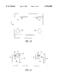
- FIG. 1 is a side view of a seat base with a vehicle seat attached with the seat base fastened to locking plates in the locked position;
- FIG. 2 is a side view of the seat base without a vehicle seat showing the seat base in the locked position
- FIG. 3 is a side view of the seat base showing the seat base in the unlocked position
- FIG. 4 is a perspective view of one embodiment of the locking plates
- FIG. 4A is a top view of one embodiment of a recess formed within the locking plate
- FIG. 5 is perspective view of an alternate embodiment of the locking plates
- FIG. 6 is a perspective view of another embodiment of the locking plates
- FIG. 7 is a diagrammatic representation of a top view of the vehicle seat base oriented in relation to the locking plates so that the locking plates are in a perpendicular configuration to the lever arm;
- FIG. 8 is a diagrammatic representation of a top view of the vehicle seat base oriented in relation to the locking plates so that the locking plates are parallel to the lever arm;
- FIG. 9 is a frontal view of the seat base in the locked position with a bench seat attached to the seat base;
- FIG. 10 is a frontal view of a foldable seat bench in the seating position
- FIG. 11 is a frontal view of a foldable seat bench in the stowed position
- FIG. 11A is a side view along line 4--4 of the bracket and cross-bar;
- FIG. 12 is a top view of an alternate embodiment of a locking plate for receiving a foldable vehicle bench seat
- FIG. 13 is a top view of an alternate embodiment of the locking plates
- FIG. 14 is a top view of multiple locking plates demonstrating alternate arrangements of the locking plates in relation to one another;
- FIG. 15 is a top view of the locking plates showing multiple recesses formed in the locking plates to accommodate variously sized seat bases;
- FIG. 16 is a top view of the smaller locking plates showing multiple recesses formed therein.
- FIG. 17 is a top view showing the recesses reversed in the opposite direction from the previously disclosed locking plates.
- the seat base 2 comprises a housing defining a partial enclosure with a top surface 4 comprised of a top plate 84 to which a vehicle seat 100 may attach.
- the vehicle seat attaches to the top of the seat base 2 and is generally affixed to the top plate 84 by bolting the vehicle seat to the top surface 4.
- the seat base 2 has a front surface 5 and a rear surface 6 with an opening 8 (not shown) in the rear surface 6 through which lever arm 22 extends.
- the seat base 2 has side surfaces 9 and 11 as shown in FIGS. 7-8.
- the bottom 7 of seat base 2 has a first and second end 10 and 12 which attach to locking plates 50 and 52 respectively.
- middle portion 14 which is raised above the ground surface between the first and second ends 10 and 12.
- first and second supporting plates 86 and 88 Extending between the bottom 7 and top 4 of seat base 2 and extending substantially vertically between the first and second ends 10 and 12 to the top surface 4 of the seat base 2, are first and second supporting plates 86 and 88.
- First and second supporting plates 86 and 88 provide structural support for the seat base 2 and act to divide the interior of seat base 2 into three sections comprising the first end portion 10, the middle section 14 and the second end portion 12. Both supporting plates 86 and 88 have an opening formed within the plates near the top 4 of the seat base 2 to allow lever arm 22 to extend through the interior of the housing.
- FIGS. 2 and 3 show seat base 2 without a vehicle seat attached.
- locking mechanism 16 which comprises lever arm 22, linking arms 26, rotating shaft 28, rotating bracket 30, locking pin 36 and spring mechanisms 40 and 58.
- locking plates 50 and 52 are secured to the vehicle floor by either bolting the outer edges 94 and 96 to the vehicle floor or welding the plates to the vehicle floor.
- Locking plates 50 and 52 have a raised middle section 92 with recesses 60 and 62 formed at each end of the locking plates 50 and 52.
- the recesses 60 and 62 are formed to receive the locking pin 36 and anchor bolts 72 and 74 of the seat base 2 which is described in greater detail below.
- lever arm 22 is used to lock and unlock the seat base 2 from the locking plates 50 and 52.
- Lever arm 22, as shown in FIG. 3, extends through the center of the seat base 2 and generally parallel relative to the locking plates 50 and 52.
- Lever arm 22 is preferably equidistant between side surfaces 9 and 11 (see FIG. 7) and extends outward from the rear surface 6 through opening 8 (not shown) of the seat base 2 as shown in FIG. 1.
- lever arm 22 has a first end 20 and a handle end 24.
- the lever arm 22 pivots, moving from an inward position (FIG. 2) to an extended position (FIG. 3), which in turn moves the locking pin 36 from a locked position (FIG. 2) to an unlocked position (FIG. 3).
- the handle end 24 of lever arm 22 is used for grasping the lever arm 22 when moving from the inward to the extended position when locking and unlocking the locking pin 36.
- recess 46 Proximate to the handle end 24 of lever arm 22 is recess 46, which is formed as an aperture in lever arm 22. Recess 46 is configured to receive the rear surface 6 of the seat base 2 adjacent to opening 8. By attaching recess 46 to the rear surface 6 of the seat base 2, the lever arm 22 is locked while in the extended position (FIG. 3).
- linking arms 26 pivotally linked to lever arm 22 at its first end 20 are a pair of linking arms 26, which have an upper end 66 and a lower end (FIG. 3).
- Each linking arm 26 is coupled at its upper end 66 to lever arm 22 by linking bolt 64.
- Both linking arms 26 and the first end 20 of lever arm 22 each have an opening formed therein through which linking bolt 64 extends.
- Linking bolt 64 allows the lever arm 22 and linking arms 26 to pivot with respect to one another when lever arm 22 moves in the horizontal direction from the inward to the extended position. This is illustrated by examining the transition of the relative positions of lever arm 22 and linking arm 26 in FIGS. 2 and 3.
- Each linking arm 26 is linked to lever arm 22 between side surfaces 9 and 11 as is shown in FIGS. 7-8.
- the junction of the linking arms 26 and lever arm 22 is far displaced from either of the locking pins 36.
- the lever arm 22 can be moved back and forth in the horizontal direction, that is, between an inward (FIG. 2) to an extended position (FIG. 3).
- Lever arm 22 can also be moved by an automated means (not disclosed).
- each linking arm 26 pivots about bolt 64 which turns rotating shaft 28 (FIGS. 7-8) clockwise when lever arm 22 moves from an inward to an extended position and counterclockwise when lever arm 22 moves from an extended to an inward position.
- rotating shaft 28 could be divided into two halves with the division occurring at linking arms 26.
- Rotating shaft 28 is fixed at its ends to the first end 34 of rotating bracket 30 (FIG. 2).
- the second end 38 of rotating bracket 30 pivots up and down in relation to the top and bottom of the seat base 2.
- locking pin 36 With the vertical pivoting of rotating bracket 30, which is pivotally coupled to locking pin 36, locking pin 36 moves from a locked position (FIG. 2) to an unlocked position (FIG. 3) releasably fastening seat base 2 to locking plate 50.
- FIGS. 7 and 8 there are two locking pins 36 located at the far right and far left side of the first end 10 of seat base 2. In one embodiment (not shown), there can be four locking pins 36 in one seat base 2 with two locking pins located at each end 10 and 12 of seat base 2.
- locking pin 36 has a lower end 42 which engages the locking end 97 of recess 60 of locking plate 50.
- locking pin 36 has an upper end 44.
- the locking pin recess is comprised of a locking end 97 formed within the surface of locking plates 50 and 52 to receive the lower end 42 of the locking pin 36 while it is in the locked position.
- the lower end 42 of the locking pin 36 may either be rounded (FIG. 2) or pointed (FIG. 3) depending on preference. However, it has been found that the rounded lower end provides for a more stable design.
- collar 54 Approximately half-way between the lower end 42 and the upper end 44 of the locking pin 36 is collar 54.
- Collar 54 is rigidly affixed to the locking pin 36 so as to form a permanent part of the locking pin 36. Thus collar 54 does not move in relation to the locking pin 36 but moves as part of locking pin 36.
- Pivotally attached to collar 54 is the second end 38 of rotating bracket 30.
- Rotating bracket 30 is attached to collar 54 by bolt 56 which allows the upper end 38 of rotating bracket 30 to pivot in relation to collar 54.
- Rotating bracket 30 has an opening formed through its surface for receiving bolt 56 which couples bracket 30 to pivoting pin 36.
- Rotating bracket 30 pivots around rotating shaft 28 with its second end 38 moving in the vertical direction when the lever arm 22 is moved between the inward and extended positions. This movement in turn causes locking pin 36 to move in the vertical direction between the locked and the unlocked positions (FIGS. 2-3).
- Supporting bracket 70 has a first end 76 welded or bolted to the housing which attaches the supporting bracket 70 to the first supporting plate 86. Extending horizontally outward from the first end 76 of the supporting bracket 70 is the second end 78 of supporting bracket 70.
- the second end 78 of supporting bracket 70 has an opening (not shown) formed within the bracket for receiving the upper end 44 of locking pin 36. The opening allows the upper end 44 of the locking pin 36 to move up and down through the opening when moving between the locked and the unlocked positions.
- the locking pin 36 remains in the locked position as shown in FIG. 2 unless lever arm 22 is moved to the extended position (FIG. 3).
- Two spring mechanisms maintain the locking pins 36 in the locked position unless the lever arm 22 is moved to the extended position.
- First spring mechanism 40 is positioned around the locking pin 36 between the second end 78 of bracket 70 and collar 54 (FIG. 2). The tension of the first spring mechanism 40 exerts a constant downward force on the collar 54 and locking pin 36 forcing the locking pin 36 into the locked position.
- Second spring mechanism 58 maintains the lever arm 22 in the inward position. Located along the length of lever arm 22 is opening 90 to which one end of second spring mechanism 58 attaches. Second spring mechanism 58 extends between the opening 90 to the first supporting plate 86 where the spring mechanism 58 attaches to a ring 122, shaped as a semi-circle, extending outward from the surface of the first supporting plate 86 into middle section 14 of the housing of seat base 2.
- Spring mechanism 58 maintains a constant tension on lever arm 22 maintaining lever arm 22 in the inward position. Together, first spring mechanism 40 and second spring mechanism 58 maintains locking pins 36 in the locked position. Thus, when lever arm 22 is pulled from the inward position to the extended position, the tension of first spring mechanism 40 and second spring mechanism 58 resists and forces lever arm 22 and locking pin 36 to the locked position.
- a handle recess 46 is formed near the handle end 24 of the lever arm 22 for fastening the lever arm 22 to the rear surface 6 of the seat base 2 where opening 8 is formed. As shown in FIG. 3, the handle recess 46 is configured to receive the rear surface 6 of the seat base 2 so that when lever arm 22 is fastened to the rear surface 6, it maintains the lever arm 22 in the unlocked position.
- Locking plates 50 and 52 are affixed to the vehicle floor (F) either by bolting or welding the locking plates 50 and 52 to the floor (F) (not shown). As illustrated in FIG. 4, the locking plates have a raised middle section 92 through which recesses 60 and 62 are formed and lowered side sections 94 and 96. When attaching the locking plates 50 and 52 to the vehicle floor F, side sections 94 and 96 are either bolted or welded to the vehicle floor (F) leaving middle section 92 slightly raised above the surface of vehicle floor (F).
- the first and second ends 10 and 12 of the seat base 2 each have a pair of anchor bolts 74 and 72 affixed to the bottom surface 7, which extend through front and rear bushings 128 and 130 of first and second ends 10 and 12.
- Extending from the bottom surface of the first end 10 are front anchor bolts 74 and extending from the bottom surface of the second end 12 are rear anchor bolts 72.
- the anchor bolts 72 and 74 are threaded and screwed through nut 110 which are welded to the bottom 7 of the interior of the seat base 2. The fact that the anchor bolts 72 and 74 are threaded allows the distance between the seat base 2 and the locking plates to be adjusted by turning the anchor bolts 72 and 74.
- the anchor bolts extend from the bottom 7 of the seat base 2 so that the head 104 of the bolt extends downward with the curved portion of the head 104 facing towards the ground surface.
- the shoulder 106 which forms the main body of the bolt.
- a collar 108 which extends outward around shoulder 106.
- the threaded end of the bolt extends upward through the bottom 7 of the first and second ends 10 and 12 of seat base 2 into nut 110.
- the shoulder 106 of each anchor bolt is held firmly in place by nut 110 which is welded to the interior of the housing.
- the shoulder 106 portion of the bolt, located between the collar 108 and head 104, is utilized to slide into the locking guide end 98 (FIGS. 4-6) of recesses 60 and 62 thereby fastening the seat base 2 to locking plates 50 and 52.
- recesses 60 and 62 are configured to receive both anchor bolts 72 and 74 and the locking pin 32.
- Each recess has a locking end 97 and a locking guide end 98.
- the locking guide end 98 is the narrow end of the recess which is adapted to receive the shoulder 106 of the anchor bolt.
- the locking end 97 of the recess is the broader end which has a guide wall 18 (in some embodiments) formed around the inside of the recess.
- the locking end 97 of the recess is configured to receive the lower end 42 of the locking pin 36 thereby securing the seat base 2 to the locking plates 50 and 52.
- Seat base 2 attaches to the locking plates by coupling anchor bolts 72 and 74 to the locking plates 50 and 52.
- Locking plates 50 and 52 are oriented on the floor (F) of the vehicle parallel and aligned to one another so that recesses 60 and 62 of each locking plate 50 and 52 are in line, one behind the other.
- the seat base 2 With the vehicle seat 100 attached, is placed over the locking plates 50 and 52 so that the first and second ends 10 and 12 of the seat base 2 are each placed directly above the locking plates 50 and 52.
- the first and second ends 10 and 12 should be positioned so that the heads 104 of anchor bolts 72 and 74 fit inside the recesses 60 and 62 of the locking plates 50 and 52.
- the seat base 2 is pushed horizontally in the direction from the locking end 97 to the locking guide end 98. If the recesses 60 and 62 are properly aligned with the anchor bolts 72 and 74, the shoulder 106 of the anchor bolts 72 and 74 slidingly engage the edges of the recess until firmly positioned against the locking guide end 98 of the recesses 60 and 62.
- a gap 124 exists adjacent rear anchor bolt 72 between the shoulder 106 of the bolt 72 and the side wall of locking guide end 98. This gap is to allow a certain amount of give between the bolt 72 and the recesses to facilitate removal and reattachment of the seat base 2 to the locking plates 50 and 52.
- the head 104 of the anchor bolt should be located underneath the locking guide end 98 of the recess. Located directly above the locking guide end 98 is collar 108. Thus, if properly fitted, the head 104 of the bolt is directly under and abutting the bottom surface of the locking plate and the shoulder 106 of the front bolt 74 is fitted directly against the locking guide end 98 of the recess and collar 108 of the front bolt 74 is directly above the locking guide end 98 abutting the top surface of the locking plate 50 firmly fastening the seat base 2 to the locking plates 50 and 52. As previously stated, rear anchor bolt 72 has a gap which allows for a certain amount of adjustment.
- the seat base 2 is not secured against movement in the horizontal direction.
- the seat base 2 can be easily removed from the locking plates 50 and 52 by sliding the seat base 2 outward from the locking plates 50 and 52.
- seat base 2 is not sufficiently secured to the locking plates 50 and 52 in the event of a collision with another vehicle.
- locking pins 36 are utilized to secure the seat base 2 to locking plates 50 and 52. This is accomplished by moving lever arm 22 from the extended to the inward position which allows the locking pin 36 to move from the unlocked to the locked position. It is important to note that while either attaching or removing the seat base 2 from the locking plates 50 and 52, it is critical that the locking pins 36 are in the unlocked position which, as previously described, requires the lever arm 22 to be in the extended position and handle recess 46 to be attached to the side wall 6. In addition, in order to properly move the locking pin 36 into the locked position, it is important that the shoulders 106 of the anchor bolts 72 and 74 are properly aligned in recesses 60 and 62.
- locking pin 36 can be moved into the locked position as is shown in FIG. 2.
- the lower end 42 of the locking pin 36 is adjacent to the bottom of the recess while the side of the locking pin 36 abuts the guide wall 18 of the locking end 97 of the recess.
- seat base 2 is stabilized in both the horizontal and vertical direction securing the seat base 2 in case of collision.
- the locking pin 36 could also be a cam latch or other locking mechanism.
- the steps of attaching the seat base 2 to the locking plates 50 and 52 are simply performed in reverse.
- the lever arm 22 is pulled outward, either manually or by automated means, from the inward position to the extended position and locked in the extended position. This moves locking pin 36 from the locked to the unlocked position thereby releasing the locking pin 36 from the locking plate 50.
- the seat base 2 is then pushed or pulled back in a horizontal direction to disengage the anchor bolts 72 and 74 from the locking guide ends 98 of the recesses.
- the seat base 2 can be removed from the locking plates 50 and 52 by sliding the seat base 2 outward from the locking plates 50 and 52 in the direction from the locking guide end 98 to the locking end 97.
- wheels 112 which are attached to the seat base 2 by brackets 114. Once the seat base 2 is disengaged from the locking plates, the vehicle seat 100 and seat base 2 can be tilted back so as to roll the seat base 2 on its wheels 112 for easy transport away from the locking plates 50 and 52 and out of the vehicle. This prevents having to lift the vehicle seat 100 out of the vehicle.
- FIGS. 10-12 an alternate embodiment of the removable seat mechanism is illustrated.
- This embodiment shows a removable vehicle seat which pivots from a seating position to a stowed position where the vehicle seat is vertically stored against the vehicle wall (w) which allows for creating open space within the vehicle.
- FIG. 10 shows a bench vehicle seat 100 attached to seat base 2 in the seating position.
- FIG. 11 which shows the vehicle seat in the upright stowed position, shows seat base 2 from underneath the seat base 2 which is comprised of two elongated support beams 136 and 138 which are parallel to one another. Support beams 136 and 138 are horizontally disposed while the seat base 2 is in the seating position and vertically disposed while the seat base 2 is in the stowed position.
- Support beams 136 and 138 extend beneath and along the length of the vehicle seat 100 thereby providing structural support for the vehicle seat 100 and the occupants of the seat. Extending between and perpendicular to support beams 136 and 138 are cross bars 146 and 148 (FIG. 11). Cross bars 146 and 148 connect support beams 136 and 138 together and add structural support to the seat base 2. As shown in FIG. 11, cross bar 146, which is stationary, is attached to support beams 136 and 138 by brackets 150 and 152, which allows the support beams 136 and 138 and the vehicle seat 100 to rotate around cross bar 146. Cross bar 148, which is also stationary, is simply welded or affixed by similar means to support beams 136 and 138. This will be discussed later in further detail.
- Seat base 2 includes two support members 158 and 160 (FIG. 10) extending from beneath the lower surface of the vehicle seat to the vehicle floor (F).
- Support member 158 which is beneath the fixed end of seat base 2, has welded at its upper end cross bar 146 (FIG. 11).
- Cross bar 146 is horizontally disposed and fixed along the length of the upper edge of support member 158.
- support member 158 has a mounting bracket 162 affixed at its lower end.
- Mounting bracket 162 is comprised of an elongated horizontal leg 166 and a shorter vertical leg 164 which are perpendicular to one another and are connected as one piece generally forming a right angle junction.
- the lower end of support member 158 is permanently affixed by either bolting or welding support member 158 to mounting bracket 162.
- support member 158 and mounting bracket 162 form one coextensive piece.
- Affixed to mounting bracket 162 are a pair of anchor bolts 72 (rear anchor bolt not shown) which extend through openings in the mounting plate 166 of the mounting bracket 162.
- the pair of anchor bolts 72 are oriented generally vertical to mounting plate 166.
- Anchor bolts 72 are threaded, as are the openings in the mounting bracket 162 which receives the anchor bolts 72. After the anchor bolts 72 are inserted into the mounting plates, they are further secured in place by nut 110. The main body of the anchor bolts 72 extend below mounting bracket 162 in the same manner as previously described with the shoulder 106 of the anchor bolts 72 extending between collar 108 and head 104 (FIG. 10).
- locking plate 51 Affixed to the vehicle floor beneath mounting bracket 162 is locking plate 51.
- locking plate 51 differs from the previously described locking plates and has a pair of recesses 184 formed in its upper surface which are configured to receive anchor bolts 72.
- the recesses 184, or locking guide ends, receive the shoulder 106 of the anchor bolts which slidingly engage the pair of recesses 184 for releasably locking the seat base 2 to the locking plate 51.
- anchor bolts 72 releasably fasten seat base 2 to locking plate 51
- a pair of bolts 168 permanently affixes seat base 2 to locking plate 51.
- FIG. 1 As shown in FIG.
- bolts 168 which are also threaded, are inserted through threaded openings in mounting bracket 162 and through threaded openings in locking plate 51 coupling the mounting plate and the locking plate together (FIG. 10).
- the bolts 168 are further secured through the bottom of locking plate 51 by nut 170.
- the head of the bolt 172 is positioned adjacent the top of the mounting bracket 162.
- the seat base 2 releasably attaches to locking plate 51.
- bolts 168 must each be separately removed before the seat base 2 will disengage from the locking plate 51.
- support member 160 is not attached to the vehicle surface by either a mounting plate or a locking plate.
- the lower edge of support member 160 simply rests against the vehicle floor (F).
- Support member 160 is free to pivot as the seat base 2 is moved and pivots along axis line 15--15 (FIG. 11).
- limiting the freedom of movement of support member 160 is connecting bar 140 which pivotally connects support members 158 and 160.
- the seat base 2 and vehicle seat 100 moves between a seating position as shown in FIG. 10 and a stowed position as shown in FIG. 11.
- the seat base 2 is maintained in the seating position as shown in FIG. 10 where the vehicle seat 100 is generally parallel to the vehicle floor (V).
- the vehicle seat 100 is maintained in the seating position when the vehicle seat 100 is used by occupants.
- the vehicle seat 100 may then be moved to the stowed position when it is necessary to create more space in the vehicle.
- the back support 154 of vehicle seat 100 is folded down against the seat cushion 156.
- the free end 101 of vehicle seat 100 which is proximate to support member 160, is lifted upwards in arcuate motion towards the vehicle wall (W) and the vehicle seat 100 is moved from a horizontal seating position (FIG. 10) to a vertical storage or stowed position (FIG. 11).
- Cross bar 146 pivots about cross bar 146 along line 4-4 as shown in FIG. 11.
- Cross bar 146 is rigidly affixed to support member 158.
- Cross bar 146 is connected to support beams 136 and 138 by brackets 150 and 152 as shown in FIG. 11A.
- Brackets 150 and 152 are welded to the top of support beams 136 and 138.
- Brackets 150 and 152 are formed of a circular collar 174 for receiving the ends of cross bar 146. Extensions 176 and 178 extend outward from the collar 174 and stabilize the brackets 150 and 152 against the support beams.
- Brackets 150 and 152 are permanently affixed to support beams 136 and 138 by either welding or bolting the extensions 176 and 178 of brackets 150 and 152 onto the support beams 136 and 138.
- the seat base 2 When the seat base 2 pivots from a seating position (FIG. 10) to a stored or stowed position (FIG. 11), the seat base 2, including support members 136 and 138 and brackets 150 and 152, rotates around cross bar 146. Conventional friction-reducing lubricant may be used to facilitate the rotation of the collar 174 about cross bar 146.
- support member 158 While support member 158 is affixed in one position, support member 160 is allowed to freely rotate about cross bar 148. As shown in FIG. 11, support member 160 is affixed to rotatable sleeve 182. The top edge of support member 160 is welded or permanently affixed by a similar means to the outer surface of rotatable sleeve 182. Rotatable sleeve 182 freely rotates about cross bar 148. However, cross bar 148 is permanently affixed to the support beams 136 and 138 by welding or other means. Conventional friction reducing lubricant may be used to facilitate the rotation of sleeve 182 about cross bar 148.
- support member 160 When the seat base 2 is in the seating position, as shown in FIG. 10, support member 160 is perpendicular to the horizontally disposed seat base 2 and acts as a support. When the seat base 2 is in the stowed position as shown in FIG. 11, support member 160 is vertically aligned against the underside of vehicle seat 100. Connecting bar 140 restricts the freedom of rotation of support member 160 forcing it to move in accordance with the movement of the seat base 2 from the seating position to the stowed position. Thus, as the seat base 2 moves between the two positions, support member 160 moves accordingly.
- the vehicle seat 100 pivots to a stowed position against the vehicle wall (W) to create more space as is required for the use of the vehicle by disabled persons.
- W vehicle wall
- wheels 112 are attached to the end of the mounting plate 166 of mounting bracket 162. The wheels 112 facilitate removal of the vehicle seat 100 from the vehicle once the seat base 2 is removed from the locking plate 51. Removal is accomplished by simply removing bolts 168 from the mounting bracket 162 and the locking plate 51 and disengaging the anchor bolts 72 from the locking plate 51 and lifting the free end of the seat base 2 and rolling the vehicle seat 100 out of the vehicle.
- locking plates 50, 51 and 52 come in various designs.
- recess 60 has a square locking end 97 with square guide walls 18 for receiving the locking pin 36.
- FIG. 6 also illustrates an alternative design for the recesses which include locking tabs 116 which act to further lock the locking pin 36 in the recesses.
- FIG. 7 is a top view of the seat base 2 attached to the locking plates 50 and 52 in the locked position.
- FIG. 8 shows an alternative arrangement of the locking plates 50 and 52 in relation to seat base 2 with the locking plates 50 and 52 parallel to the lever arm 22.
- FIG. 8 also shows the seat base 2 in the locked position.
- FIG. 9 shows a larger seat base 2 designed for a bench vehicle seat 100 with the wheels 112 located on the opposite side of the seat base 2 from the previous disclosures.
- FIG. 9 also shows an alternate embodiment of the seat base 2 wherein the second end 12 of the seat base 2 is cut away so as to prevent the handle end 24 of the lever arm 22 from extending beyond the edge of the housing to prevent injury.
- FIGS. 13-17 show various embodiments of the locking plates.
- a center line is utilized in FIGS. 13-17 which is simply intended to signify that only half of the locking plate with the other half of the locking plate being a mirror image from what is illustrated.
- FIG. 13 shows locking plates 50 and 52 of reduced size, where each locking plate has one recess.
- locking plate 50 shows anchor bolts 72 and 74 and locking pin 36 in the locked position with the head 104, shoulder 106 and collar 108 shown from above.
- a longitudinal line is also inserted to emphasize the proper alignment required for the locking pin 36 and anchor bolt 72.
- Each locking plate is separately attached to the vehicle floor. The reduced size of the locking plates lowers the overall weight of the removable vehicle seat which is sometimes necessary for compliance with government regulations and certain other applications.
- FIG. 14 shows multiple locking plates (50, 50', 52, 52') affixed to the vehicle floor.
- the purposes of multiple looking plates as illustrated in FIG. 14 is to allow the vehicle seat (not shown) to be attached to the vehicle floor in two positions, that is, a rear and a forward position.
- FIG. 15 shows multiple locking plates (50, 50', 52, 52') affixed to the vehicle floor (F) with multiple recesses (60, 60', 118, 118', 62, 62', 120, 120') formed within the locking plates.
- the multiple locking plates allow the vehicle seat to be positioned in a rear and forward position.
- the multiple recesses (60, 60', 118, 118', 62, 62', 120, 120') formed within the locking plates (50, 50', 52, 52') are used to accommodate seat bases of various dimensions without changing the locking plates.
- the locking plates 50, 50' and 52, 52' have recesses 60, 60' and 62, 62' formed on the outer edge of the locking plates with additional recesses 118, 118' and 120, 120' also formed in the locking plates 50 and 52.
- FIG. 16 shows vehicle plates (50, 50', 52, 52') of reduced size with multiple recesses 60, 60', and 62, 62' and 118, 118' and 120, 120' formed within the vehicle plates.
- FIG. 17 shows vehicle plates 50 and 52 with the recesses 60 and 62 reversed for accommodating a vehicle seat facing in the reversed direction.
Landscapes
- Engineering & Computer Science (AREA)
- Aviation & Aerospace Engineering (AREA)
- Transportation (AREA)
- Mechanical Engineering (AREA)
- Seats For Vehicles (AREA)
Abstract
Description
Claims (33)
Priority Applications (1)
| Application Number | Priority Date | Filing Date | Title |
|---|---|---|---|
| US08/865,459 US5944388A (en) | 1997-05-29 | 1997-05-29 | Removable vehicle seat |
Applications Claiming Priority (1)
| Application Number | Priority Date | Filing Date | Title |
|---|---|---|---|
| US08/865,459 US5944388A (en) | 1997-05-29 | 1997-05-29 | Removable vehicle seat |
Publications (1)
| Publication Number | Publication Date |
|---|---|
| US5944388A true US5944388A (en) | 1999-08-31 |
Family
ID=25345558
Family Applications (1)
| Application Number | Title | Priority Date | Filing Date |
|---|---|---|---|
| US08/865,459 Expired - Fee Related US5944388A (en) | 1997-05-29 | 1997-05-29 | Removable vehicle seat |
Country Status (1)
| Country | Link |
|---|---|
| US (1) | US5944388A (en) |
Cited By (8)
| Publication number | Priority date | Publication date | Assignee | Title |
|---|---|---|---|---|
| US20040075292A1 (en) * | 2000-05-26 | 2004-04-22 | Peter Rausch | Seat module |
| US20090033122A1 (en) * | 2007-07-30 | 2009-02-05 | Heraldo Felicio Stefanon | Foldable feet supports for removable vehicle seats |
| US20120261971A1 (en) * | 2011-04-15 | 2012-10-18 | Alvaro Mauricio Olarte | Removable seating system |
| US20120299352A1 (en) * | 2011-05-26 | 2012-11-29 | Johnathan Andrew Line | Vehicle seat interface assembly |
| US20190146046A1 (en) * | 2016-06-24 | 2019-05-16 | Koninklijke Philips N.V. | Bracket with vertical and horizontal adjustability |
| US20190263294A1 (en) * | 2018-02-27 | 2019-08-29 | Kawasaki Jukogyo Kabushiki Kaisha | Mounting structure for vehicle equipment |
| CN112572297A (en) * | 2021-01-14 | 2021-03-30 | 上海森享汽车用品有限公司 | Automatic bus of going up of wheelchair and scram protective equipment |
| US12408756B1 (en) | 2022-05-27 | 2025-09-09 | Series International, Llc | Stacking chair with removable back |
Citations (11)
| Publication number | Priority date | Publication date | Assignee | Title |
|---|---|---|---|---|
| US3915493A (en) * | 1974-11-21 | 1975-10-28 | Gen Motors Corp | Seat cushion retainer device |
| US4220308A (en) * | 1978-06-29 | 1980-09-02 | Recaro Gmbh & Co. | Console for a vehicle seat |
| US5183314A (en) * | 1991-11-18 | 1993-02-02 | Milsco Manufacturing Company | Concealed mechanism for detachably mounting a vehicle seat |
| US5224750A (en) * | 1992-05-18 | 1993-07-06 | Chrysler Corporation | Vehicle pivotal seat structure |
| US5280987A (en) * | 1993-03-10 | 1994-01-25 | General Motors Corporation | In-floor seat adjuster |
| US5282662A (en) * | 1992-12-14 | 1994-02-01 | General Motors Corporation | Rear seat for all purpose vehicle |
| US5330245A (en) * | 1991-12-12 | 1994-07-19 | Bertrand Faure Automobile "Bfa" | Movable vehicle seat |
| US5496088A (en) * | 1993-10-08 | 1996-03-05 | Stewart; David A. | Quick release pedestal seat |
| US5547242A (en) * | 1995-02-10 | 1996-08-20 | Atoma International, Inc. | Latch/unlatch indicator for vehicle seat-to floor latch mechanism |
| US5697662A (en) * | 1996-02-02 | 1997-12-16 | Glaval Corporation | Seat support for a motor vehicle |
| US5765894A (en) * | 1994-08-31 | 1998-06-16 | Aisin Seiki Kabushiki Kaisha | Seat device for a vehicle |
-
1997
- 1997-05-29 US US08/865,459 patent/US5944388A/en not_active Expired - Fee Related
Patent Citations (11)
| Publication number | Priority date | Publication date | Assignee | Title |
|---|---|---|---|---|
| US3915493A (en) * | 1974-11-21 | 1975-10-28 | Gen Motors Corp | Seat cushion retainer device |
| US4220308A (en) * | 1978-06-29 | 1980-09-02 | Recaro Gmbh & Co. | Console for a vehicle seat |
| US5183314A (en) * | 1991-11-18 | 1993-02-02 | Milsco Manufacturing Company | Concealed mechanism for detachably mounting a vehicle seat |
| US5330245A (en) * | 1991-12-12 | 1994-07-19 | Bertrand Faure Automobile "Bfa" | Movable vehicle seat |
| US5224750A (en) * | 1992-05-18 | 1993-07-06 | Chrysler Corporation | Vehicle pivotal seat structure |
| US5282662A (en) * | 1992-12-14 | 1994-02-01 | General Motors Corporation | Rear seat for all purpose vehicle |
| US5280987A (en) * | 1993-03-10 | 1994-01-25 | General Motors Corporation | In-floor seat adjuster |
| US5496088A (en) * | 1993-10-08 | 1996-03-05 | Stewart; David A. | Quick release pedestal seat |
| US5765894A (en) * | 1994-08-31 | 1998-06-16 | Aisin Seiki Kabushiki Kaisha | Seat device for a vehicle |
| US5547242A (en) * | 1995-02-10 | 1996-08-20 | Atoma International, Inc. | Latch/unlatch indicator for vehicle seat-to floor latch mechanism |
| US5697662A (en) * | 1996-02-02 | 1997-12-16 | Glaval Corporation | Seat support for a motor vehicle |
Cited By (14)
| Publication number | Priority date | Publication date | Assignee | Title |
|---|---|---|---|---|
| US20040075292A1 (en) * | 2000-05-26 | 2004-04-22 | Peter Rausch | Seat module |
| US7270362B2 (en) * | 2000-05-26 | 2007-09-18 | Brose Fahrzeugteile Gmbh & Co., Kg, Coburg | Seat module |
| US20090033122A1 (en) * | 2007-07-30 | 2009-02-05 | Heraldo Felicio Stefanon | Foldable feet supports for removable vehicle seats |
| US7798550B2 (en) | 2007-07-30 | 2010-09-21 | Toyota Motor Engineering And Manufacturing North America, Inc. | Foldable feet supports for removable vehicle seats |
| US20120261971A1 (en) * | 2011-04-15 | 2012-10-18 | Alvaro Mauricio Olarte | Removable seating system |
| US8820827B2 (en) * | 2011-04-15 | 2014-09-02 | Series International Llc | Removable seating system |
| US8702053B2 (en) * | 2011-05-26 | 2014-04-22 | Ford Global Technologies, Llc | Vehicle seat interface assembly |
| US20120299352A1 (en) * | 2011-05-26 | 2012-11-29 | Johnathan Andrew Line | Vehicle seat interface assembly |
| DE102012208447B4 (en) | 2011-05-26 | 2024-02-15 | Ford Global Technologies, Llc | VEHICLE SEAT INTERFACE ARRANGEMENT |
| US20190146046A1 (en) * | 2016-06-24 | 2019-05-16 | Koninklijke Philips N.V. | Bracket with vertical and horizontal adjustability |
| US20190263294A1 (en) * | 2018-02-27 | 2019-08-29 | Kawasaki Jukogyo Kabushiki Kaisha | Mounting structure for vehicle equipment |
| US10675992B2 (en) * | 2018-02-27 | 2020-06-09 | Kawasaki Jukogyo Kabushiki Kaisha | Mounting structure for vehicle equipment |
| CN112572297A (en) * | 2021-01-14 | 2021-03-30 | 上海森享汽车用品有限公司 | Automatic bus of going up of wheelchair and scram protective equipment |
| US12408756B1 (en) | 2022-05-27 | 2025-09-09 | Series International, Llc | Stacking chair with removable back |
Similar Documents
| Publication | Publication Date | Title |
|---|---|---|
| US7063366B2 (en) | Vehicle cargo bed extender | |
| US5636884A (en) | Pivotal seat and support | |
| US5489141A (en) | Pivotable and slidable storable seat | |
| EP1592576B1 (en) | Vehicle seat structure | |
| US7547054B2 (en) | Vehicle cargo bed extender | |
| US5934732A (en) | Lock mechanism for foldable vehicle seat | |
| US6688666B2 (en) | Second row fold and pivot seat assembly | |
| JP2009166840A (en) | Fold flat vehicle seat | |
| JPH03189245A (en) | Seat device for crew of car | |
| US4266822A (en) | Foldable transportation seat | |
| US5944388A (en) | Removable vehicle seat | |
| US10946775B2 (en) | Vehicle seat storage system | |
| EP0474368B1 (en) | A vehicle and split folding backrest for a seat thereof | |
| US7438354B2 (en) | Integrated seatbelt in a cantilevered stowable seat with an improved dump locking mechanism | |
| EP1591305A2 (en) | Child seat to be used in vehicles | |
| US20020130535A1 (en) | Convertible sofa | |
| US20040017091A1 (en) | Dismountable seat for an automobile capable of being automatically tumbled and mounted in a face-to-face manner | |
| EP0707999A1 (en) | A motor vehicle folding seat assembly and securing means therefor | |
| JPH11189082A (en) | Vehicle folding seat structure | |
| US7618094B2 (en) | Repositionable seat assembly for a vehicle and a method of operating the same | |
| CN1301871C (en) | Internal turnover seat for motor vehicle | |
| AU2025275232A1 (en) | Bicycle Carrier Rack | |
| WO2006074080A2 (en) | Articulating head restraint mechanism | |
| JP2003335154A (en) | Seat | |
| CA2175983A1 (en) | Carrier for skis and ski poles |
Legal Events
| Date | Code | Title | Description |
|---|---|---|---|
| AS | Assignment |
Owner name: RICON CORPORATION, CALIFORNIA Free format text: ASSIGNMENT OF ASSIGNORS INTEREST;ASSIGNORS:SAUCIER, STANTON;TREMBLAY, MARCEL;DANIS, CHARLES;AND OTHERS;REEL/FRAME:008881/0536 Effective date: 19971010 |
|
| AS | Assignment |
Owner name: ANTARES LEVERAGED CAPITAL CORP., ILLINOIS Free format text: SECURITY AGREEMENT;ASSIGNOR:RICON CORP.;REEL/FRAME:009289/0355 Effective date: 19980702 |
|
| AS | Assignment |
Owner name: THOR TECH, INC., NEVADA Free format text: ASSIGNMENT OF ASSIGNORS INTEREST;ASSIGNOR:RICON CORP., AKA RICON CORPORATION;REEL/FRAME:012025/0780 Effective date: 20010228 |
|
| FEPP | Fee payment procedure |
Free format text: PAT HOLDER NO LONGER CLAIMS SMALL ENTITY STATUS, ENTITY STATUS SET TO UNDISCOUNTED (ORIGINAL EVENT CODE: STOL); ENTITY STATUS OF PATENT OWNER: LARGE ENTITY |
|
| AS | Assignment |
Owner name: RICON CORP., CALIFORNIA Free format text: RELEASE OF SECURITY INTEREST;ASSIGNOR:ANTARES CAPITAL CORPORATION (FORMERLY KNOWN AS ANTARES LEVERAGED CAPITAL CORP.);REEL/FRAME:013608/0314 Effective date: 20021212 |
|
| FPAY | Fee payment |
Year of fee payment: 4 |
|
| REMI | Maintenance fee reminder mailed | ||
| LAPS | Lapse for failure to pay maintenance fees | ||
| STCH | Information on status: patent discontinuation |
Free format text: PATENT EXPIRED DUE TO NONPAYMENT OF MAINTENANCE FEES UNDER 37 CFR 1.362 |
|
| FP | Lapsed due to failure to pay maintenance fee |
Effective date: 20070831 |
|
| AS | Assignment |
Owner name: BMO HARRIS BANK N.A., ILLINOIS Free format text: SECURITY INTEREST;ASSIGNORS:HEARTLAND RECREATIONAL VEHICLES, LLC;JACYO, INC.;HIGHLAND RIDGE RV, INC.;AND OTHERS;REEL/FRAME:039462/0986 Effective date: 20160809 |
|
| AS | Assignment |
Owner name: BMO HARRIS BANK N.A., ILLINOIS Free format text: CORRECTIVE ASSIGNMENT TO CORRECT THE NAME OF THE SECOND CONVEYING PARTY PREVIOUSLY RECORDED AT REEL: 039462 FRAME: 0986. ASSIGNOR(S) HEREBY CONFIRMS THE ASSIGNMENT;ASSIGNORS:HEARTLAND RECREATIONAL VEHICLES, LLC;JAYCO, INC.;HIGHLAND RIDGE RV, INC.;AND OTHERS;REEL/FRAME:040013/0685 Effective date: 20160809 |
|
| AS | Assignment |
Owner name: THOR TECH, INC., INDIANA Free format text: RELEASE BY SECURED PARTY;ASSIGNOR:BMO HARRIS BANK N.A.;REEL/FRAME:048280/0529 Effective date: 20190201 Owner name: HEARTLAND RECREATIONAL VEHICLES, LLC, INDIANA Free format text: RELEASE BY SECURED PARTY;ASSIGNOR:BMO HARRIS BANK N.A.;REEL/FRAME:048280/0529 Effective date: 20190201 Owner name: JAYCO, INC., INDIANA Free format text: RELEASE BY SECURED PARTY;ASSIGNOR:BMO HARRIS BANK N.A.;REEL/FRAME:048280/0529 Effective date: 20190201 Owner name: HIGHLAND RIDGE RV, INC., INDIANA Free format text: RELEASE BY SECURED PARTY;ASSIGNOR:BMO HARRIS BANK N.A.;REEL/FRAME:048280/0529 Effective date: 20190201 |