US5941233A - Indirect-fired heater with regeneration reclaim rotary heat exchanges - Google Patents
Indirect-fired heater with regeneration reclaim rotary heat exchanges Download PDFInfo
- Publication number
- US5941233A US5941233A US09/128,211 US12821198A US5941233A US 5941233 A US5941233 A US 5941233A US 12821198 A US12821198 A US 12821198A US 5941233 A US5941233 A US 5941233A
- Authority
- US
- United States
- Prior art keywords
- primary
- air
- energy
- air flow
- energy exchange
- Prior art date
- Legal status (The legal status is an assumption and is not a legal conclusion. Google has not performed a legal analysis and makes no representation as to the accuracy of the status listed.)
- Expired - Fee Related
Links
Images


Classifications
-
- F—MECHANICAL ENGINEERING; LIGHTING; HEATING; WEAPONS; BLASTING
- F24—HEATING; RANGES; VENTILATING
- F24H—FLUID HEATERS, e.g. WATER OR AIR HEATERS, HAVING HEAT-GENERATING MEANS, e.g. HEAT PUMPS, IN GENERAL
- F24H3/00—Air heaters
- F24H3/02—Air heaters with forced circulation
- F24H3/06—Air heaters with forced circulation the air being kept separate from the heating medium, e.g. using forced circulation of air over radiators
- F24H3/065—Air heaters with forced circulation the air being kept separate from the heating medium, e.g. using forced circulation of air over radiators using fluid fuel
Definitions
- burners have been employed with heat wheels, with the burner output or gases being introduced into the primary air flow. After contacting that portion of the heat wheel within the first or primary air flow, and following extraction of a portion of the energy therefrom, the spent combustion gases are discharged from the system through an exhaust outlet.
- the present invention provides a system wherein additional energy may be extracted from the combustion air. This is undertaken by creating the primary flow with makeup air or gases from three separate sources, these being fresh outdoor air, gaseous discharge from the combustion burner, and with a third component being recycled from partially spent portion of the combustion air of the second component.
- the charge of air which includes components from the gaseous output of the burner, together with other components is recycled in order to extract an additional quantity of energy from that portion of the combustion air.
- the additional utilization of the recycled component reduces the energy input otherwise required from the burner, while maintaining the heat wheel in an appropriate environment for performing its step in the overall operation.
- the recycled component may be blended with incoming fresh outdoor air, or alternatively, the three components may be blended at a point downstream from the burner output.
- the present invention is directed to an indirect-fired heater employing a rotary wheel-type heat exchanger.
- outdoor air from a fresh air intake is heated as it passes through a profile consisting of a direct gas-fired burner.
- the outdoor air and recycled combustion gases are then blended prior to passage through the gas-fired burner, in order that the gases passing through the burner are at a somewhat higher temperature than the source of outside air.
- This blend of gases, forming the primary air flow is then passed through the primary half of the heat wheel.
- the heat introduced in the primary side is transferred to the secondary side, with the secondary side containing a flow of air into which heat is transferred, and thereafter forced or distributed into a building environment.
- the system has alternate application in, for example, a moisture extraction operation.
- a burner is utilized to heat individual ones of the discrete energy exchange means such as silica gel, with the elevation in temperature serving to eliminate or otherwise drive off a portion of the moisture absorbed in the media of the exchange means.
- FIG. 1 is a perspective view of a climate control apparatus or system employing the features of the present invention, and illustrating a perspective view of an enclosure in which a rotary heat wheel is mounted, and wherein primary and secondary air flows are moved through the enclosure while contacting appropriate and relevant arcuate segments of the rotary heat wheel;
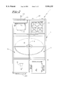
- FIG. 2 is a top elevational view of the enclosure illustrated in FIG. 1;
- FIG. 3 is a schematic diagram illustrating the path taken by that portion of the primary air flow into which energy is being introduced for transfer to the rotary heat wheel.
- the climate control apparatus or system generally designated 10 includes a main enclosure 11 through which a pair of discrete primary and secondary air flows are passed.
- the system 10 is designed to modify certain aspects of secondary air flowing to and from an environment, such as through the addition of heat or thermal energy to that flow.
- Enclosure 11 is divided into a pair of chambers including major chambers 12 and 13, with chamber 12 being designed to handle direct and otherwise create a primary flow of air, and with chamber 13 being designed to control and modify (heat) a secondary flow of air passing therethrough.
- a rotary energy exchange device in the form of a heat wheel generally designated 15 is provided for axial rotation between the primary and secondary major chambers, with wheel 15 incorporating discrete energy exchange means disposed radially outwardly from the axis, and with heat wheel 15 being powered for rotation by a motor, not shown.
- These discrete energy exchange means are provided for bilaterally receiving on the one hand and delivering on the other hand, energy which is delivered into the primary air flow.
- Rotary heat wheels have been utilized in the past, with such wheels being disclosed in U. S. Pat. 4,093,435 (Marron et al.).
- the '435 patent discloses a rotary regenerative heat energy exchanger which incorporates discrete webs of aluminum foil as an energy exchange means for transfer of sensible heat with minimal pressure drop across and through the thickness of the exchange portions of rotary heat wheel.
- a means is provided for creating primary and secondary air flows, with blower 18 being provided on the primary side 12, and with blower 19 being provided on the secondary side 13 and is powered by motor 19A. Blowers 18 and 19 create the means for moving and/or transferring the primary and secondary air flows through the system.
- Burner profile 21 is interposed within the primary chamber 12, and receives fresh air through inlet 20, along with a charge of partially spent recycled air from the primary air flow side.
- the flow of air from heat profile 21 is, in turn, passed across the arcuate segment housed within the primary chamber 12, and ultimately through blower 18 where a portion of the air is discharged to the atmosphere along the line and in the direction of the arrow 23.
- the recycled component may constitute between 75% and 95% of the overall primary air, with the desired amount depending, of course, upon the immediate conditions. Suffice it to say that the oxygen content of the primary air entering the burner profile must be at least about 10% to 20% oxygen.
- baffles as illustrated at 30 are provided for controlling diversion of the primary air flow, and with baffles 30 accordingly forcing a portion of the primary air back to the zone occupied by burner profile 21. It will be appreciated that other devices or components may be utilized to create the flow diversion, with such devices being, of course, known to those of conventional skill in the art.
- Burner profile 21 is designed to discharge gases to blending chamber 35, with chamber 35 receiving a charge of gases including combustion gases as indicated along line 36, and a flow of recycled primary air or gases as at 37.
- blending chamber 35 may be eliminated in a system design wherein phantom flow line 37A directs recycled gases directly to burner profile 21 to be blended with incoming fresh outdoor air prior to passing through burner profile 21.
- the primary air is passed through a 180° segment of rotary heat wheel 15. After passing through heat wheel 15, the primary air moves along the line indicated at 38 through blower 18, and with a portion being ultimately diverted into exhaust air as at 39, and with the balance becoming recycled air as at 37.
- outdoor air may enter the system at, for example, 0° F. and thereafter be blended with recycled air so that its temperature reaches a level of between about 50° F. and 70° F.
- This blended gas is then passed through the profile 21 and heated to 200° F.
- These heated gases are then passed across the primary side of the heat wheel where the flow is cooled to a temperature of, for example, 70° F.
- After passing through the heat wheel about 20% of the primary air is exhausted to atmosphere, with the remaining 80% being redirected back to the profile burner.
- Fresh outdoor air is added continuously in an amount equal to that being exhausted.
- the system of the present invention is readily adapted for use in a dehumidifying application.
- the heat wheel is provided with energy exchange means in the form of hygroscopic substances such as silica gel or the like. Moisture picked up from the secondary side is driven off upon exposure to the higher temperature gases on the primary side, and thus replenishing the ability of the silica gel to extract moisture from air passing through the heat wheel on the secondary side.
Abstract
Description
Claims (5)
Priority Applications (1)
| Application Number | Priority Date | Filing Date | Title |
|---|---|---|---|
| US09/128,211 US5941233A (en) | 1998-08-03 | 1998-08-03 | Indirect-fired heater with regeneration reclaim rotary heat exchanges |
Applications Claiming Priority (1)
| Application Number | Priority Date | Filing Date | Title |
|---|---|---|---|
| US09/128,211 US5941233A (en) | 1998-08-03 | 1998-08-03 | Indirect-fired heater with regeneration reclaim rotary heat exchanges |
Publications (1)
| Publication Number | Publication Date |
|---|---|
| US5941233A true US5941233A (en) | 1999-08-24 |
Family
ID=22434208
Family Applications (1)
| Application Number | Title | Priority Date | Filing Date |
|---|---|---|---|
| US09/128,211 Expired - Fee Related US5941233A (en) | 1998-08-03 | 1998-08-03 | Indirect-fired heater with regeneration reclaim rotary heat exchanges |
Country Status (1)
| Country | Link |
|---|---|
| US (1) | US5941233A (en) |
Cited By (6)
| Publication number | Priority date | Publication date | Assignee | Title |
|---|---|---|---|---|
| US20030026727A1 (en) * | 2001-05-16 | 2003-02-06 | Topp Daniel P. | Disinfestation apparatus utilizing heat |
| US6678994B2 (en) | 2001-05-22 | 2004-01-20 | Topp Construction Services, Inc. | Sanitary and phytosanitary pest control method by controlled application of heat |
| US20050051155A1 (en) * | 2003-08-12 | 2005-03-10 | Tomlinson John L. | Direct-fired, gas-fueled heater |
| US20060130508A1 (en) * | 2004-12-17 | 2006-06-22 | Foxconn Technology Co., Ltd | Total heat exchanger |
| US20070051243A1 (en) * | 2005-08-05 | 2007-03-08 | Boutall Charles A | High efficiency heating and drying using shielded radiant heater |
| US20070084105A1 (en) * | 2005-10-17 | 2007-04-19 | Rupp Industries, Inc. | Portable pest control system |
Citations (17)
| Publication number | Priority date | Publication date | Assignee | Title |
|---|---|---|---|---|
| US3695250A (en) * | 1970-12-03 | 1972-10-03 | Arco Flow Dynamics Inc | Rotary regenerative space heater |
| US4093435A (en) * | 1973-11-23 | 1978-06-06 | Wing Industries Inc. | Total heat energy exchangers |
| US4321961A (en) * | 1980-11-10 | 1982-03-30 | Midland-Ross Corporation | Thermal energy exchanging device |
| US4324545A (en) * | 1980-09-22 | 1982-04-13 | Gladd Industries, Inc. | Recirculating heater for processing oven |
| US4345897A (en) * | 1980-04-21 | 1982-08-24 | Stanton C Robert | Recirculating system for gas-fired furnace |
| US4384850A (en) * | 1981-06-17 | 1983-05-24 | Tri-Mark Metal Corporation | Recirculating air heater |
| US4426853A (en) * | 1981-01-26 | 1984-01-24 | Tokyo Shibaura Denki Kabushiki Kaisha | Air conditioning system |
| US4427374A (en) * | 1981-08-19 | 1984-01-24 | Phelps Dodge Industries, Inc. | Recirculation device |
| US4542782A (en) * | 1983-02-28 | 1985-09-24 | Erling Berner | Rotary-type heat exchanger |
| US4627485A (en) * | 1984-10-23 | 1986-12-09 | The Air Preheater Company, Inc. | Rotary regenerative heat exchanger for high temperature applications |
| US4967726A (en) * | 1988-05-24 | 1990-11-06 | Stelrad Group Limited | Space heating and ventilation systems for buildings |
| US5002484A (en) * | 1988-03-25 | 1991-03-26 | Shell Western E&P Inc. | Method and system for flue gas recirculation |
| US5562089A (en) * | 1994-06-07 | 1996-10-08 | Astle, Jr; William B. | Heating with a moving heat sink |
| US5590705A (en) * | 1994-07-12 | 1997-01-07 | Societe Anonyme Dite: Aerospatiale Societe Nationale Industrielle | Device for generating a hot air flow |
| US5603906A (en) * | 1991-11-01 | 1997-02-18 | Holman Boiler Works, Inc. | Low NOx burner |
| US5664620A (en) * | 1996-07-18 | 1997-09-09 | Abb Air Preheater Inc. | Rotary regenerative heat exchanger |
| US5732562A (en) * | 1996-08-13 | 1998-03-31 | Moratalla; Jose M. | Method and apparatus for regenerating desiccants in a closed cycle |
-
1998
- 1998-08-03 US US09/128,211 patent/US5941233A/en not_active Expired - Fee Related
Patent Citations (17)
| Publication number | Priority date | Publication date | Assignee | Title |
|---|---|---|---|---|
| US3695250A (en) * | 1970-12-03 | 1972-10-03 | Arco Flow Dynamics Inc | Rotary regenerative space heater |
| US4093435A (en) * | 1973-11-23 | 1978-06-06 | Wing Industries Inc. | Total heat energy exchangers |
| US4345897A (en) * | 1980-04-21 | 1982-08-24 | Stanton C Robert | Recirculating system for gas-fired furnace |
| US4324545A (en) * | 1980-09-22 | 1982-04-13 | Gladd Industries, Inc. | Recirculating heater for processing oven |
| US4321961A (en) * | 1980-11-10 | 1982-03-30 | Midland-Ross Corporation | Thermal energy exchanging device |
| US4426853A (en) * | 1981-01-26 | 1984-01-24 | Tokyo Shibaura Denki Kabushiki Kaisha | Air conditioning system |
| US4384850A (en) * | 1981-06-17 | 1983-05-24 | Tri-Mark Metal Corporation | Recirculating air heater |
| US4427374A (en) * | 1981-08-19 | 1984-01-24 | Phelps Dodge Industries, Inc. | Recirculation device |
| US4542782A (en) * | 1983-02-28 | 1985-09-24 | Erling Berner | Rotary-type heat exchanger |
| US4627485A (en) * | 1984-10-23 | 1986-12-09 | The Air Preheater Company, Inc. | Rotary regenerative heat exchanger for high temperature applications |
| US5002484A (en) * | 1988-03-25 | 1991-03-26 | Shell Western E&P Inc. | Method and system for flue gas recirculation |
| US4967726A (en) * | 1988-05-24 | 1990-11-06 | Stelrad Group Limited | Space heating and ventilation systems for buildings |
| US5603906A (en) * | 1991-11-01 | 1997-02-18 | Holman Boiler Works, Inc. | Low NOx burner |
| US5562089A (en) * | 1994-06-07 | 1996-10-08 | Astle, Jr; William B. | Heating with a moving heat sink |
| US5590705A (en) * | 1994-07-12 | 1997-01-07 | Societe Anonyme Dite: Aerospatiale Societe Nationale Industrielle | Device for generating a hot air flow |
| US5664620A (en) * | 1996-07-18 | 1997-09-09 | Abb Air Preheater Inc. | Rotary regenerative heat exchanger |
| US5732562A (en) * | 1996-08-13 | 1998-03-31 | Moratalla; Jose M. | Method and apparatus for regenerating desiccants in a closed cycle |
Cited By (10)
| Publication number | Priority date | Publication date | Assignee | Title |
|---|---|---|---|---|
| US20030026727A1 (en) * | 2001-05-16 | 2003-02-06 | Topp Daniel P. | Disinfestation apparatus utilizing heat |
| US6612067B2 (en) | 2001-05-16 | 2003-09-02 | Topp Construction Services, Inc. | Apparatus for and method of eradicating pests |
| US20040035044A1 (en) * | 2001-05-16 | 2004-02-26 | Topp Daniel P. | Apparatus for eradicating pests |
| US20060010791A1 (en) * | 2001-05-16 | 2006-01-19 | Topp Construction Services, Inc. | Method for converting a structure into a disinfestation apparatus |
| US6678994B2 (en) | 2001-05-22 | 2004-01-20 | Topp Construction Services, Inc. | Sanitary and phytosanitary pest control method by controlled application of heat |
| US20050051155A1 (en) * | 2003-08-12 | 2005-03-10 | Tomlinson John L. | Direct-fired, gas-fueled heater |
| US20060130508A1 (en) * | 2004-12-17 | 2006-06-22 | Foxconn Technology Co., Ltd | Total heat exchanger |
| US20070051243A1 (en) * | 2005-08-05 | 2007-03-08 | Boutall Charles A | High efficiency heating and drying using shielded radiant heater |
| US7563306B2 (en) * | 2005-08-05 | 2009-07-21 | Technologies Holdings Corporation | High efficiency heating and drying using shielded radiant heater |
| US20070084105A1 (en) * | 2005-10-17 | 2007-04-19 | Rupp Industries, Inc. | Portable pest control system |
Similar Documents
| Publication | Publication Date | Title |
|---|---|---|
| US4948392A (en) | Heat input for thermal regenerative desiccant systems | |
| US7338548B2 (en) | Dessicant dehumidifer for drying moist environments | |
| US5502975A (en) | Air conditioning system | |
| EP1188024B1 (en) | A method for heat and humidity exchange between two air streams and apparatus therefor | |
| US6406522B1 (en) | Dual mode air treatment apparatus and method | |
| US7373786B2 (en) | Desiccant dehumidification system | |
| US5526651A (en) | Open cycle desiccant cooling systems | |
| US5782104A (en) | Integrated air conditioning system with hot water production | |
| US6294000B1 (en) | Rotary concentrator and method of processing adsorbable pollutants | |
| CN204952595U (en) | Wet coating exhaust recycling treatment system | |
| US5941233A (en) | Indirect-fired heater with regeneration reclaim rotary heat exchanges | |
| CN103361458A (en) | A humidity adjusting device for a blast furnace blast system | |
| CN208536011U (en) | High-efficiency volatile organic waste gas treatment system | |
| CN101275771B (en) | Heat-reclaiming device of rotating wheel dehumidifier and thermal recovery method using the same | |
| JP3881067B2 (en) | Low dew point air supply system | |
| JP6793430B2 (en) | Dehumidifier | |
| Jin et al. | An adsorptive desiccant cooling using honeycomb rotor dehumidifier | |
| JP2002054838A (en) | Dehumidifying air conditioning apparatus | |
| US4901919A (en) | Air conditioning indirect heating and recuperative ventilation system | |
| KR950003071B1 (en) | Air condition system | |
| SU1442793A2 (en) | Apparatus for recovering energy in air conditioning systems | |
| JP3716089B2 (en) | Air conditioner | |
| JP2000283497A (en) | Adsorption dehumidification type air conditioner | |
| JP2022170779A (en) | Gas treatment device | |
| US20220241719A1 (en) | Dehumidification system |
Legal Events
| Date | Code | Title | Description |
|---|---|---|---|
| AS | Assignment |
Owner name: RUPP INDUSTRIES, INC., MINNESOTA Free format text: ASSIGNMENT OF ASSIGNORS INTEREST;ASSIGNORS:GRINOLS, DANIEL L.;CARNEY, CRAIG L.;PREKKER, RONALD J.;REEL/FRAME:009382/0665 Effective date: 19980731 |
|
| FPAY | Fee payment |
Year of fee payment: 4 |
|
| FEPP | Fee payment procedure |
Free format text: PAYOR NUMBER ASSIGNED (ORIGINAL EVENT CODE: ASPN); ENTITY STATUS OF PATENT OWNER: SMALL ENTITY |
|
| REMI | Maintenance fee reminder mailed | ||
| LAPS | Lapse for failure to pay maintenance fees | ||
| AS | Assignment |
Owner name: LASALLE BANK NATIONAL ASSOCIATION, MINNESOTA Free format text: SECURITY AGREEMENT;ASSIGNOR:RUPP INDUSTRIES, INC.;REEL/FRAME:019754/0865 Effective date: 20070828 |
|
| LAPS | Lapse for failure to pay maintenance fees |
Free format text: PATENT EXPIRED FOR FAILURE TO PAY MAINTENANCE FEES (ORIGINAL EVENT CODE: EXP.); ENTITY STATUS OF PATENT OWNER: SMALL ENTITY |
|
| STCH | Information on status: patent discontinuation |
Free format text: PATENT EXPIRED DUE TO NONPAYMENT OF MAINTENANCE FEES UNDER 37 CFR 1.362 |
|
| FP | Lapsed due to failure to pay maintenance fee |
Effective date: 20070824 |
|
| AS | Assignment |
Owner name: PRIVATEBANK AND TRUST COMPANY, THE, ILLINOIS Free format text: CORRECTIVE ASSIGNMENT TO CORRECT THE ERRORNEOUSLY RECORDED PATENT NUMBER 6941233 PREVIOUSLY RECORDED ON REEL 020995 FRAME 0089. ASSIGNOR(S) HEREBY CONFIRMS THE SECURITY AGREEMENT.;ASSIGNOR:TEMP-AIR, INC.;REEL/FRAME:021018/0703 Effective date: 20080506 |
|
| AS | Assignment |
Owner name: THE PRIVATEBANK AND TRUST COMPANY, ILLINOIS Free format text: CORRECTIVE ASSIGNMENT TO CORRECT THE INCORECT PATENT NUMBER 6941233 PREVIOUSLY RECORDED ON REEL 020995 FRAME 0089. ASSIGNOR HEREBY CONFIRMS THE SECURITY AGREEMENT;ASSIGNOR:TEMP-AIR, INC.;REEL/FRAME:021096/0187 Effective date: 20080506 |