US5914769A - Rear view mirror for divers - Google Patents
Rear view mirror for divers Download PDFInfo
- Publication number
- US5914769A US5914769A US09/209,806 US20980698A US5914769A US 5914769 A US5914769 A US 5914769A US 20980698 A US20980698 A US 20980698A US 5914769 A US5914769 A US 5914769A
- Authority
- US
- United States
- Prior art keywords
- clip
- mask
- locking
- main body
- mirror
- Prior art date
- Legal status (The legal status is an assumption and is not a legal conclusion. Google has not performed a legal analysis and makes no representation as to the accuracy of the status listed.)
- Expired - Fee Related
Links
- 239000011521 glass Substances 0.000 claims description 7
- 230000013011 mating Effects 0.000 claims 1
- 230000004438 eyesight Effects 0.000 abstract description 7
- 230000009189 diving Effects 0.000 abstract description 5
- 238000004519 manufacturing process Methods 0.000 abstract description 2
- 238000003860 storage Methods 0.000 description 6
- 238000002360 preparation method Methods 0.000 description 4
- 241000251730 Chondrichthyes Species 0.000 description 1
- 229920000122 acrylonitrile butadiene styrene Polymers 0.000 description 1
- 238000004140 cleaning Methods 0.000 description 1
- 239000003086 colorant Substances 0.000 description 1
- 230000000295 complement effect Effects 0.000 description 1
- 230000004313 glare Effects 0.000 description 1
- 238000003780 insertion Methods 0.000 description 1
- 230000037431 insertion Effects 0.000 description 1
- 238000009434 installation Methods 0.000 description 1
- 238000012423 maintenance Methods 0.000 description 1
- 238000000034 method Methods 0.000 description 1
- 238000012986 modification Methods 0.000 description 1
- 230000004048 modification Effects 0.000 description 1
- 230000000153 supplemental effect Effects 0.000 description 1
- XLYOFNOQVPJJNP-UHFFFAOYSA-N water Substances O XLYOFNOQVPJJNP-UHFFFAOYSA-N 0.000 description 1
Images


Classifications
-
- A—HUMAN NECESSITIES
- A63—SPORTS; GAMES; AMUSEMENTS
- A63B—APPARATUS FOR PHYSICAL TRAINING, GYMNASTICS, SWIMMING, CLIMBING, OR FENCING; BALL GAMES; TRAINING EQUIPMENT
- A63B33/00—Swimming equipment attachable to the head, e.g. swim caps or goggles
-
- B—PERFORMING OPERATIONS; TRANSPORTING
- B63—SHIPS OR OTHER WATERBORNE VESSELS; RELATED EQUIPMENT
- B63C—LAUNCHING, HAULING-OUT, OR DRY-DOCKING OF VESSELS; LIFE-SAVING IN WATER; EQUIPMENT FOR DWELLING OR WORKING UNDER WATER; MEANS FOR SALVAGING OR SEARCHING FOR UNDERWATER OBJECTS
- B63C11/00—Equipment for dwelling or working underwater; Means for searching for underwater objects
- B63C11/02—Divers' equipment
- B63C11/12—Diving masks
-
- G—PHYSICS
- G02—OPTICS
- G02C—SPECTACLES; SUNGLASSES OR GOGGLES INSOFAR AS THEY HAVE THE SAME FEATURES AS SPECTACLES; CONTACT LENSES
- G02C7/00—Optical parts
- G02C7/14—Mirrors; Prisms
-
- A—HUMAN NECESSITIES
- A63—SPORTS; GAMES; AMUSEMENTS
- A63B—APPARATUS FOR PHYSICAL TRAINING, GYMNASTICS, SWIMMING, CLIMBING, OR FENCING; BALL GAMES; TRAINING EQUIPMENT
- A63B2225/00—Miscellaneous features of sport apparatus, devices or equipment
- A63B2225/30—Maintenance
-
- B—PERFORMING OPERATIONS; TRANSPORTING
- B63—SHIPS OR OTHER WATERBORNE VESSELS; RELATED EQUIPMENT
- B63C—LAUNCHING, HAULING-OUT, OR DRY-DOCKING OF VESSELS; LIFE-SAVING IN WATER; EQUIPMENT FOR DWELLING OR WORKING UNDER WATER; MEANS FOR SALVAGING OR SEARCHING FOR UNDERWATER OBJECTS
- B63C11/00—Equipment for dwelling or working underwater; Means for searching for underwater objects
- B63C11/02—Divers' equipment
- B63C11/12—Diving masks
- B63C2011/126—Diving masks comprising periscopes, mirrors, or the like; Periscopes, mirrors, or the like specially adapted for use with diving masks
Definitions
- the invention relates to diver's equipment, and more specifically, the invention relates to a rear view mirror which is attachable to most diving masks in production.
- a common problem that divers currently have is the inability to see what is behind them while underwater. First, it is important to know where other divers are located since it is possible to swim away without knowing where the other divers are and the diver may be out of sight of following divers. Second, a diver always has the fear of a shark or other dangerous sea creature coming up from behind in their blind spot.
- U.S. Pat. No. 5,764,334 to Berke discloses a diving mask with supplemental vertical, lateral and posterior fields of vision.
- a pair of sealed compartments at opposite ends of the diving mask have rotatable mirrorized surfaces which reflect light rays from objects above, below, on the side, and rear of the mask into a diver's view.
- U.S. Pat. No. 5,170,190 to Berke discloses a water sportsman's face mask for viewing objects above and below the line of vision.
- a lens is mounted in front of the frame and a pair of triangular prisms mounted on the lens.
- the instant invention is designed to overcome the rear view problems of the prior art with a mask mounted, adjustable rear view mirror.
- the invention consists of a mirror retaining device which is clipped by an attachment means to the top of the mask allowing a convex mirror to be positioned in its operational position within the line of vision of the diver thus facilitating an extension of the diver's view behind, above and to each side as needed.
- a mirror retaining device provides flexibility of adjustment upwards or downwards. The mirror is slightly convex to prevent direct glare of the sun from being reflected into the eyes of the user and to provide a wider angle of view.
- FIG. 1. is a perspective view of a diver's mask having an adjustable mirror retaining and storage device in accordance with the invention.
- FIG. 2. is a perspective view of a diver's mask having an adjustable mirror retaining and storage device showing the mirror rotated 180 degrees as an alternative application.
- FIG. 3. is an exploded view showing components of the mirror retaining device.
- FIG. 4. is a perspective view showing the mirror-retaining device with an alternative embodiment of the mirror mounting apparatus.
- FIG. 5. is an exploded view showing components of the mirror retaining device and an alternative embodiment of the attachment apparatus.
- FIG. 6. is a perspective view of an alternative embodiment of the attachment apparatus showing a cross sectional detail of the attachment means used to adjust the fitting of the mirror retaining device for different mask configuration.
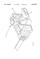
- FIG. 7. is a perspective view of an alternate embodiment of the attachment apparatus showing the attachment means in place as it would be used to adjust the fitting of the mirror retaining device for different mask configurations.
- FIGS. 8-10 are various elevations of an alternative embodiment of the attachment apparatus in accordance with the invention.
- FIGS. 11-13 are various elevations of a further alternative embodiment of the attachment apparatus.
- FIGS. 14-16 are various elevations of a further alternative embodiment of the attachment apparatus.
- FIGS. 17-19 are various elevations of the rear clip attachment apparatus.
- FIGS. 20-21 are front and side views respectively, of the locking clip device used to retain in place other components of the attachment means used to mount the mirror retaining device on the swim mask.
- FIGS. 22-25 are various elevations of a first embodiment of the attachment means for the convex mirror device.
- FIGS. 26-29 are various elevations of a second and preferred embodiment of the attachment means for the convex mirror device.
- FIG. 30 is a plan elevation of the main body of the mirror attachment and retaining device showing a sectional plan view and an end elevation of its end cap.
- FIG. 31 is a side elevation of the main body of the mirror attachment and retaining device showing also a cross-sectional side view of its end cap.
- FIG. 32 is a plan elevation of the main body of the mirror attachment and retaining device positioned adjacent to and separate from its end cap, with the mirror support arm being inserted into the end cap in preparation for its attachment to the device in accordance with the invention.
- FIG. 33 is a plan elevation of the main body of the mirror attachment and retaining device positioned adjacent to and separate from its end cap, with the mirror support arm being further inserted into the end cap in preparation for its attachment to the device.
- FIG. 34 is a plan elevation of the main body of the mirror attachment and retaining device positioned adjacent to and separate from its end cap with the mirror support arm being rotated into its operational position in the end cap in preparation for its attachment to the device.
- FIG. 35 is a plan elevation of the main body of the mirror attachment and retaining device with its end cap now attached, with the mirror support arm being rotated from its operational position in the end cap in preparation for its storage within the device.
- FIG. 36 is a plan elevation of the main body of the mirror attachment and retaining device with its end cap now attached, with the mirror support arm being slid into its storage position within the device.
- FIGS. 37-41 show the assembly and mounting sequence for the mirror retaining device as it is first assembled and then affixed into its operating position on the swim mask.
- FIGS. 1 and 2 a diver's mask is fitted with a mirror retaining device 10 which is clipped by an attachment means to the top of the mask 50 allowing convex mirror 44 to be positioned in its operational position within the line of vision of the diver thus facilitating an extension of the diver's view behind, above and to each side as needed.
- mirror retaining device 10 is shown in an exploded view wherein the relationship between each of its components is shown so that the main body 11 is positioned away from end cap 12 and top locking clip 19 into its pre-assembly position above.
- Rear locking clip 24 and front locking clip 27 are positioned below main body 11.
- mirror arm 41 Prior to mounting mirror-retaining device 10 to the top of the mask 50, mirror arm 41 is slid through end cap 12 as shown in FIGS. 32-36.
- end cap 12 is tilted to allow mirror arm 41 (without convex mirror 44 attached) to be passed through.
- FIG. 33 end cap 12 is slid toward main body 11 and mirror arm 41 is allowed to pass fully into end cap 12.
- FIG. 34 with mirror arm 41 now fully in place in end cap 12, it can be swiveled in the direction of arrow 35 to its operational position.
- end cap 12 is shown clipped onto main body 11 and mirror arm 41 is raised in the direction of arrow 36.
- FIG. 36 shows mirror 44 in its storage position
- arrow 37 shows the direction mirror arm 41 is slid to place it in its storage position inside main body 11.
- FIG. 37 wherein the assembly/mounting sequence of the various components of the mirror mounting device 10 is commenced.
- a side elevation of mask 50 is shown partially in section to reveal the relationship between mask skirt 51, mask glass 52, front locking clip 27 and rear locking clip 24.
- Optional leveling pin 21 can be used where a swim mask 50 is made without a level shoulder for the mirror mounting device 10 to rest securely thereupon).
- FIGS. 30 and 31 show the position of the mounting holes 20 for leveling pins 21 and 21'. Mounting commences with the placement of rear locking clip 24 beneath mask skirt 51. Front locking clip 27 is positioned with its lip firmly against mask glass 52.
- FIG. 2 shows the relative positions of main body 11, top locking clip 19, rear locking clip 24, front locking clip 27, and top clip chamber 18.
- Main body 11 is lowered into position.
- FIG. 38 main body 11 has been lowered over the upright faces of rear locking clip 24 and front locking clip 27 so that they are confined within top clip chamber 18.
- top clip 19 has a locking ridge 23 (shown enlarged in FIGS. 20-21).
- front and rear locking clips 24 and 27 respectively are offered up into top clip chamber 18, top locking clip 19 is pushed down into top clip chamber 18 causing locking ridge 23 to engage the serrated face 25 (See FIGS. 11-13 for enlargement of front locking clip 27 and FIGS. 17-19 for enlargement of rear locking clip 24).
- FIGS. 40 and 41 show the final operational installation of the mirror-mounting device 10.
- FIG. 41 shows the range of movement of the mirror arm assembly. Securing the device 10 through the use of adjustable clips as described herein, facilitates the use of swim masks of different types and specifications.
- FIGS. 22-29 a rear view of convex mirror 44 is shown in FIG. 22 and FIGS. 23-25 show other views which illustrate the mounting attachment 39.
- This fitting is used with a mirror arm 41 without a second ball joint whereas in FIGS. 26-29 a ball joint socket 43 is shown as the preferred embodiment.
- FIGS. 3 and 4 show the differences between the straight mirror arm 41 with one ball-joint end 40 (FIG. 3) and a "U" shaped mirror arm 41 with an additional ball-joint 42 at its furthermost end.
- FIG. 4 also shows convex mirror 44 in two of the many possible positions to which it can be adjusted using the ball-socket joints 40 at either end of mirror arm 41.
- the mirror arm 41 can be adjusted at a 20° angle up and down and from 180° to 90°, and the mirror 44 can swivel 360°.
- adjustable locking clips 29, locking clip slots 31 are shown in sectional detail to illustrate locking ridge 32 (present on each side of aperture 31).
- adjustable locking clips 29 are used to facilitate a variable adjustment of the distances between the vertical plane of front locking clip 26 and mask glass 52 (FIGS. 37-39), thus permitting the use of swim masks with differing specifications.
- Front clip 27 is used where a particular mask configuration permits its use without need to adjust in relation to the mask glass 52.
- front locking clip 28 through the addition of ridges 34, permits its use on masks where there is no need to adjust it in relation to the mask glass 52.
- the preferred embodiment is as shown in FIG. 6 with adjustable front clip 26.
- the mirror mounting device 10 of the invention may be made from high-quality, ABS plastic and in a variety of colors.
- Mirror 40 is a marine mirror.
- the present invention provides a novel diver's rear view mirror which can be mounted on most existing dive masks. It is contemplated that other embodiments and/or modifications may be made in the present invention without departure from inventive concepts manifested by the disclosed embodiments. It is expressly intended, therefore, that the foregoing description is illustrative only of preferred embodiments, not limiting, and that the true spirit and scope of the invention be determined by reference to the appended claims.
Landscapes
- Health & Medical Sciences (AREA)
- General Health & Medical Sciences (AREA)
- Ophthalmology & Optometry (AREA)
- Physics & Mathematics (AREA)
- Pulmonology (AREA)
- Physical Education & Sports Medicine (AREA)
- General Physics & Mathematics (AREA)
- Optics & Photonics (AREA)
- Engineering & Computer Science (AREA)
- Mechanical Engineering (AREA)
- Ocean & Marine Engineering (AREA)
- Mirrors, Picture Frames, Photograph Stands, And Related Fastening Devices (AREA)
Abstract
The invention is directed to a rear view mirror which is attachable to most diving masks in production. A mirror retaining device is clipped by an attachment to the mask and a convex mirror is positioned in an operational position within the line of vision of the diver.
Description
This is a Continuation of Provisional Application Ser. No. 60/082,742, Filed Apr. 23, 1998.
1. Field of the Invention
The invention relates to diver's equipment, and more specifically, the invention relates to a rear view mirror which is attachable to most diving masks in production.
2. Background of the Invention
A common problem that divers currently have is the inability to see what is behind them while underwater. First, it is important to know where other divers are located since it is possible to swim away without knowing where the other divers are and the diver may be out of sight of following divers. Second, a diver always has the fear of a shark or other dangerous sea creature coming up from behind in their blind spot.
One prior art device is shown in U.S. Pat. No. 5,216,454 to Berke which discloses a sportsman's face mask for viewing objects in the opposite direction of the normal line of vision. At least one prism, having a pair of complementary faces which are inclined to the and internally reflect rays from objects behind the swimmer into his forward field of vision, is mounted in front of the lens.
U.S. Pat. No. 5,764,334 to Berke discloses a diving mask with supplemental vertical, lateral and posterior fields of vision. A pair of sealed compartments at opposite ends of the diving mask have rotatable mirrorized surfaces which reflect light rays from objects above, below, on the side, and rear of the mask into a diver's view.
U.S. Pat. No. 5,170,190 to Berke discloses a water sportsman's face mask for viewing objects above and below the line of vision. A lens is mounted in front of the frame and a pair of triangular prisms mounted on the lens.
The instant invention is designed to overcome the rear view problems of the prior art with a mask mounted, adjustable rear view mirror.
The invention consists of a mirror retaining device which is clipped by an attachment means to the top of the mask allowing a convex mirror to be positioned in its operational position within the line of vision of the diver thus facilitating an extension of the diver's view behind, above and to each side as needed. A mirror retaining device provides flexibility of adjustment upwards or downwards. The mirror is slightly convex to prevent direct glare of the sun from being reflected into the eyes of the user and to provide a wider angle of view.
FIG. 1. is a perspective view of a diver's mask having an adjustable mirror retaining and storage device in accordance with the invention.
FIG. 2. is a perspective view of a diver's mask having an adjustable mirror retaining and storage device showing the mirror rotated 180 degrees as an alternative application.
FIG. 3. is an exploded view showing components of the mirror retaining device.
FIG. 4. is a perspective view showing the mirror-retaining device with an alternative embodiment of the mirror mounting apparatus.
FIG. 5. is an exploded view showing components of the mirror retaining device and an alternative embodiment of the attachment apparatus.
FIG. 6. is a perspective view of an alternative embodiment of the attachment apparatus showing a cross sectional detail of the attachment means used to adjust the fitting of the mirror retaining device for different mask configuration.
FIG. 7. is a perspective view of an alternate embodiment of the attachment apparatus showing the attachment means in place as it would be used to adjust the fitting of the mirror retaining device for different mask configurations.
FIGS. 8-10 are various elevations of an alternative embodiment of the attachment apparatus in accordance with the invention.
FIGS. 11-13 are various elevations of a further alternative embodiment of the attachment apparatus.
FIGS. 14-16 are various elevations of a further alternative embodiment of the attachment apparatus.
FIGS. 17-19 are various elevations of the rear clip attachment apparatus.
FIGS. 20-21 are front and side views respectively, of the locking clip device used to retain in place other components of the attachment means used to mount the mirror retaining device on the swim mask.
FIGS. 22-25 are various elevations of a first embodiment of the attachment means for the convex mirror device.
FIGS. 26-29 are various elevations of a second and preferred embodiment of the attachment means for the convex mirror device.
FIG. 30 is a plan elevation of the main body of the mirror attachment and retaining device showing a sectional plan view and an end elevation of its end cap.
FIG. 31 is a side elevation of the main body of the mirror attachment and retaining device showing also a cross-sectional side view of its end cap.
FIG. 32 is a plan elevation of the main body of the mirror attachment and retaining device positioned adjacent to and separate from its end cap, with the mirror support arm being inserted into the end cap in preparation for its attachment to the device in accordance with the invention.
FIG. 33 is a plan elevation of the main body of the mirror attachment and retaining device positioned adjacent to and separate from its end cap, with the mirror support arm being further inserted into the end cap in preparation for its attachment to the device.
FIG. 34 is a plan elevation of the main body of the mirror attachment and retaining device positioned adjacent to and separate from its end cap with the mirror support arm being rotated into its operational position in the end cap in preparation for its attachment to the device.
FIG. 35 is a plan elevation of the main body of the mirror attachment and retaining device with its end cap now attached, with the mirror support arm being rotated from its operational position in the end cap in preparation for its storage within the device.
FIG. 36 is a plan elevation of the main body of the mirror attachment and retaining device with its end cap now attached, with the mirror support arm being slid into its storage position within the device.
FIGS. 37-41 show the assembly and mounting sequence for the mirror retaining device as it is first assembled and then affixed into its operating position on the swim mask.
Referring now to the drawings wherein like numerals designate like and corresponding parts throughout the several views, in FIGS. 1 and 2 a diver's mask is fitted with a mirror retaining device 10 which is clipped by an attachment means to the top of the mask 50 allowing convex mirror 44 to be positioned in its operational position within the line of vision of the diver thus facilitating an extension of the diver's view behind, above and to each side as needed. In FIG. 3, mirror retaining device 10 is shown in an exploded view wherein the relationship between each of its components is shown so that the main body 11 is positioned away from end cap 12 and top locking clip 19 into its pre-assembly position above. Rear locking clip 24 and front locking clip 27 are positioned below main body 11.
Prior to mounting mirror-retaining device 10 to the top of the mask 50, mirror arm 41 is slid through end cap 12 as shown in FIGS. 32-36. Referring now to FIG. 32, end cap 12 is tilted to allow mirror arm 41 (without convex mirror 44 attached) to be passed through. In FIG. 33, end cap 12 is slid toward main body 11 and mirror arm 41 is allowed to pass fully into end cap 12. In FIG. 34, with mirror arm 41 now fully in place in end cap 12, it can be swiveled in the direction of arrow 35 to its operational position. In FIG. 35, end cap 12 is shown clipped onto main body 11 and mirror arm 41 is raised in the direction of arrow 36. FIG. 36 shows mirror 44 in its storage position, arrow 37 shows the direction mirror arm 41 is slid to place it in its storage position inside main body 11.
Referring now to FIG. 37, wherein the assembly/mounting sequence of the various components of the mirror mounting device 10 is commenced. A side elevation of mask 50 is shown partially in section to reveal the relationship between mask skirt 51, mask glass 52, front locking clip 27 and rear locking clip 24. (Optional leveling pin 21 can be used where a swim mask 50 is made without a level shoulder for the mirror mounting device 10 to rest securely thereupon).
FIGS. 30 and 31 show the position of the mounting holes 20 for leveling pins 21 and 21'. Mounting commences with the placement of rear locking clip 24 beneath mask skirt 51. Front locking clip 27 is positioned with its lip firmly against mask glass 52.
FIG. 2 shows the relative positions of main body 11, top locking clip 19, rear locking clip 24, front locking clip 27, and top clip chamber 18. Main body 11 is lowered into position. In FIG. 38, main body 11 has been lowered over the upright faces of rear locking clip 24 and front locking clip 27 so that they are confined within top clip chamber 18. Referring now to FIG. 3, top clip 19 has a locking ridge 23 (shown enlarged in FIGS. 20-21). As front and rear locking clips 24 and 27 respectively are offered up into top clip chamber 18, top locking clip 19 is pushed down into top clip chamber 18 causing locking ridge 23 to engage the serrated face 25 (See FIGS. 11-13 for enlargement of front locking clip 27 and FIGS. 17-19 for enlargement of rear locking clip 24). The simultaneous insertion of locking clips 24 and 27 from the bottom and top locking clip 19 from the top, results in a series of clicks as the serrations 25 on the clip 19 faces and locking ridge 23 on top clip 19 engage. Said engagement is what locks the device firmly in position atop the swim mask 50 as shown in FIG. 39. Mirror arm 41 and convex mirror 44 are omitted from FIGS. 37-39 for clarity. FIGS. 40 and 41 show the final operational installation of the mirror-mounting device 10. FIG. 41 shows the range of movement of the mirror arm assembly. Securing the device 10 through the use of adjustable clips as described herein, facilitates the use of swim masks of different types and specifications.
Referring now to FIGS. 22-29, a rear view of convex mirror 44 is shown in FIG. 22 and FIGS. 23-25 show other views which illustrate the mounting attachment 39. This fitting is used with a mirror arm 41 without a second ball joint whereas in FIGS. 26-29 a ball joint socket 43 is shown as the preferred embodiment. FIGS. 3 and 4 show the differences between the straight mirror arm 41 with one ball-joint end 40 (FIG. 3) and a "U" shaped mirror arm 41 with an additional ball-joint 42 at its furthermost end. FIG. 4 also shows convex mirror 44 in two of the many possible positions to which it can be adjusted using the ball-socket joints 40 at either end of mirror arm 41. The mirror arm 41 can be adjusted at a 20° angle up and down and from 180° to 90°, and the mirror 44 can swivel 360°.
Referring now to FIGS. 5-8, specifically to the characteristics of front locking clip 26, in the enlargement of front locking clip 26 and its ancillary components, adjustable locking clips 29, locking clip slots 31 are shown in sectional detail to illustrate locking ridge 32 (present on each side of aperture 31). In use, adjustable locking clips 29 are used to facilitate a variable adjustment of the distances between the vertical plane of front locking clip 26 and mask glass 52 (FIGS. 37-39), thus permitting the use of swim masks with differing specifications. The characteristic use of serrated faces and locking ridges throughout the instant device provides a positive method of fixing together the component parts into a compact resilient unit, which is secure enough to remain in position atop a diver's mask while diving, while retaining the ease of disassembly required for routine maintenance cleaning, etc.
Referring now to FIGS. 11-16, these are alternate embodiments of front locking clips. Front clip 27 is used where a particular mask configuration permits its use without need to adjust in relation to the mask glass 52. Similarly, front locking clip 28, through the addition of ridges 34, permits its use on masks where there is no need to adjust it in relation to the mask glass 52. The preferred embodiment is as shown in FIG. 6 with adjustable front clip 26.
The mirror mounting device 10 of the invention may be made from high-quality, ABS plastic and in a variety of colors. Mirror 40 is a marine mirror.
Thus it will be appreciated that the present invention provides a novel diver's rear view mirror which can be mounted on most existing dive masks. It is contemplated that other embodiments and/or modifications may be made in the present invention without departure from inventive concepts manifested by the disclosed embodiments. It is expressly intended, therefore, that the foregoing description is illustrative only of preferred embodiments, not limiting, and that the true spirit and scope of the invention be determined by reference to the appended claims.
Claims (9)
1. A rear view mirror device for mounting on a diver's mask, said device consisting of:
a main body having a ball socket and a pair of retainer clips formed at a first end, a mating guide formed at a second end and a chamber formed through said body and perpendicular to said body,
an end cap having a pair of clip apertures and a ball socket formed therein,
a mirror arm having a first end and a second end, said mirror arm having a ball joint formed at said first end and a right angle bend formed therein, said mirror arm second end being inserted through said ball socket formed within said end cap, said ball joint being inserted within said main body ball socket and said end cap clip apertures being mated with said main body retainer clips thereby forming a single unit,
a front locking clip and a rear locking clip, said front locking clip positioned on said mask and said front locking clip positioned firmly against said mask, said main body chamber being combined with said front and rear locking clips,
a top locking clip being positioned within said main body chamber and combined with said front and rear locking clips thereby locking said main body firmly on said diver's mask, and
a convex mirror pivotally mounted on said mirror arm second end.
2. A rear view mirror device for mounting on a diver's mask recited in claim 1 wherein said top clip contains a locking ridge and said front locking clip contains a serrated face for locking said top clip in position when assembled together.
3. A rear view mirror device for mounting on a diver's mask recited in claim 1 wherein said said front locking clip is formed with adjustable locking clips forming a variable adjustment of distances to accommodate different size masks.
4. A rear view mirror device for mounting on a diver's mask recited in claim 1 wherein said mirror arm second end is formed with a ball joint and said mirror is formed with a ball socket for assembling said mirror to said mirror arm.
5. A rear view mirror device for mounting on a diver's mask recited in claim 1 wherein said main body is formed with a pair of leveling pin holes and a pair of leveling pins are inserted in said leveling pin holes.
6. A locking device for mounting a main body on the top of a mask having a mask skirt and a mask glass, said device consisting of:
a main body having a first clip chamber and a second clip chamber formed therein, said clip chambers being spaced apart, and parallel to each other, said main body being positioned on the top of the mask, above said mask skirt,
a rear locking clip having a first end and a second end, said first end being inserted under said mask skirt and said second end being inserted within said first clip chamber,
a front locking clip having a first end and a second end, said first end being inserted within said second chamber and said second end being positioned against said mask glass, and
a top locking clip being inserted within said main body first and second clip chambers, thereby engaging said front locking clip and said rear locking clip into a secure position atop said mask skirt.
7. A locking device for mounting a main body on the top of a mask recited in claim 6 wherein said top clip contains a locking ridge and said front locking clip contains a serrated face for locking said top clip in position when assembled together.
8. A locking device for mounting a main body on the top of a mask recited in claim 6 wherein said front locking clip is formed with adjustable locking clips forming a variable adjustment of distances to accommodate different size masks.
9. A locking device for mounting a main body on the top of a mask recited in claim 6 wherein said main body is formed with a pair of leveling pin holes and a pair of leveling pins are inserted in said leveling pin holes.
Priority Applications (1)
| Application Number | Priority Date | Filing Date | Title |
|---|---|---|---|
| US09/209,806 US5914769A (en) | 1998-04-23 | 1998-12-11 | Rear view mirror for divers |
Applications Claiming Priority (2)
| Application Number | Priority Date | Filing Date | Title |
|---|---|---|---|
| US8274298P | 1998-04-23 | 1998-04-23 | |
| US09/209,806 US5914769A (en) | 1998-04-23 | 1998-12-11 | Rear view mirror for divers |
Publications (1)
| Publication Number | Publication Date |
|---|---|
| US5914769A true US5914769A (en) | 1999-06-22 |
Family
ID=26767793
Family Applications (1)
| Application Number | Title | Priority Date | Filing Date |
|---|---|---|---|
| US09/209,806 Expired - Fee Related US5914769A (en) | 1998-04-23 | 1998-12-11 | Rear view mirror for divers |
Country Status (1)
| Country | Link |
|---|---|
| US (1) | US5914769A (en) |
Cited By (7)
| Publication number | Priority date | Publication date | Assignee | Title |
|---|---|---|---|---|
| US20030195025A1 (en) * | 1995-10-17 | 2003-10-16 | Hill Otho Dale | System including card game dispensing shoe and method |
| US20040019959A1 (en) * | 2002-08-02 | 2004-02-05 | Bloom Walter L. | Dive mask with integral side mounted rear view mirrors |
| FR2859641A1 (en) * | 2003-09-15 | 2005-03-18 | Maurice Aiach | Learning and physical rehabilitation device for swimmer, has removable cup provided at top of tube for placing ball that is maintained by thin cord whose ends are connected to each other |
| US20070126978A1 (en) * | 2007-03-12 | 2007-06-07 | David Morales | Diving Viewing Device |
| USD594780S1 (en) | 2008-05-05 | 2009-06-23 | Standard Car Truck Company | Auto-rack railroad car vehicle positioning device |
| WO2015090166A1 (en) * | 2013-12-16 | 2015-06-25 | 尹君 | Novel sport goggles and display device thereof |
| FR3106984A1 (en) * | 2020-02-06 | 2021-08-13 | Valerie COIFFIER | Front swim mirror |
Citations (2)
| Publication number | Priority date | Publication date | Assignee | Title |
|---|---|---|---|---|
| US1431147A (en) * | 1917-10-08 | 1922-10-10 | Helge A Borresen | Reflector |
| US5764335A (en) * | 1996-08-09 | 1998-06-09 | Berke; Joseph J. | Eyewear for extending the normal field of vision |
-
1998
- 1998-12-11 US US09/209,806 patent/US5914769A/en not_active Expired - Fee Related
Patent Citations (2)
| Publication number | Priority date | Publication date | Assignee | Title |
|---|---|---|---|---|
| US1431147A (en) * | 1917-10-08 | 1922-10-10 | Helge A Borresen | Reflector |
| US5764335A (en) * | 1996-08-09 | 1998-06-09 | Berke; Joseph J. | Eyewear for extending the normal field of vision |
Cited By (7)
| Publication number | Priority date | Publication date | Assignee | Title |
|---|---|---|---|---|
| US20030195025A1 (en) * | 1995-10-17 | 2003-10-16 | Hill Otho Dale | System including card game dispensing shoe and method |
| US20040019959A1 (en) * | 2002-08-02 | 2004-02-05 | Bloom Walter L. | Dive mask with integral side mounted rear view mirrors |
| FR2859641A1 (en) * | 2003-09-15 | 2005-03-18 | Maurice Aiach | Learning and physical rehabilitation device for swimmer, has removable cup provided at top of tube for placing ball that is maintained by thin cord whose ends are connected to each other |
| US20070126978A1 (en) * | 2007-03-12 | 2007-06-07 | David Morales | Diving Viewing Device |
| USD594780S1 (en) | 2008-05-05 | 2009-06-23 | Standard Car Truck Company | Auto-rack railroad car vehicle positioning device |
| WO2015090166A1 (en) * | 2013-12-16 | 2015-06-25 | 尹君 | Novel sport goggles and display device thereof |
| FR3106984A1 (en) * | 2020-02-06 | 2021-08-13 | Valerie COIFFIER | Front swim mirror |
Similar Documents
| Publication | Publication Date | Title |
|---|---|---|
| US12348843B2 (en) | Image orientation control for a portable digital video camera | |
| US5914769A (en) | Rear view mirror for divers | |
| US9335536B2 (en) | Visual target acquisition scope system | |
| US20080186584A1 (en) | Spring-biased multi-axis articulating lens cover | |
| US8109681B2 (en) | Support | |
| US6318912B1 (en) | Adapter having a tilt and shift mechanism | |
| US5564132A (en) | Diving mask with an arcuate lens | |
| US7571563B2 (en) | Flexible supports for rifles, spotting scopes, and the like | |
| US20110296732A1 (en) | Articulating mount for weapon sight accessory | |
| CA2212655C (en) | Swimming or diving goggles | |
| US20110239354A1 (en) | Helmet mounting system and mounting shoe interface | |
| US9896168B1 (en) | Swing range adjustable fin assembly | |
| US10137969B2 (en) | Face mask with mount for imaging device | |
| US10661866B1 (en) | Scuba regulator system mount system | |
| US5604631A (en) | Sliding binocular body | |
| US5216454A (en) | Water sportsman's face mask for viewing objects in the opposite direction of the normal line of vision | |
| US5980035A (en) | Mirrorized compartments for a driver's mask | |
| US20130094849A1 (en) | Viewer accessory for camera | |
| EP0014525A1 (en) | Forward viewing aid for vehicle drivers | |
| EP0720498A1 (en) | Orientation aid for use when swimming on the back | |
| Li et al. | Assessment on the situation of water quality in Liaodong Bay shallow waters. | |
| US5694243A (en) | Sliding binocular body | |
| US5452034A (en) | Regulated parallax compensation system for a camera finder | |
| US6439716B1 (en) | Spectacles | |
| CN214861036U (en) | Diving goggles with camera shooting function |
Legal Events
| Date | Code | Title | Description |
|---|---|---|---|
| REMI | Maintenance fee reminder mailed | ||
| LAPS | Lapse for failure to pay maintenance fees | ||
| STCH | Information on status: patent discontinuation |
Free format text: PATENT EXPIRED DUE TO NONPAYMENT OF MAINTENANCE FEES UNDER 37 CFR 1.362 |
|
| FP | Lapsed due to failure to pay maintenance fee |
Effective date: 20030622 |