US5911539A - Interconnected block system - Google Patents
Interconnected block system Download PDFInfo
- Publication number
- US5911539A US5911539A US08/763,948 US76394896A US5911539A US 5911539 A US5911539 A US 5911539A US 76394896 A US76394896 A US 76394896A US 5911539 A US5911539 A US 5911539A
- Authority
- US
- United States
- Prior art keywords
- block
- matrix
- sheet
- interconnected
- matrix material
- Prior art date
- Legal status (The legal status is an assumption and is not a legal conclusion. Google has not performed a legal analysis and makes no representation as to the accuracy of the status listed.)
- Expired - Lifetime
Links
Images


Classifications
-
- E—FIXED CONSTRUCTIONS
- E02—HYDRAULIC ENGINEERING; FOUNDATIONS; SOIL SHIFTING
- E02B—HYDRAULIC ENGINEERING
- E02B3/00—Engineering works in connection with control or use of streams, rivers, coasts, or other marine sites; Sealings or joints for engineering works in general
- E02B3/04—Structures or apparatus for, or methods of, protecting banks, coasts, or harbours
- E02B3/12—Revetment of banks, dams, watercourses, or the like, e.g. the sea-floor
- E02B3/122—Flexible prefabricated covering elements, e.g. mats, strips
-
- E—FIXED CONSTRUCTIONS
- E02—HYDRAULIC ENGINEERING; FOUNDATIONS; SOIL SHIFTING
- E02B—HYDRAULIC ENGINEERING
- E02B3/00—Engineering works in connection with control or use of streams, rivers, coasts, or other marine sites; Sealings or joints for engineering works in general
- E02B3/04—Structures or apparatus for, or methods of, protecting banks, coasts, or harbours
- E02B3/12—Revetment of banks, dams, watercourses, or the like, e.g. the sea-floor
- E02B3/14—Preformed blocks or slabs for forming essentially continuous surfaces; Arrangements thereof
-
- E—FIXED CONSTRUCTIONS
- E02—HYDRAULIC ENGINEERING; FOUNDATIONS; SOIL SHIFTING
- E02D—FOUNDATIONS; EXCAVATIONS; EMBANKMENTS; UNDERGROUND OR UNDERWATER STRUCTURES
- E02D29/00—Independent underground or underwater structures; Retaining walls
- E02D29/02—Retaining or protecting walls
-
- E—FIXED CONSTRUCTIONS
- E02—HYDRAULIC ENGINEERING; FOUNDATIONS; SOIL SHIFTING
- E02D—FOUNDATIONS; EXCAVATIONS; EMBANKMENTS; UNDERGROUND OR UNDERWATER STRUCTURES
- E02D29/00—Independent underground or underwater structures; Retaining walls
- E02D29/02—Retaining or protecting walls
- E02D29/0225—Retaining or protecting walls comprising retention means in the backfill
-
- E—FIXED CONSTRUCTIONS
- E02—HYDRAULIC ENGINEERING; FOUNDATIONS; SOIL SHIFTING
- E02D—FOUNDATIONS; EXCAVATIONS; EMBANKMENTS; UNDERGROUND OR UNDERWATER STRUCTURES
- E02D17/00—Excavations; Bordering of excavations; Making embankments
- E02D17/20—Securing of slopes or inclines
- E02D17/202—Securing of slopes or inclines with flexible securing means
-
- E—FIXED CONSTRUCTIONS
- E02—HYDRAULIC ENGINEERING; FOUNDATIONS; SOIL SHIFTING
- E02D—FOUNDATIONS; EXCAVATIONS; EMBANKMENTS; UNDERGROUND OR UNDERWATER STRUCTURES
- E02D17/00—Excavations; Bordering of excavations; Making embankments
- E02D17/20—Securing of slopes or inclines
- E02D17/205—Securing of slopes or inclines with modular blocks, e.g. pre-fabricated
Definitions
- This invention relates to an interconnected block system including concrete or concrete-like blocks cast and mechanically interconnected on top of an underlying matrix formed by a grid-like geosynthetic material or geocomposite which may include a sorbent material to remove contaminants from environmental water.
- the invention also includes means for splicing individual sections of the matrix material as well as means and techniques for lifting, placing and securing large sections of the matrix for use, inter alia, as revetments, pavements, channel linings, and other special lining systems in erosion control, waste containment and paving applications.
- a second layer of grid-like geosynthetic material may be mechanically secured on top of the interconnected block system.
- the interstitial spaces between the blocks, or the pockets formed between the blocks and the upper and lower sheet materials may optionally include shotcrete or sod, aggregate fill materials, sorbent particles, and/or pieces of geonet adapted to slow runoff and help trap sediment.
- the interconnected block system can be combined with a sand filled tube to prevent lifting of a leading edge of a section of the grid-like geosynthetic material or geocomposite.
- a major application of the interconnected block system of the instant invention is to minimize or prevent shoreline erosion from fast flowing water. Such erosion is commonly seen in ocean or seaside environments where wave action can cause significant damage. Similar problems exist where water flowing quickly along a river produces erosion of the river banks. Revetments in the nature of an interconnected block system according to this invention provide excellent erosion protection in such environments while offering other advantages to be discussed hereinafter.
- geomats or geomattresses Another area where interconnected block systems, sometimes referred to as geomats or geomattresses, find utility is the capping of dredge spoil domes. Harbors throughout the United States require periodic dredging to maintain sufficient draft depth for shipping. The dredge spoil produced by this operation is loaded into bottom dump barges and transported out to sea to underwater dredge disposal sites which have been identified by the U.S. Army Corps of Engineers.
- the dredge spoil material is simply dumped from the barge and allowed to settle to the bottom of the sea at a depth ranging from 150 to 200 feet. This procedure creates large domes of dredge spoil material which range from 1000 to 2300 feet in diameter.
- the dredge spoil material oftentimes includes contaminated material which is potentially harmful to the environment.
- a solution is presently being sought to develop ways of capping these domes to prevent migration of the contaminated material to the surrounding ocean beds and water.
- the cables passing through the horizontally oriented preformed holes permit relative movement of the individual blocks. Repeated abrasion resulting from wave action may eventually cause failure of the cables. While the primary function of the cable system is for lifting and placement of the interconnected blocks, destruction of this matrix is believed to significantly reduce the effectiveness of the revetment.
- a geomattress is formed by placing sections of a uniaxially oriented grid-like sheet material across a plurality of spaced, staggered forms in which the bottom portions of concrete panels have been cast.
- the uniaxially oriented material includes thickened bars interconnected by oriented strands and the upper portions of the panels are cast to secure at least one such bar to each panel thereby providing a strengthened articulated matrix for interconnecting and supporting the concrete panels during lifting, placement and use of the geomattress.
- the need to cast the concrete blocks on both sides of the grid-like matrix so the concrete can pass through the openings and embed the grid material precludes the use of a geocomposite having a geotextile facing adapted for contact with the underlying soil or base material, an important structural characteristic to provide erosion protection, drainage, filtration and separation. Even separately laying a geotextile beneath an interconnected block system of the prior art, a time consuming and labor intensive process, does not adequately and uniformly secure the geotextile in place, limiting the effectiveness of such systems for many applications.
- Sorbent material may be used when dealing with contaminated sediments in subaqueous in-situ capping.
- One of the considerations in designing a cap is the chemical isolation of the contaminated layer, i.e., the design must address the potential for movement of porewater or molecular diffusion from the contaminated layer upward into the cap.
- Adsorptive materials can be highly effective in reducing the effects of advection and diffusion. This is particularly applicable when groundwater flows up through the bed, such as in a gaining stream, or where consolidation of the contaminated sediment layer is expected to express porewater. Placing the sorbent materials in a stabilized manner in subaqueous conditions is problematic and prior art geomattress constructions have not be useful in efficiently dealing with this problem.
- Another object of this invention is the provision of an interconnected block revetment system which is relatively inexpensive to manufacture and use, yet highly versatile and readily adapted to different end uses.
- Still a further object of the instant inventive concepts is to provide a method for making an interconnected block system which can be cast in-place, or on-site, or at an off-site prefabrication facility.
- Another object of this invention is the provision of an interconnected block system including means for splicing or interconnecting a multiplicity of individual sections to produce an expanded mat for large site applications.
- Another object of this invention is to utilize the interstices or spaces between the blocks of the interconnected block system to carry materials, such as shotcrete or sod, or even small portions of a geonet or the like capable of improving the erosion control characteristics of the product.
- a related feature of this invention is to provide both an underlying and an overlying sheet material matrix integrating the spaced concrete blocks, producing not only a stronger system, but defining pockets intermediate to the blocks which can be used to carry an aggregate such as fiber or stone fill material, the small geonet baffles, or, in an environment where contaminants are present, a sorbent material such as activated carbon particles or the like, capable of absorbing or adsorbing such contaminants.
- the primary objectives of this invention are realized by a geomattress or the like in which the interconnecting matrix for a plurality of blocks formed of concrete or the like may be formed of a grid-like material alone, such as an integrally formed uniaxially or biaxially oriented structural geogrid or a bonded composite open mesh structural textile, or a geocomposite comprising such a grid-like material bonded directly to a geotextile or a drainage net material.
- the grid-like material may perform certain functions, including configuration or spacing of the blocks, a durable interconnection of the blocks longitudinally and laterally while providing a polymeric carriage for lifting and placement of the mat of blocks, and the geotextile or drainage net may perform other functions, including separation, filtration and improved erosion control.
- the geotextile may even include a sorbent material for removing contaminants from the ambient environment.
- a geocomposite matrix integral to the system provides the unique capacity to maintain intimate contact of a geotextile with the underlying soil. Moreover, the flexural rigidity of the geocomposite matrix insures this intimate contact, even between the blocks, to provide excellent erosion protection, drainage, filtration and separation.
- Shotcrete, hydroseeded dirt or staked sod may be provided between adjacent blocks in the system.
- a further grid-like material or a geotextile may be secured across and on top of a plurality of blocks in an interconnected block system according to this invention so as to further integrate the blocks in the system and, if desired, provide pockets in which an anchoring material such as fiber or stone fill, or even sorbent particles may be carried.
- a drainage net may be held in place between adjacent blocks by the top layer of sheet material so as to form a baffle between blocks to slow runoff and trap sediment.
- connection may be made to both underlying and overlying sheets of such matrix material to enhance the integration of the block system and provide pockets in the interstices between the blocks to receive and retain any of a variety of materials for specific applications.
- one or more upstanding connector elements are formed on the upper surface of an interconnecting matrix, each of which defines a cavity or reservoir, or a grid-like array of apertures, or a combination of such elements, for reception of block-forming material such as concrete of the like to thereby mechanically interlock a plurality of blocks cast in a pre-selected pattern on the surface of the matrix.
- the connector elements are preferably in the form of small inverted U- or V-shaped "sleds", or hoops, each of which is fixedly secured to the interconnecting matrix to extend upwardly from one face of the matrix.
- the connector elements themselves are preferably formed of a grid-like material such as short sections of a uniaxially or biaxially oriented integral structural geogrid or a bonded composite open mesh structural textile. Such materials comprise openings or apertures defined by their interconnected strands extending at an angle to, and spaced from, the upper surface of the matrix sheet through which the cast block-forming material may pass to secure the resultant blocks to the underlying interconnecting matrix.
- the very nature of the "sled" or hoop construction even if formed of imperforate sheet material, defines an opening or cavity which extends generally parallel to the upper surface of the matrix sheet and functions as a reservoir for reception of block-forming material to integrate the cast blocks with the interconnecting matrix in a secure manner.
- the connector elements may take the form of elongated strips or mats having a plurality of fingers extending from one surface thereof.
- the free ends of the fingers may include serrations, barbs, balls, hooks, or even openings, so that, when the fingers project through a matrix to an extent limited by the strips contacting the undersurface of the matrix, the free ends of the fingers are captured within a block-forming material cast on the upper surface of the matrix to secure the thus-formed blocks to the matrix material.
- connector elements that may be used are comb-like connector devices having a plurality of fingers extending from one surface thereof, of the type disclosed, for example, in U.S. Pat. No. 5,540,525, the subject matter of which is incorporated herein in its entirety by reference.
- the fingers of such connector devices frictionally engage sidewalls of slots defined in the block to retain a matrix below the block so that it is not necessary to cast the blocks in situ as with the previous embodiment.
- the blocks may be preformed with appropriate slots in one surface thereof or slots may be provided in both surfaces of the blocks for securing matrices from above and below the blocks to better interconnect the blocks in a preselected pattern and to define pockets intermediate to the blocks for reception of various materials as discussed herein.
- Additional anchoring of the mattress to an underlying base material may be provided by bolts passing through centrally located stepped aperture in selected blocks of the interconnected block system of this invention.
- a bolt may be anchored below ground level as in the engineered earth anchors available from Foresight® Products Inc. of Commerce City, Colo., under the name MANTA RAY®.
- the opposite end of the bolts may include a washer and a lock nut which seat in recesses preformed in the upper surfaces of the blocks.
- grid-like sheet material as used herein and the appended claims is to be understood as encompassing any continuous sheet material having one or more apertures formed therein in any conventional manner.
- preferred materials for either the underlying matrix of the interconnected block system of the instant invention, the overlying matrix of the interconnected block system of the instant invention, or the connector elements or “sleds" themselves may be uniaxially or biaxially oriented integral structural geogrids or bonded composite open mesh structural textiles. The description of preferred forms of both such materials are found in co-pending, commonly assigned U.S. patent application Ser. No. 08/643,182 filed May 9, 1996, the subject matter of which is incorporated herein in its entirety by reference.
- a high strength integral geogrid may be formed by stretching an apertured plastic sheet material. Utilizing the uniaxial techniques, a multiplicity of molecularly-oriented elongated strands and transversely extending bars which are substantially unoriented or less-oriented than the strands are formed in a sheet of high density polyethylene, although other polymer materials may be used in lieu thereof. The strands and bars together define a multiplicity of grid openings. With biaxial stretching, the bars are also formed into oriented strands.
- the preferred grid-like sheet material is a uniaxially-oriented geogrid material.
- biaxial geogrids or grid materials that have been made by different techniques such as woven, knitted or netted grid materials formed of various polymers including the polyolefins, polyamides, polyesters and the like or fiberglass, may be used.
- any grid-like sheet materials including steel (welded wire) grids capable of being secured to concrete blocks according to the instant invention in the manner disclosed herein are suitable.
- bonded composite open mesh structural textiles such as disclosed in the aforementioned application Ser. No. 08/643,182 may be useful as the underlying or overlying, interconnecting matrix sheet material, or for the formation of the connector elements.
- the matrix material may have solid portions, particularly in the gaps intermediate the concrete blocks.
- the matrix when producing an interconnected block system using connector elements comprising strips of material or comb-like devices with a plurality of upstanding fingers which protrude through the matrix, the matrix may be substantially imperforate except for openings through which the fingers of the connector elements may pass. These openings may be pre-formed or produced by the penetration of the fingers, if the fingers of the connector elements are sufficiently rigid.
- the term "grid-like" is intended to encompass such a matrix as well.
- the concrete blocks are secured to only one side of the underlying interconnecting sheet material.
- one or more small pieces, preferably of grid-like sheet material, of an overall length and width less than the to-be-formed block are secured to the matrix to form the aforementioned "sleds" or hoops.
- a preferred connection between these elements is referred to as a "bodkin” and is formed by utilizing a grid-like material for the connector elements and by transversely bending strands of the connector-forming grid-like sheet material to form loops which are passed through the openings between the strands of the underlying grid-like sheet material forming the matrix or the upper layer of the matrix, and then engaging a connecting member or rod, such as 3/8 inch HDPE bodkin connector bar or the like, through the loops to prevent the loops from being withdrawn.
- a connecting member or rod such as 3/8 inch HDPE bodkin connector bar or the like
- a small piece of grid-like sheet material or the like can be formed into a circular hoop and connected by a single bodkin connector bar to the underlying grid-like sheet material of the matrix as discussed in more detail hereinafter.
- a casting form is then placed around the projecting portion of each of the connector elements and concrete or a similar material is cast, whereby the blocks formed thereby are mechanically secured to one surface of the interconnecting matrix by engagement of the block-forming material in the cavity defined by the "sled" or hoop and the matrix and/or by integration of the block-forming material through the apertures or openings in the grid-like material of the connector elements.
- the fingers extend through the matrix and include terminal or free end portions configured to be captured within the concrete or the like blocks cast thereon, or within slots defined in pre-cast blocks.
- the block-forming material to pass through openings in the underlying grid-like sheet material matrix, as with prior constructions, it is possible, and desirable as an aid to prevent erosion, for the underlying matrix to comprise a geocomposite, including a geogrid and a geotextile bonded at least to the nodes of the geogrid.
- a drainage composite such as shown, for example, in U.S. Pat. No. 4,815,892, the subject matter of which is incorporated herein in its entirety by reference, may be bonded to the underside of the grid-like sheet material matrix.
- the sheet material matrix interconnecting the concrete blocks may include a geogrid, a geotextile, a drainage net and another layer of geotextile.
- gaps extending along at least one longitudinal axis of the block system of this invention are formed between adjacent rows of blocks to permit the same to be bent along that axis for lifting, rolling or folding of the mattress.
- an important feature of the material to be used as the interconnecting underlying matrix is that it allows bending along these gaps and has sufficient strength to permit the interconnected block system or mattress to be lifted, with the sheet of matrix material supporting the weight of the plurality of concrete blocks attached thereto.
- the gaps between adjacent mattresses may be bridged by an extended length of a splice plate, preferably formed of uniaxially-oriented integral geogrid material.
- the plate spans the lateral edges of two adjacent sections of geomattress, with the plate being secured to each of the lateral edges, preferably by "bodkin" joints.
- a geotextile may extend under one section of geomattress and overlap a section of geotextile extending under a juxtaposed section of geomattress.
- the overlapping portions of geotextile lie under the splice plate to provide a continuous geotextile layer spanning the sections of geomattresses.
- a gap between juxtaposed sections of geomattress to be bridged below and/or above by engaging the fingers of end portions of a comb-like connector device within slots formed in aligned surfaces of two adjacent blocks.
- both surfaces of the spaced blocks are interconnected by sheets of matrix, the pockets formed therein could receive and retain aggregate fill material, sorbent particles or a bent section of geonet or the like used as a baffle to slow runoff and trap sediment.
- a geotextile may optionally be wrapped about a geomattress to enclose the spaces between the blocks and ensure that a light or buoyant material, such as a sorbent material, e.g., activated carbon particles, cannot float free while permitting environmental water or the like containing contaminants to pass through the block system so that the contaminants can be absorbed or adsorbed by the sorbent material.
- a light or buoyant material such as a sorbent material, e.g., activated carbon particles
- enclosing a geomattress filled with special sorptive material with a geotextile represents one practical and unique way to achieve the placement and stability of the sorptive material in subaqueous conditions.
- Such a construction also has potential beneficial characteristics for other applications, including acting as a physical barrier, bioturbation barrier, erosion protection, cap stability, and limiting mixing of cap materials with contaminated sediments.
- the geotextile can be replaced with a composite material with one or more layers of special sorptive geotextile, or with highly sorptive material such as activated carbon incorporated between geotextile layers. Since the concrete blocks of the invention are secured to only one surface of an underlying matrix sheet, the incorporation of such a sorptive geotextile layer may be readily accommodated.
- this invention also contemplates the use of a casting form that will not deteriorate in water and may be left in place to form part of the interconnected block system.
- the casting form may be made of, for example, dry cast concrete, stiffened thermoplastic or thermoset plastic materials, or brick. Due to the crush resistance of such casting forms, it is possible to cast a layer of blocks on a first sheet of matrix material, lay a second matrix sheet over the first layer with additional casting forms overlying the casting forms in the first layer thereby enabling the casting of subsequent blocks as the material in underlying layers is curing. This process may be repeated to form multiple layers of blocks with minimal casting space requirements.
- the use of a composite material as the interconnecting matrix provides the combined benefits of the geogrid and the geotextile or drainage composite in an integral form.
- the flexural rigidity of the grid composite maintains intimate contact of a filter material or the geotextile with the underlying soil, maximizing erosion protection, drainage, filtration and separation.
- the preferred embodiments of the instant inventive concepts bond a geotextile or a drainage composite to the underside of a geogrid or the like, for certain applications the geotextile, or even a drainage composite can be bonded to the upper surface of the geogrid. It would then be necessary to provide apertures or openings through the geotextile or drainage composite if the "sled" or hoop block-connectors are to be secured to the matrix, particularly if bodkin connections are utilized to provide this mechanical interlock.
- a tube may be secured to an edge of the system which would prevent such failures.
- the tube may be made of a woven geotextile sewn into an appropriate configuration with ports for injection of a sand/water slurry.
- the tube may be anchored to the block system by a grid hoop, either integral with the matrix of the block system or of a separate material, connected by a bodkin connection to the underlying matrix so the tube will not drift.
- the blocks are preferably arranged in staggered rows, with an offset of each block between adjacent rows of approximately 50%.
- the staggered arrangement of adjacent rows interrupts flow-through of water, for example at the shore line of an ocean, to prevent straight line erosion between blocks by the return of breaking wave water to the ocean.
- a sling system by bending and inserting a lifting section of uniaxially stretched geogrid through a section of a geogrid matrix to which the blocks have been attached.
- the bars formed at the nodes of the strands of the bent section of uniaxial geogrid are restrained by strands of the geogrid matrix to form a loop extending on one side of the matrix.
- a lifting bar is inserted along the bend of the strands through a plurality of such loops.
- a crane or other such heavy equipment may then engage the bar to lift the entire geomattress.
- FIG. 1 is a plan view of a plurality of blocks interconnected by an underlying sheet material matrix according to one embodiment of this invention.
- FIG. 2 is a schematic cross-sectional view illustrating the interconnection of a block to a matrix formed of geogrid or the like, using one form of mechanical connector element or "sled" according to this invention.
- FIG. 3 is a similar schematic view showing the use of an underlying sheet material matrix formed of a geocomposite including a geogrid bonded to a geotextile material according to a preferred embodiment of this invention.
- FIG. 4 illustrates a modified supporting geocomposite matrix including a double-sided drainage composite bonded to a geogrid, and comprising geotextile, a drainage net and an underlying layer of another geotextile.
- FIG. 5 is a plan view of one form of connector "sled" according to this invention secured to the geogrid layer of a geocomposite matrix prior to casting a block thereon, the connector element being formed of a biaxially oriented integral structural geogrid and being connected to the matrix by a pair of bodkin connector bars.
- FIG. 6 is a side view of the connector arrangement shown in FIG. 5, with finished blocks shown behind the connector element.
- FIG. 7 is a plan view similar to FIG. 5 of an embodiment of the instant invention wherein the connector element is formed of a modified integral structural geogrid.
- FIG. 8 is a side view of the connector arrangement shown in FIG. 7.
- FIG. 9 is a plan view of yet another embodiment of connector element formed as a hoop of a biaxially oriented integral structural geogrid material secured to a geocomposite matrix by a single bodkin connector bar.
- FIG. 10 is a side view of the hoop connector arrangement shown in FIG. 9.
- FIG. 11 is a perspective view illustrating the concept of staggering the concrete blocks on the underlying sheet matrix in a direction perpendicular to the flow of water in use and aligning the blocks in the opposite direction to provide bending gaps, both rectangular and circular blocks being shown on the same matrix merely for illustrative simplicity.
- FIGS. 12A through 12C are schematic side elevational views of three connector strips for securing concrete blocks to a matrix according to another embodiment of the instant inventive concepts without need for the concrete to pass through the matrix material.
- FIG. 13 is a schematic elevational view of a generic connector strip, representative of one of the specific connector strips in FIGS. 12A through 12C, with the fingers of the connector strip projecting through a matrix and into a concrete block (shown in phantom).
- FIG. 14 is a plan view of a casting form located on top of a grid composite and surrounding a connector "sled".
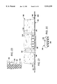
- FIG. 15 is a schematic elevational view of a plurality of layers of grid composite mounted between casting forms for casting of several block systems in a limited space, and in the example shown, on a truck bed or barge.
- FIG. 16 is a schematic illustration of an interconnected block system located under water adjacent to a bridge pier with an anchoring tube secured to a leading edge of the block system.
- FIG. 17 is an enlarged detailed view of the connection of the sand tube shown in FIG. 16 to the leading edge of the block system.
- FIG. 18 is a plan view of an alternative block to be secured to a sheet material matrix according to this invention.
- FIG. 19 is a front elevational view of the block shown in FIG. 18.
- FIG. 20 is a schematic side elevational view of the block shown in FIG. 18 used in a geomattress for erosion control.
- FIG. 21 schematically illustrates the connection of a sheet material matrix to the underside of a concrete block such as shown in FIGS. 18-20 by the use of a plurality of comb-like connector devices engaged within preformed slots extending from the upper surface to the lower surface of the block.
- FIG. 22 is a perspective view of a comb-like connector device as used to secure a section of sheet material matrix to the underside of the block shown in FIG. 21.
- FIG. 23 is an enlarged sectional view of the engagement of the teeth of the fingers of the connector device shown in FIG. 22 in the sidewalls of the slots of the block shown in FIGS. 18 through 21.
- FIG. 24 is a sectional view showing comb-like connector devices engaged in slots in both the lower and upper surfaces of a block for securing sheet material matrices to both surfaces.
- FIG. 25 is a side sectional view illustrating the use of comb-like connector devices to secure underlying matrix sheets to blocks of a pair of geomattresses with an additional comb-like connector devices bridging a gap between adjacent geomattresses sections and securing a length of sheet material to slots in blocks in each of the geomattress sections.
- FIG. 26 is a side view of juxtaposed edge portions of two sections of geomattress with the underlying matrices of the two sections interconnected by a splice plate secured to each edge portion by a bodkin joint.
- FIG. 27 is a side sectional view illustrating the filling of a gap between adjacent blocks in a geomattress formed according to this invention with, for example, shotcrete, hydroseeded soil or staked sod.
- FIG. 28 is a similar view of an interconnected block section according to this invention including upper and lower sheet matrices defining pockets between the blocks which may be filled with fiber, soil or stone fill material.
- FIG. 29 is a view similar to FIG. 28 wherein small sections of a drainage net baffle are located in the pockets formed between adjacent blocks and the sheet material matrices to slow runoff and trap sediment passing over the blocks of the geomattress.
- FIG. 30 is a side view of the use of a geomattress as a cap for contaminated sediments wherein sorptive fill material is carried in the pockets and a geotextile wrap is used to capture the sorptive particles, an optional soil cover being illustrated.
- FIG. 31 is a side view of a geomattress cap for contaminated sediments wherein a geotextile matrix is highly sorptive, or a multi-layer geotextile is provided with sorptive particles therebetween.
- FIG. 32 is a side elevational view of a sling system for lifting a geomattress wherein the strands of one or more sections of uniaxially oriented geogrid sling members are passed between the strands of a geogrid matrix underlying the blocks of a geomattress, with a lifting bar extending between aligned sling members for engagement by heavy equipment such as a crane or the like to lift and place the entire geomattress.
- one form of an interconnected block system or mat or mattress embodying the teachings of the subject invention is generally designated as 20, and includes an underlying, interconnecting, sheet material matrix 22 carrying a plurality of block members 28 formed of concrete or a similar material, rectangular blocks being shown in FIG. 1, although other geometric shapes are equally applicable to this invention.
- the matrix 22 includes a grid-like material formed by a plurality of parallel strands 24 interconnected at nodes or junctions 25 to parallel strands or bars 26 extending perpendicular to strands 24 to define therebetween a multiplicity of apertures 27.
- the grid-like sheet material of the matrix 22 may be an integrally formed uniaxially or biaxially oriented structural geogrid, a bonded composite open mesh structural textile, or for that matter, any grid-like material capable of supporting the plurality of blocks to which the connector elements may be mechanically secured.
- the preferred matrix material for large installations includes an integrally formed, uniaxially oriented, structural geogrid where the bars 26 are unoriented or less oriented and, thus, thicker than, the strands 24 for improved strength.
- a plurality of concrete blocks 28 are secured to the matrix 22 in parallel rows as shown in FIG. 1. Between each row of blocks is a gap 32 which allows bending of the matrix 22 between the blocks to permit the section to assume a non-planar condition for lifting and in use. When the gap between adjacent rows of blocks is large enough, the section may be folded upon itself for lifting and transporting.
- the blocks in juxtaposed rows are preferably staggered or offset by 50% so that water flowing in the direction of arrow 30 would be interrupted to minimize erosion from straight line flow between the blocks.
- the blocks 28 could be positioned and dimensioned to span adjacent sections so as to integrate the underlying matrix material.
- the spacing between juxtaposed blocks 28 is related to the dimensions of the matrix material so as to uniformly position the blocks and balance the system.
- the size and shape of the blocks are site and application specific and can be widely varied without departing from the instant inventive concepts.
- FIG. 1 depicts a block width that may be used for lining an ocean shoreline.
- Other block widths may be used for a boat ramp or for a channel lining application.
- the width and thickness of each concrete block are predicated on the desired coverage, the slope angle and the energy associated with the waves or flow velocity of the water which the concrete system would have to withstand and, therefore, these dimensions can vary.
- the length of each block can vary and may be designed to accommodate the commercially available grid-like sheets of material used to support and interconnect the blocks in the system.
- FIGS. 2 through 4 a bodkin type of mechanical connection between different matrices and a connector element according to this invention is illustrated.
- the underlying, interconnecting matrix 22a is simply a grid-like sheet material, such as an integral uniaxially oriented structural geogrid or the like, in direct contact with the soil 33.
- the matrix 22b is a geocomposite 34 including a geogrid or the like bonded to a geotextile.
- the matrix 22c is a geocomposite including a geogrid or the like bonded to a double-sided drainage composite.
- the connector elements 38 are preferably formed of a grid-like material which may also be formed, for example, of an integral structural geogrid, either uniaxially or biaxially oriented, or a bonded composite open mesh geotextile.
- the mechanical engagement between the matrix 22 and the connector element 38 may take any form, but a bodkin connection, as discussed above, is preferred.
- the grid-like material of the connector element 38 is bent so that, at opposite ends, its strands 40 form a loop which is passed through the openings in the top surface of the grid-like material of the matrix as seen in FIGS. 2-4.
- the connector elements 38 are secured in place by connection or bodkin bars 42 which pass through the loops beneath the grid-like material of the matrix to preclude the connector elements from being disengaged.
- Casting forms (not shown in these Figures) are positioned about each of the upstanding connector elements 38 and concrete or the like is cast in place to capture the connector elements 38 within the thus-formed blocks 28 and thereby mechanically connect the blocks 28 to the upper surface of the matrix 22.
- the strength of the mechanical connection of the blocks 28 to the matrix 22 is provided by the engagement of the concrete-like material of the blocks through openings, apertures or cavities formed by the connector elements 38 alone, or in association with the upper surface of the matrix 22, with no need for the block-forming material to pass through or engage in the apertures of the grid-like material of the matrix.
- This construction permits the matrix to include more than just a geogrid or the like, enabling the use of a geocomposite matrix such as shown at 34 in FIG.
- a geocomposite matrix such as shown at 36 in FIG. 4 may include a double-sided drainage net comprising upper and lower geotextiles 45, 46 with an intermediate layer of geonet 48 sandwiched therebetween.
- Geocomposites such as illustrated at 34 in FIG. 3 are available from Tensar as their GC3320 laminate and drainage composites such as illustrated at 36 in FIG. 4 are available from Tensar as their DC 6205 laminate.
- a geotextile or drainage composite can form the matrix or the upper layer of the matrix, so long as means are provided to secure the connector elements 38 thereto.
- the ability to integrate a geotextile into the matrix using the construction of this invention avoids the need to separately position a geotextile at the work site as is customary to minimize erosion of the soil below a geomattress or the like.
- FIGS. 5-10 Several different embodiments of the construction of the connector element are illustrated in FIGS. 5-10. In each instance a geocomposite matrix of the type shown at 34 in FIG. 3 is illustrated, but it is understood that any of the various matrices disclosed herein may be substituted therefor.
- a connector element 38a is shown for securing a block 28 to the geocomposite matrix 34 which comprises an integral biaxially oriented structural geogrid 52 having a geotextile 54 bonded thereto.
- the geogrid 52 includes strands 56 arranged perpendicular to strands 58 intersecting at nodes 60.
- the connector element 38a is made of a small section of biaxial geogrid 62 having opposite end portions 64 and 66 projecting above the upper surface of the geogrid 52 of the matrix geocomposite 34. Loops formed of the geogrid 62 pass through the openings in the geogrid 52 of the matrix and receive bodkin connector bars 68 to lock the connector element 38a to the geocomposite 34. As shown in FIG. 6, the geogrid 52 and geotextile 56 of the matrix may deflect slightly so as to accommodate the connector bars 68 below the geogrid 52 and above the geotextile 54.
- the block-forming material captures the portions of the geogrid connector 62 projecting above the upper surface of the matrix, namely ends, 64, 66 and U-shaped portion 68, and thereby integrates the block 28 with the geocomposite 34.
- the block-forming material is secured to the connector element 38a, and thus to the geocomposite 34, by frictional engagement with the surface of the material of the connector element and the upper surface of the geocomposite, for most applications such attachment would be inadequate.
- the block-forming material can pass through the apertures of the geogrid 62 to surround and capture the strands of the connector element 38a.
- a large cavity or reservoir 69 is formed between the lower surfaces of the connector element 38a and the upper surfaces of the geocomposite 34 which enables the block-forming material to capture the connector element 38a to secure the block to the geocomposite 34, even if the connector element and the matrix were, for all intents and purposes, imperforate.
- the geocomposite 34 is engaged with a section of a somewhat different configuration of biaxially oriented geogrid connector element 38b which provides a centrally located, generally V-shaped, portion 82 projecting above the upper surface of the geocomposite 34, rather than the U-shaped connecting portion 68 of the previous embodiment.
- the type of material used to form the connector element can be varied significantly without departing from the instant inventive concepts.
- a modified connector element 38c comprises a biaxial geogrid material 84 formed into a circular hoop 90.
- the opposed ends 92 and 94 of the geogrid 84 project above the upper surface of the geocomposite matrix 34 with strands of both ends of the connector element 38b projecting through the geogrid 52 of the matrix at the same location so that a single connector bar 96 may be used to hold the connector element 38b in place.
- the connector element 38b may be slightly compressed, if necessary, prior to block casting so that it is below the overall height of a concrete block 28 to be cast in place on the geocomposite matrix 34.
- the hoop 90 defines an internal cavity 98 for reception of concrete or the like which amplifies the integration of the block-forming material with the connector element and improves the interengagement of the block 28 with the matrix 34.
- a plurality of rectangular blocks 100 and circular blocks 102 are shown on a single geocomposite matrix 34 in FIG. 11. It is understood that in use, the block system of the present invention will generally include all rectangular blocks or all circular blocks, or blocks of other geometries, but, in any event, alternate rows of blocks will be staggered as seen in FIG. 11 to provide lifting gaps between the rows and to interrupt water flow perpendicularly to the lifting gaps.
- FIGS. 12A, 12B, or 12C may be used as an alternative to the connectors shown in FIGS. 12A, 12B, or 12C.
- the strip connector 200 shown in FIG. 12A, strip connector 202 shown in FIG. 12B and strip connector 204 shown in FIG. 12C each include a base or mat 206, 208, 210, respectively.
- the base may be made of plastic or other semi-rigid material and be of an overall length less than the block member which is to be secured to the matrix.
- a plurality of vertically-extending fingers 212 extend perpendicular to the base layer 206.
- a plurality of barbs 216 are provided extending towards base layer 206 at an angle with respect to the main shaft of fingers 212.
- a ball or enlargement 222 is located at the free end 218 of each of the fingers 220 at the free end 218 of each of the fingers 220 at the free end 218 of each of the fingers 220 at the free end 218 of each of the fingers 220.
- the free end 224 of the fingers 228 includes a hook-shaped terminal portion 226 which curves around from the finger 226 in a direction back towards the base layer 210.
- the number of fingers in each strip connector may be more or less than that shown in FIGS. 12A through 12C. It is only essential that the number of fingers is sufficient to retain a block member cast thereon and secure the same to the underlying matrix. Likewise, while specific formations in the nature of barbs, balls and hooks on the free ends of the fingers are shown herein as illustrative, it is only important that the fingers be provided with means to insure that the block-forming material will not readily separate therefrom. Thus, other formations adapted to insure capture and secure engagement of the connector elements with the block-forming material, including even apertures through the fingers (not shown) can be substituted for the illustrated formations.
- a strip connector 230 is shown as including fingers 232 projecting through a matrix material layer 236 with pairs of fingers extending between each bar 238 of the geogrid forming part of the matrix. It is understood that the strip connector 230 may have multiple rows of fingers 232, although only a single row is shown for illustrative purposes.
- the matrix 236 may be simply formed of a geogrid or it may be a geocomposite including a geogrid or the like bonded to a geotextile. The preferred use of a geocomposite facilitates engagement of the strip connector with the matrix, particularly during the block-casting procedure, because the geotextile surrounds and thereby retains the fingers in position.
- a block member 240 is cast upon the matrix 236 so as to engage and surround the portions of the fingers 232 extending above the matrix 236.
- FIGS. 14 and 15 a preferred casting arrangement for forming block members on top of an underlying sheet material matrix 242 is illustrated.
- a connector 244 is anchored to the matrix 242.
- the connector 244 may be of the type shown in FIGS. 2 through 10 or of the type shown in FIGS. 12A through 13.
- a pre-fabricated form or mold 246, in the shape of the to-be-formed block member, is placed about the connector 244.
- the mold may be made, for example, of a unitary piece of dried cast concrete, stiffened thermoplastic or thermoset polymer, or brick.
- the mold 246 is intended to remain permanently in place when the mold is filled with concrete 248, or the like, the concrete adhering to the connector 244 as well as the interior wall 250 of the mold 246. The mold would then become a unitary piece with the to-be-formed block member.
- matrix 262a will include a plurality of the mold members 246a surrounding a connector (not shown). Concrete is then poured into the mold members 246a. While the concrete of layer 252 is curing, a second matrix 262b is placed across the first layer 252 and new mold members 246b are stacked on top of the mold members 246a of the first layer 252.
- the rigidity of the mold members 246a in the first layer is sufficient to support the mold members in the second layer so that a second pouring of concrete can be made while the concrete in the first layer is curing. This process is repeated for layers 256 and 258 until a desired number of layers of matrix material with block members is achieved.
- an interconnected block system 266 including a matrix 268 and plurality of block members 270 is shown located on the floor 272 of a waterway 274.
- the interconnected block system is positioned adjacent to a pier 276 so as to limit the erosion about the base of the pier.
- a woven geotextile tube 276 which is a closed tube with ports for injecting a sand/water slurry.
- a leading edge 276 of the matrix 268 is extended around the tube 276 and secured to itself by a bodkin type of mechanical connection using a connection or bodkin bar 280 which passes through the loops beneath the grid-like material of the matrix 268.
- a section of matrix can surround the tube 276 and be secured to itself as well as to a leading edge portion of the matrix of the block system by a bodkin-type mechanical connection to anchor the additional portion of matrix material to the block system 266. This will anchor the leading edge of the system against movement by water forces in the direction of arrow 282.
- FIGS. 18-25 an alternative interconnected block system is illustrated which preferably utilizes a preformed block 300, shown in detail in FIGS. 18 through 20.
- the block 300 includes an upper surface 302, a lower surface 304, and front wall 306, rear wall 308 and side walls 310, 312 each of which tapers upwardly at an angle of preferably 5° from the lower surface 304 towards the upper surface 302.
- a one-quarter inch chamfered surface 314, surrounds the upper surface 302 of the block and connects the upper surface with the front wall, rear wall and side walls.
- the overall dimensions of the block 300 are preferably about 15.625 inches long, 11.625 inches wide and 3.625 inches deep.
- a plurality of slots are formed in the block 300 for use in securing the block to an interconnecting matrix sheet in a manner to be discussed hereinafter. If the blocks are to be secured only to an underlying matrix, the slots may be formed only in the lower surface 304. If underlying and overlying matrices are to be used as described below, slots may be formed in both the lower surface 304 and the upper surface 302. For ease in manufacture and versatility in use, the slots may extend between the upper surface 302 and the lower surface 304 as illustrated in FIGS. 18-20. Slots 316, 318, 320 and 322 are preferably about five inches long and 0.7 inches wide.
- the slots 316 and 318 extend in a direction parallel to the front and rear walls 306, 308, the edges of the slots 316, 318 located closest to the front and rear walls being preferably spaced approximately two inches from the walls, respectively. Lateral edges of the slots 316, 318 are spaced approximately 5.3 inches from the side walls 310 and 312.
- the slots 320, 322 extend in a direction substantially parallel to the side walls 310, 312 and the edges of the slots 320, 322 located closet to the side walls are preferably spaced approximately 2.6 inches from the side walls, respectively. Lateral edges of the slots 320, 322 are spaced approximately 3.3 inches from the front and rear walls 306, 308.
- slots 324 and 326 Located between the slots 320 and 322 and the side walls 310 and 312 are optional slots 324 and 326 designed to facilitate interconnecting juxtaposed geomattresses in a manner to be described hereinbelow. These slots extend perpendicular to the direction of extension of slots 320 and 322.
- the slots 324, 326 may also extend between the upper surface 302 and the lower surface 304 and preferably have a length of approximately two inches and a width of 0.7 inches.
- the slots 316, 318, 320, 322, 324 and 326 may be formed as recesses in the upper and lower surfaces of the block 300, rather than as through-holes.
- the recesses need only be deep enough to receive the fingers of the connector devices in a frictional fit.
- the preferred block 300 also includes a centrally located, stepped through-aperture 328.
- the lower portion 330 of the aperture 328 has a diameter of approximately 1.5 inches and a height of approximately 2.125 inches.
- An upper portion 332 of the aperture 328 joins the lower portion by a shoulder 334.
- the upper portion 332 has a diameter of approximately three inches and height of approximately 1.5 inches.
- the aperture 328 is used for anchoring of a geomattress, shown schematically at 301 as including an underlying matrix 303 to which a plurality of blocks 300 are attached as discussed below; to a slope 311, embankment, or under water for erosion control, or the like.
- a geomattress shown schematically at 301 as including an underlying matrix 303 to which a plurality of blocks 300 are attached as discussed below; to a slope 311, embankment, or under water for erosion control, or the like.
- an anchoring bolt terminal portions of which are shown in dotted lines at 305, having an engineered earth anchor at the distal end (not shown) is inserted underground.
- the earth anchor is actuated by a slight upward movement of the anchor bolt so as to activate engagement with the earth by an anchor plate.
- a washer 307 is inserted so as to seat on the shoulder 334 of the aperture 328.
- a nut 309 is then applied to the threaded proximal end of the anchor rod until the nut is seated within the section 332 of the aperture 328.
- a portion of the anchor rod projecting above the block 300 may then be removed, if desired, to provide an aesthetically pleasing appearance and to facilitate covering of a plurality of blocks 300 by a grid anchored to the upper surface 302, if desired.
- Interconnected block systems comprising the preformed blocks 300 may be used in the same manner as the embodiments described above.
- the connection of the block 300 to a sheet material matrix, as well as additional uses of the block 300 will be explained with particular reference to FIGS. 21 through 25.
- a block 300 is shown secured to an underlaying sheet material matrix 340.
- the matrix is a geogrid having a plurality of strands 342 and nodes 344 which connect the strands 342 to perpendicularly extending strands or bars.
- the connector devices 346 include a crossbar 348 with a plurality of integral spaced fingers 350 projecting therefrom.
- the fingers 350 preferably include lateral sidewalls 352 which include, proceeding downwardly from crossbar 348, a plurality of spiked projections 354.
- the projections 354 extend approximately 1/16 of an inch beyond the side walls 352 of the fingers 350.
- Each spiked projection 354 has an overall height of approximately 3/16 of an inch.
- the spike projection 354 is schematically shown engaging a sidewall 356 of slot 320. Due to the resilient nature of the material of the connector device 346, the spike projections 354 are driven inwardly along the length of the sidewalls 356 of the slots for frictional engagement with the sidewalls. By the angle of inclination of the spike projections 354, it is possible to drive the fingers 350 into the slots whereas considerable force would be required to extricate the connector devices 346 from the slots.
- the fingers of the connector devices are spaced a multiple of the spacing between apertures of the grid matrix 340 interconnecting the blocks 300. Only three connector devices 346 are seen in FIG. 21, although it is understood that preferably a connector devices would be located in each of the slots 316, 318, 320 and 322 so as to completely secure the blocks to the grid.
- FIG. 21 An optional geotextile 358 is shown in FIG. 21 underlying the grid 340 and the crossbar 348 of the connector devices 346 to provide the same advantages as the use of a geocomposite in the previous embodiments.
- the connector devices could be driven through the geotextile, if desired.
- an optional top grid 362 is secured to the block 300 by additional connector devices, one of which is shown at 360.
- additional connector devices one of which is shown at 360.
- the use of both underlying and overlying interconnecting grid matrices provides a number of advantages in addition to increasing the strength of the geomattress.
- a plurality of blocks 364, 366 representative of a plurality of rows of blocks secured to a matrix in a geomattress, define gaps or pockets 368 between the blocks and bottom and top layer of interconnecting grid 370, 374, respectively.
- the pockets 368 may be filled with fiber (mulch) or an aggregate such soil or stone 372.
- the fill material provides increased erosion resistance by providing an undulating path for water passing over the upper surfaces of the blocks. Additionally, the fill material may provide a growing medium to encourage vegetation to root and further resist erosion.
- a gap or pocket 376 is shown between blocks 378 and 380 and the lower upper grids 382, 384.
- a short section of drainage net 386 or the like is bent along a horizontally extending axis so that its leading edge 388 and trailing edge 390 engage the blocks 378 and 380.
- the net may be connected to the upper grid 384 by a cable tie to retain its position.
- the drainage net 386 may be similar to the net material sandwiched between two layers of geofabric in drainage composite DC6205 available from The Tensar Corporation as previously described.
- Water passing downwardly over the upper surface of block 380 will be caused to pass through the upper grid 384 and down onto the drainage net 386. This will slow the speed of the runoff water and cause sediment in the water to be trapped by the drainage net 386 in the gap 376. Build up of sediment will foster growth of vegetation and provide additional resistance against erosion.
- gaps 392 between blocks such as shown at 394 and 396 may be filled with shotcrete, hydroseeded soil or staked to improve the effectiveness of a geomattress formed according to this invention even without the upper layer of grid.
- Earth staples 402 may be used to anchor the fill material 400 in the gap 392, and to anchor the geomattress to an underlying base material.
- the pockets 490 between blocks 500 and lower and upper interconnecting grid matrices 502, 504 are filled with a sorptive material 506, either prior to, or after securing the upper layer of geogrid 504 to the blocks.
- the sorptive fill material may, for example, be activated carbon particles which fill the gaps surrounding the blocks in the geomattress. Since such materials are commonly light weight, of a particle size smaller than the apertures in the grid-like interconnecting matrices, and buoyant, the entire geomattress may be sealed in a geotextile wrap 506 to keep the sorptive material from floating away when the geomattress is used underwater.
- the geotextile wrap 506 is of an integral form or of pieces which, when assembled, cover the top, bottom, front edge, rear edge and side walls of a formed geomattress.
- the thus-formed geomattress may then be used to cap a contaminated sediment bed 508 with an optional cover layer of soil 510.
- contaminants escaping from the sediment bed 508 will pass through geotextile located below the blocks 500 to be absorbed or adsorbed by the sorptive fill material 506.
- the close proximity of the sorptive fill material to the contaminated sediment provides for an effective treatment of contaminant materials as they are released into the surrounding subaqueous environment.
- a contaminated sediment bed 520 may be covered by a sorptive geotextile layer 522 or a plurality of geotextile layers trapping a sorptive material between them, which is positioned below a geomattress 524 including concrete blocks 526 attached on one side to a geogrid layer 528.
- Continuous filament, non-woven, needle-punched geotextile materials are commercially available which have been formulated and/or treated to preferentially absorb or adsorb hydrocarbons and other such contaminants from an aqueous environment and such materials may form the layer 522.
- An optional soil cover layer 530 covers the geomattress 524 and fills the gap between adjacent blocks 526.
- Juxtaposed sections of geomattress may be integrated by a variety of splicing techniques according to this invention.
- two separate geomattress sections 404 and 406 are aligned adjacent to each other.
- the terminal edge portions 408 of grid matrix 410 of the section 404 underlies overlapping terminal edge portions 412 of grid matrix 414 of section 406.
- edge portions of geotextile 416 associated with grid 410 may be positioned to underlie edge portions of geotextile 418 associated with grid 414.
- connector 420 secure the grid 410 to the lower surface of block 422 and connectors 424 secures grid 414 to the lower surface of block 426.
- the gap 428 formed between the blocks 422 and 426 may be filled with fill material as in FIGS. 28 and 29.
- an elongated splicing strip 430 of grid material extends across the gap and over the upper surfaces of the blocks 422, 426.
- a plurality of connectors 432 having spaced apart fingers 434 extend between the openings of the grid and into, at each end, one of the optional slots 324 and 326 provided in the preformed blocks as shown in FIG. 18.
- FIG. 26 Another system for connecting adjacent geomattress sections 436, 438, is shown in FIG. 26.
- terminal end portions 440 of grid section 442 carrying blocks such as shown at 466 are juxtaposed to terminal end portions 444 of grid section 446 carrying blocks 468.
- Optional underlying layers of geotextile 448, 450 may be present as in previous embodiments.
- the terminal end portions 440, 444 of the grids 442, 446, respectively are joined by a grid splice plate 452.
- the strands of the end portions 454, 456 of the splice plate 452 adjacent the ends portions 440, 444, respectively, of the grids 442, 446 are bent so that they project between the strands of the grid as is known in the formation of a bodkin joint.
- Connection rods 462, 464 are inserted between interleaved portions of grid material to preclude retraction of these portions.
- a joint between the adjacent geomattress sections 436, 438 is thereby formed.
- an overlying splicing strip may also be secured between the blocks 466 and 468 to close the gap 470 between the geomattress sections 436 and 438, if desired.
- a lifting hoop 472 may be formed by bending a section of, preferably, uniaxially oriented integral geogrid, such that its strands pass between the strands of a terminal portion 474 of a length of geogrid 476 extending laterally from blocks 478 located at the edge of the geomattress to be lifted.
- the bars 480 at the ends of the lifting hoop 472 are restrained by the strands of the section 474 of the grid 476.
- the entire mattress can be lifted by the bar 482. Due to the uniaxial orientation of the strands of the lifting hoop 472, the weight of a single or a plurality of sections of a geomattress may be lifted by the capturing of the lifting bar 482 within the strands of the lifting hoop 472.
Landscapes
- Engineering & Computer Science (AREA)
- General Engineering & Computer Science (AREA)
- Environmental & Geological Engineering (AREA)
- Civil Engineering (AREA)
- Structural Engineering (AREA)
- Ocean & Marine Engineering (AREA)
- Mechanical Engineering (AREA)
- Life Sciences & Earth Sciences (AREA)
- General Life Sciences & Earth Sciences (AREA)
- Mining & Mineral Resources (AREA)
- Paleontology (AREA)
- Revetment (AREA)
Abstract
Description
Claims (33)
Priority Applications (1)
| Application Number | Priority Date | Filing Date | Title |
|---|---|---|---|
| US08/763,948 US5911539A (en) | 1996-07-09 | 1996-12-11 | Interconnected block system |
Applications Claiming Priority (3)
| Application Number | Priority Date | Filing Date | Title |
|---|---|---|---|
| US67718996A | 1996-07-09 | 1996-07-09 | |
| US08/730,600 US5823709A (en) | 1996-07-09 | 1996-10-15 | Interconnected block system |
| US08/763,948 US5911539A (en) | 1996-07-09 | 1996-12-11 | Interconnected block system |
Related Parent Applications (1)
| Application Number | Title | Priority Date | Filing Date |
|---|---|---|---|
| US08/730,600 Continuation-In-Part US5823709A (en) | 1996-07-09 | 1996-10-15 | Interconnected block system |
Publications (1)
| Publication Number | Publication Date |
|---|---|
| US5911539A true US5911539A (en) | 1999-06-15 |
Family
ID=46253223
Family Applications (1)
| Application Number | Title | Priority Date | Filing Date |
|---|---|---|---|
| US08/763,948 Expired - Lifetime US5911539A (en) | 1996-07-09 | 1996-12-11 | Interconnected block system |
Country Status (1)
| Country | Link |
|---|---|
| US (1) | US5911539A (en) |
Cited By (48)
| Publication number | Priority date | Publication date | Assignee | Title |
|---|---|---|---|---|
| US6287054B1 (en) | 2000-05-18 | 2001-09-11 | Atlantech International Inc. | Plantable wall block assembly and retaining wall formed therefrom |
| US6416253B1 (en) * | 2000-05-02 | 2002-07-09 | Lee Masonry Products, Llc | Abrasive resistant open cell articulated seabed mat |
| US20030029114A1 (en) * | 2001-07-12 | 2003-02-13 | Macdonald Robert A. | Multi-channel retaining wall block and system |
| US6536994B2 (en) | 2001-07-12 | 2003-03-25 | Keystone Retaining Wall Systems, Inc. | Grooved retaining wall block and system |
| US20030066259A1 (en) * | 2001-09-10 | 2003-04-10 | Sudweeks Dan L. | Fastener system and method for attaching manufactured brick or stone to a surface |
| US6615561B2 (en) | 2001-06-07 | 2003-09-09 | Keystone Retaining Wall Systems, Inc. | Retaining wall block |
| US20040265060A1 (en) * | 2001-10-26 | 2004-12-30 | Lee Keun-Hee | Method for constructing scour protection of bridge and stabilization of stream bed using block mat |
| US20050158122A1 (en) * | 2002-04-19 | 2005-07-21 | Keun Hee Lee | Method for contructing check dam or fire prevention dam using gear-type block |
| US20060102565A1 (en) * | 2004-11-12 | 2006-05-18 | Alford Paul W | System and method for dewatering sludge, slurry or sediment |
| US7097390B1 (en) | 2005-06-16 | 2006-08-29 | Mega, Inc. | Fine-grained fill reinforcing apparatus and method |
| US20060191224A1 (en) * | 2005-02-25 | 2006-08-31 | Brian Iske | Device for post-installation in-situ barrier creation and method of use thereof |
| US20060222462A1 (en) * | 2001-04-11 | 2006-10-05 | Sheahan Thomas C | Method of containing and at least partially remediating contaminants in soils, including sediments |
| US20060236617A1 (en) * | 2005-04-26 | 2006-10-26 | Shih-Yin Chen | Latticed net stretching and fixing structure |
| US20070199265A1 (en) * | 2005-02-25 | 2007-08-30 | W.R. Grace & Co.-Conn. | Device For In-Situ Barrier |
| US7278803B1 (en) | 2006-09-05 | 2007-10-09 | Jeff M Moreau | Corrugated asymmetrical retaining wall panel |
| US20080169674A1 (en) * | 2007-01-17 | 2008-07-17 | Larry Robert Giles | Modular cargo containment wall system |
| US20080170913A1 (en) * | 2006-10-23 | 2008-07-17 | Moreau Jeff M | Seawall connector for attachment of geogrid material |
| USD575414S1 (en) | 2007-06-11 | 2008-08-19 | Armortec Inc. | Revetment block |
| USD580561S1 (en) | 2007-10-05 | 2008-11-11 | Armortec, Llc | Pad for a seabed mat |
| USD582569S1 (en) | 2006-08-23 | 2008-12-09 | Jeff M Moreau | Sheet piling |
| US20090092447A1 (en) * | 2007-10-08 | 2009-04-09 | Armortec, Inc. | Non-abrasive pad for an articulated seabed mat |
| EP2163320A1 (en) * | 2008-09-15 | 2010-03-17 | Amcol International Corporation | Contaminant-reactive gabion/geocomposite article and method of manufacture and use |
| US20100080656A1 (en) * | 2008-09-26 | 2010-04-01 | Palmer Andrew C | Systems and methods for protecting subterranean structures |
| US20100111611A1 (en) * | 2007-04-30 | 2010-05-06 | Amcol International Corporation | Contaminant-reactive gabion cage or grid structure and method of manufacture and use |
| WO2011146545A1 (en) | 2010-05-17 | 2011-11-24 | Armaterra, Inc. | Tire georeinforcing system |
| US20120023857A1 (en) * | 2010-07-30 | 2012-02-02 | Redi-Rock International, Llc | Process For Casting Concrete Wall Blocks For Use With Geogrid |
| US8622659B2 (en) | 2010-03-04 | 2014-01-07 | Keystone Retaining Wall Systems Llc | Retaining wall block system |
| CN105297748A (en) * | 2015-11-13 | 2016-02-03 | 中铁二院工程集团有限责任公司 | Ice water accumulation cutting slope reinforcement and protection structure |
| US9644334B2 (en) | 2013-08-19 | 2017-05-09 | Stable Concrete Structures, Inc. | Methods of and systems for controlling water flow, breaking water waves and reducing surface erosion along rivers, streams, waterways and coastal regions |
| WO2017136518A1 (en) * | 2016-02-02 | 2017-08-10 | Tensar International Corporation | Geosynthetic reinforced wall panels comprising soil reinforcing members |
| US9951491B2 (en) * | 2016-05-18 | 2018-04-24 | Tsun Chow | Bricks and a method for using such bricks to build dikes in water |
| US10053832B2 (en) | 2011-01-10 | 2018-08-21 | Stable Concrete Structures, Inc. | Molded concrete U-wall construction block employing a metal reinforcement cage having stem reinforcement portions with open apertures formed therein for multiple purposes |
| US10161094B2 (en) * | 2016-03-23 | 2018-12-25 | Motz Enterprises, Inc. | Erosion-preventing laminate mat and assembly system |
| WO2019106380A1 (en) * | 2017-12-01 | 2019-06-06 | Geocontec Limited | Connector for geogrids |
| US10392764B1 (en) * | 2017-11-21 | 2019-08-27 | Premier Concrete Products, Inc. | Revetment mat |
| US10684112B2 (en) * | 2017-09-22 | 2020-06-16 | Shandong University | Structure for monitoring stability of existing subgrade/slope and construction method thereof |
| CN111560919A (en) * | 2020-06-01 | 2020-08-21 | 李飞 | Slope protection assembly easy to mount and dismount and used for hydraulic and hydroelectric engineering |
| US10814528B2 (en) | 2016-02-19 | 2020-10-27 | Motz Enterprises, Inc. | Flexible mat forming system and method |
| CN113073607A (en) * | 2021-03-29 | 2021-07-06 | 四川宇硕建筑工程集团有限公司 | Hydraulic engineering slope protection structure |
| US11073017B2 (en) | 2017-05-10 | 2021-07-27 | Gcp Applied Technologies Inc. | In-situ barrier device with internal injection conduit |
| US11097446B2 (en) | 2019-06-13 | 2021-08-24 | Motz Enterprises, Inc. | System and method for making tied block mat with border |
| RU2756651C1 (en) * | 2021-03-10 | 2021-10-04 | Федеральное государственное автономное образовательное учреждение высшего образования «Северный (Арктический) федеральный университет имени М. В. Ломоносова» | Connector for flat geogrid |
| US11198231B2 (en) | 2016-02-19 | 2021-12-14 | Motz Enterprises, Inc. | Process and system for making an erosion control mat |
| US20220065221A1 (en) * | 2020-08-28 | 2022-03-03 | Rzeszów University of Technology | Block for geotechnical applications, a method of making a block for geotechnical applications and a method of making a structure using a block for geotechnical applications |
| US11345065B2 (en) | 2016-02-19 | 2022-05-31 | Motz Enterprises, Inc. | Flexible mat forming system and method |
| CN114753306A (en) * | 2022-04-25 | 2022-07-15 | 中交上海航道勘察设计研究院有限公司 | Ballast block unit and application thereof |
| US11525258B2 (en) * | 2020-12-07 | 2022-12-13 | Pravin Nanayakkara | Masonry block anchor system |
| JP2024020802A (en) * | 2022-08-02 | 2024-02-15 | 前田工繊株式会社 | Weed control block mat and its manufacturing method |
Citations (25)
| Publication number | Priority date | Publication date | Assignee | Title |
|---|---|---|---|---|
| US869566A (en) * | 1906-05-29 | 1907-10-29 | Frederic W Hawkes | Riprap. |
| US1071091A (en) * | 1912-08-26 | 1913-08-26 | Harry E Rogers | Flexible revetment. |
| US2092183A (en) * | 1935-12-02 | 1937-09-07 | Rehfeld George William | Mat for protecting banks of streams |
| US2876628A (en) * | 1956-07-02 | 1959-03-10 | Jr George F Dixon | Rapid sinking articulated revetment |
| US3096621A (en) * | 1959-01-20 | 1963-07-09 | Grenobloise Etude Appl | Artificial blocks for the protection of hydraulic structures |
| US3597928A (en) * | 1967-12-22 | 1971-08-10 | Jan Carel Pilaar | Erosion control |
| US3601015A (en) * | 1969-05-22 | 1971-08-24 | Lorin H Kilstofte | Composite spacer seat for reinforcing fabric and bars |
| US3702093A (en) * | 1970-04-03 | 1972-11-07 | Bekaert Cockerill Nv Sa | Construction of concrete road with expansion joints |
| DE2123523A1 (en) * | 1971-05-12 | 1972-11-23 | Roberti, Lorenzo, Fano (Italien) | Bank reinforcement |
| US3922865A (en) * | 1972-10-06 | 1975-12-02 | Aannemers Comb Zinkwerke | Mattress, method of sinking a mattress and vessel suitable for use in said method |
| US4370075A (en) * | 1980-10-28 | 1983-01-25 | Nicolon Corporation | Revetment grids and mats |
| US4374798A (en) * | 1978-10-16 | 1983-02-22 | P.L.G. Research | Production of plastic mesh structure |
| US4417828A (en) * | 1980-09-15 | 1983-11-29 | Nicolon B.V. | Erosion protection mat |
| US4436447A (en) * | 1980-09-17 | 1984-03-13 | Terrafix Erosion Control Products, Inc. | Erosion control blocks |
| US4449847A (en) * | 1982-09-27 | 1984-05-22 | Nicolon Corporation | Revetment panel |
| US4502815A (en) * | 1982-09-27 | 1985-03-05 | Nicolon Corporation | Revetment panel methods |
| US4530622A (en) * | 1982-12-23 | 1985-07-23 | P.L.G. Research Limited | Retaining fill in a geotechnical structure |
| US4726708A (en) * | 1985-12-17 | 1988-02-23 | Officine Maccaferri S.P.A. | Mattress-type gabion for producing protective covering structures to be used on soil surfaces subject to erosion |
| US4815892A (en) * | 1987-01-21 | 1989-03-28 | Netlon Limited | Drainage material and drainage core for a drainage system |
| US5108222A (en) * | 1990-09-11 | 1992-04-28 | Jansson Jan E | Articulated, predominantly concrete mat |
| US5273804A (en) * | 1988-11-07 | 1993-12-28 | Netlon Limited | Reinforcement for reinforcing a paved surface |
| EP0608036A1 (en) * | 1993-01-21 | 1994-07-27 | Hendrik Voogt | Block mattress for the protection of slopes, berms and the like |
| US5342141A (en) * | 1993-03-10 | 1994-08-30 | Close Darrell R | Movable surface paving apparatus and method for using the same |
| US5540525A (en) * | 1994-06-06 | 1996-07-30 | The Tensar Corporation | Modular block retaining wall system and method of constructing same |
| US5595460A (en) * | 1994-06-06 | 1997-01-21 | The Tensar Corporation | Modular block retaining wall system and method of constructing same |
-
1996
- 1996-12-11 US US08/763,948 patent/US5911539A/en not_active Expired - Lifetime
Patent Citations (26)
| Publication number | Priority date | Publication date | Assignee | Title |
|---|---|---|---|---|
| US869566A (en) * | 1906-05-29 | 1907-10-29 | Frederic W Hawkes | Riprap. |
| US1071091A (en) * | 1912-08-26 | 1913-08-26 | Harry E Rogers | Flexible revetment. |
| US2092183A (en) * | 1935-12-02 | 1937-09-07 | Rehfeld George William | Mat for protecting banks of streams |
| US2876628A (en) * | 1956-07-02 | 1959-03-10 | Jr George F Dixon | Rapid sinking articulated revetment |
| US3096621A (en) * | 1959-01-20 | 1963-07-09 | Grenobloise Etude Appl | Artificial blocks for the protection of hydraulic structures |
| US3597928A (en) * | 1967-12-22 | 1971-08-10 | Jan Carel Pilaar | Erosion control |
| US3601015A (en) * | 1969-05-22 | 1971-08-24 | Lorin H Kilstofte | Composite spacer seat for reinforcing fabric and bars |
| US3702093A (en) * | 1970-04-03 | 1972-11-07 | Bekaert Cockerill Nv Sa | Construction of concrete road with expansion joints |
| DE2123523A1 (en) * | 1971-05-12 | 1972-11-23 | Roberti, Lorenzo, Fano (Italien) | Bank reinforcement |
| US3922865A (en) * | 1972-10-06 | 1975-12-02 | Aannemers Comb Zinkwerke | Mattress, method of sinking a mattress and vessel suitable for use in said method |
| US4374798A (en) * | 1978-10-16 | 1983-02-22 | P.L.G. Research | Production of plastic mesh structure |
| US4417828A (en) * | 1980-09-15 | 1983-11-29 | Nicolon B.V. | Erosion protection mat |
| US4436447A (en) * | 1980-09-17 | 1984-03-13 | Terrafix Erosion Control Products, Inc. | Erosion control blocks |
| US4370075A (en) * | 1980-10-28 | 1983-01-25 | Nicolon Corporation | Revetment grids and mats |
| US4449847A (en) * | 1982-09-27 | 1984-05-22 | Nicolon Corporation | Revetment panel |
| US4502815A (en) * | 1982-09-27 | 1985-03-05 | Nicolon Corporation | Revetment panel methods |
| US4530622A (en) * | 1982-12-23 | 1985-07-23 | P.L.G. Research Limited | Retaining fill in a geotechnical structure |
| US4726708A (en) * | 1985-12-17 | 1988-02-23 | Officine Maccaferri S.P.A. | Mattress-type gabion for producing protective covering structures to be used on soil surfaces subject to erosion |
| US4815892A (en) * | 1987-01-21 | 1989-03-28 | Netlon Limited | Drainage material and drainage core for a drainage system |
| US4815892B1 (en) * | 1987-01-21 | 1997-01-07 | Netlon Ltd | Drainage material and drainage core for a drainage system |
| US5273804A (en) * | 1988-11-07 | 1993-12-28 | Netlon Limited | Reinforcement for reinforcing a paved surface |
| US5108222A (en) * | 1990-09-11 | 1992-04-28 | Jansson Jan E | Articulated, predominantly concrete mat |
| EP0608036A1 (en) * | 1993-01-21 | 1994-07-27 | Hendrik Voogt | Block mattress for the protection of slopes, berms and the like |
| US5342141A (en) * | 1993-03-10 | 1994-08-30 | Close Darrell R | Movable surface paving apparatus and method for using the same |
| US5540525A (en) * | 1994-06-06 | 1996-07-30 | The Tensar Corporation | Modular block retaining wall system and method of constructing same |
| US5595460A (en) * | 1994-06-06 | 1997-01-21 | The Tensar Corporation | Modular block retaining wall system and method of constructing same |
Cited By (74)
| Publication number | Priority date | Publication date | Assignee | Title |
|---|---|---|---|---|
| US6416253B1 (en) * | 2000-05-02 | 2002-07-09 | Lee Masonry Products, Llc | Abrasive resistant open cell articulated seabed mat |
| US6287054B1 (en) | 2000-05-18 | 2001-09-11 | Atlantech International Inc. | Plantable wall block assembly and retaining wall formed therefrom |
| US7128498B2 (en) * | 2001-04-11 | 2006-10-31 | The United States Of America As Represented By The Secretary Of The Army | Method of containing and at least partially remediating contaminants in soils, including sediments |
| US20060222462A1 (en) * | 2001-04-11 | 2006-10-05 | Sheahan Thomas C | Method of containing and at least partially remediating contaminants in soils, including sediments |
| US6615561B2 (en) | 2001-06-07 | 2003-09-09 | Keystone Retaining Wall Systems, Inc. | Retaining wall block |
| US6709201B2 (en) | 2001-07-12 | 2004-03-23 | Keystone Retaining Wall Systems, Inc. | Grooved retaining wall block and system |
| US6854231B2 (en) | 2001-07-12 | 2005-02-15 | Keystone Retaining Wall Systems, Inc. | Multi-channel retaining wall block and system |
| US6912823B2 (en) | 2001-07-12 | 2005-07-05 | Keystone Retaining Wall Systems, Inc. | Multi-channel retaining wall block and system |
| US6536994B2 (en) | 2001-07-12 | 2003-03-25 | Keystone Retaining Wall Systems, Inc. | Grooved retaining wall block and system |
| US20030029114A1 (en) * | 2001-07-12 | 2003-02-13 | Macdonald Robert A. | Multi-channel retaining wall block and system |
| US20030066259A1 (en) * | 2001-09-10 | 2003-04-10 | Sudweeks Dan L. | Fastener system and method for attaching manufactured brick or stone to a surface |
| US20040265060A1 (en) * | 2001-10-26 | 2004-12-30 | Lee Keun-Hee | Method for constructing scour protection of bridge and stabilization of stream bed using block mat |
| US20050158122A1 (en) * | 2002-04-19 | 2005-07-21 | Keun Hee Lee | Method for contructing check dam or fire prevention dam using gear-type block |
| US20060102565A1 (en) * | 2004-11-12 | 2006-05-18 | Alford Paul W | System and method for dewatering sludge, slurry or sediment |
| US20090274518A1 (en) * | 2005-02-25 | 2009-11-05 | Brian Iske | Method for Post-Installation In-Situ Barrier Creation |
| US8291668B2 (en) | 2005-02-25 | 2012-10-23 | W. R. Grace & Co.-Conn. | Device for in-situ barrier |
| US20060191224A1 (en) * | 2005-02-25 | 2006-08-31 | Brian Iske | Device for post-installation in-situ barrier creation and method of use thereof |
| US7584581B2 (en) | 2005-02-25 | 2009-09-08 | Brian Iske | Device for post-installation in-situ barrier creation and method of use thereof |
| US20070199265A1 (en) * | 2005-02-25 | 2007-08-30 | W.R. Grace & Co.-Conn. | Device For In-Situ Barrier |
| US7565779B2 (en) * | 2005-02-25 | 2009-07-28 | W. R. Grace & Co.-Conn. | Device for in-situ barrier |
| US20090126291A1 (en) * | 2005-02-25 | 2009-05-21 | Brian Iske | Device for Post-Installation In-Situ Barrier Creation |
| US7836650B2 (en) | 2005-02-25 | 2010-11-23 | Brian Iske | Device for post-installation in-situ barrier creation |
| US7900418B2 (en) | 2005-02-25 | 2011-03-08 | Brian Iske | Method for post-installation in-situ barrier creation |
| US20060236617A1 (en) * | 2005-04-26 | 2006-10-26 | Shih-Yin Chen | Latticed net stretching and fixing structure |
| US7097390B1 (en) | 2005-06-16 | 2006-08-29 | Mega, Inc. | Fine-grained fill reinforcing apparatus and method |
| US7314336B2 (en) | 2005-06-16 | 2008-01-01 | Mega, Inc. | Fine-grained fill reinforcing apparatus and method |
| US20070041793A1 (en) * | 2005-06-16 | 2007-02-22 | Moss Arthur L | Fine-grained fill reinforcing apparatus and method |
| USD582569S1 (en) | 2006-08-23 | 2008-12-09 | Jeff M Moreau | Sheet piling |
| US7278803B1 (en) | 2006-09-05 | 2007-10-09 | Jeff M Moreau | Corrugated asymmetrical retaining wall panel |
| US20080170913A1 (en) * | 2006-10-23 | 2008-07-17 | Moreau Jeff M | Seawall connector for attachment of geogrid material |
| US20080169674A1 (en) * | 2007-01-17 | 2008-07-17 | Larry Robert Giles | Modular cargo containment wall system |
| US20100111611A1 (en) * | 2007-04-30 | 2010-05-06 | Amcol International Corporation | Contaminant-reactive gabion cage or grid structure and method of manufacture and use |
| US8262318B2 (en) | 2007-04-30 | 2012-09-11 | Amcol International Corporation | Contaminant-reactive gabion cage or grid structure and method of manufacture and use |
| USD575414S1 (en) | 2007-06-11 | 2008-08-19 | Armortec Inc. | Revetment block |
| USD580561S1 (en) | 2007-10-05 | 2008-11-11 | Armortec, Llc | Pad for a seabed mat |
| US20090092447A1 (en) * | 2007-10-08 | 2009-04-09 | Armortec, Inc. | Non-abrasive pad for an articulated seabed mat |
| EP2163320A1 (en) * | 2008-09-15 | 2010-03-17 | Amcol International Corporation | Contaminant-reactive gabion/geocomposite article and method of manufacture and use |
| US20100080656A1 (en) * | 2008-09-26 | 2010-04-01 | Palmer Andrew C | Systems and methods for protecting subterranean structures |
| US8215870B2 (en) * | 2008-09-26 | 2012-07-10 | Palmer Andrew C | Systems and methods for protecting subterranean structures |
| US8622659B2 (en) | 2010-03-04 | 2014-01-07 | Keystone Retaining Wall Systems Llc | Retaining wall block system |
| US9028175B2 (en) | 2010-03-04 | 2015-05-12 | Keystone Retaining Wall Systems Llc | Retaining wall block system |
| WO2011146545A1 (en) | 2010-05-17 | 2011-11-24 | Armaterra, Inc. | Tire georeinforcing system |
| US9051707B2 (en) | 2010-05-17 | 2015-06-09 | Armaterra, Inc. | Tire georeinforcing system |
| US8485760B2 (en) | 2010-05-17 | 2013-07-16 | Armaterra, Inc. | Tire georeinforcing system |
| US8876438B2 (en) * | 2010-07-30 | 2014-11-04 | Redi-Rock International, Llc | Process for casting concrete wall blocks for use with geogrid |
| US20120023857A1 (en) * | 2010-07-30 | 2012-02-02 | Redi-Rock International, Llc | Process For Casting Concrete Wall Blocks For Use With Geogrid |
| US10443206B2 (en) | 2011-01-10 | 2019-10-15 | Stable Concrete Structures, Inc. | Block reinforcement cage having stem reinforcement portions with open apertures formed therein, for use in reinforcing a molded concrete U-wall construction block |
| US10053832B2 (en) | 2011-01-10 | 2018-08-21 | Stable Concrete Structures, Inc. | Molded concrete U-wall construction block employing a metal reinforcement cage having stem reinforcement portions with open apertures formed therein for multiple purposes |
| US9644334B2 (en) | 2013-08-19 | 2017-05-09 | Stable Concrete Structures, Inc. | Methods of and systems for controlling water flow, breaking water waves and reducing surface erosion along rivers, streams, waterways and coastal regions |
| CN105297748B (en) * | 2015-11-13 | 2018-11-23 | 中铁二院工程集团有限责任公司 | Ice water deposit cut slope reinforcement protection structure |
| CN105297748A (en) * | 2015-11-13 | 2016-02-03 | 中铁二院工程集团有限责任公司 | Ice water accumulation cutting slope reinforcement and protection structure |
| US10865540B2 (en) | 2016-02-02 | 2020-12-15 | Tensar International Corporation | Geosynthetic reinforced wall panels comprising soil reinforcing members |
| WO2017136518A1 (en) * | 2016-02-02 | 2017-08-10 | Tensar International Corporation | Geosynthetic reinforced wall panels comprising soil reinforcing members |
| EP3411530A4 (en) * | 2016-02-02 | 2019-03-06 | Tensar International Corporation | ENHANCED GEOSYNTHETIC WALL PANELS COMPRISING SOIL REINFORCING ELEMENTS |
| US11198231B2 (en) | 2016-02-19 | 2021-12-14 | Motz Enterprises, Inc. | Process and system for making an erosion control mat |
| US11565446B2 (en) | 2016-02-19 | 2023-01-31 | Motz Enterprises, Inc. | Hopper for a flexible mat forming system |
| US11345065B2 (en) | 2016-02-19 | 2022-05-31 | Motz Enterprises, Inc. | Flexible mat forming system and method |
| US10814528B2 (en) | 2016-02-19 | 2020-10-27 | Motz Enterprises, Inc. | Flexible mat forming system and method |
| USRE49482E1 (en) * | 2016-03-23 | 2023-04-04 | Motz Enterprises, Inc. | Erosion-preventing laminate mat and assembly system |
| US10161094B2 (en) * | 2016-03-23 | 2018-12-25 | Motz Enterprises, Inc. | Erosion-preventing laminate mat and assembly system |
| US9951491B2 (en) * | 2016-05-18 | 2018-04-24 | Tsun Chow | Bricks and a method for using such bricks to build dikes in water |
| US11073017B2 (en) | 2017-05-10 | 2021-07-27 | Gcp Applied Technologies Inc. | In-situ barrier device with internal injection conduit |
| US10684112B2 (en) * | 2017-09-22 | 2020-06-16 | Shandong University | Structure for monitoring stability of existing subgrade/slope and construction method thereof |
| US10392764B1 (en) * | 2017-11-21 | 2019-08-27 | Premier Concrete Products, Inc. | Revetment mat |
| WO2019106380A1 (en) * | 2017-12-01 | 2019-06-06 | Geocontec Limited | Connector for geogrids |
| US11097446B2 (en) | 2019-06-13 | 2021-08-24 | Motz Enterprises, Inc. | System and method for making tied block mat with border |
| CN111560919A (en) * | 2020-06-01 | 2020-08-21 | 李飞 | Slope protection assembly easy to mount and dismount and used for hydraulic and hydroelectric engineering |
| US20220065221A1 (en) * | 2020-08-28 | 2022-03-03 | Rzeszów University of Technology | Block for geotechnical applications, a method of making a block for geotechnical applications and a method of making a structure using a block for geotechnical applications |
| US12158135B2 (en) * | 2020-08-28 | 2024-12-03 | Rzeszów University of Technology | Block for geotechnical applications |
| US11525258B2 (en) * | 2020-12-07 | 2022-12-13 | Pravin Nanayakkara | Masonry block anchor system |
| RU2756651C1 (en) * | 2021-03-10 | 2021-10-04 | Федеральное государственное автономное образовательное учреждение высшего образования «Северный (Арктический) федеральный университет имени М. В. Ломоносова» | Connector for flat geogrid |
| CN113073607A (en) * | 2021-03-29 | 2021-07-06 | 四川宇硕建筑工程集团有限公司 | Hydraulic engineering slope protection structure |
| CN114753306A (en) * | 2022-04-25 | 2022-07-15 | 中交上海航道勘察设计研究院有限公司 | Ballast block unit and application thereof |
| JP2024020802A (en) * | 2022-08-02 | 2024-02-15 | 前田工繊株式会社 | Weed control block mat and its manufacturing method |
Similar Documents
| Publication | Publication Date | Title |
|---|---|---|
| US5911539A (en) | Interconnected block system | |
| US5823709A (en) | Interconnected block system | |
| US7314336B2 (en) | Fine-grained fill reinforcing apparatus and method | |
| US5632571A (en) | Concrete geomattress | |
| AU761614B2 (en) | Tyre foundation structure | |
| SA94140670B1 (en) | Reinforced cell material | |
| CN107354911A (en) | A kind of ecological flexible geogrid reinforcement Wharf Construction method | |
| JP5921857B2 (en) | Slope protection structure in which honeycomb-shaped three-dimensional solid cell structures are stacked vertically | |
| KR20160027646A (en) | Bank and method for the same using the geotextiles tube law for preventing coastal erosion | |
| AU2018216633A1 (en) | Method of constructing a foundation | |
| WO1995022663A1 (en) | Earth-retaining module and system | |
| JP2023526340A (en) | Improved erosion control and improvements related to erosion control | |
| JP6676462B2 (en) | Embankment reinforcement method | |
| US6705803B2 (en) | Tire foundation structure | |
| JPS61155516A (en) | Slope stabilization work and reinforcement therefor | |
| CN207244552U (en) | A kind of ecology flexible geogrid reinforcement harbour | |
| RU34945U1 (en) | Device for strengthening the slope of the soil structure | |
| JPH0453205B2 (en) | ||
| AU2003200930B2 (en) | Tyre foundation structure | |
| JP4024064B2 (en) | Revetment structure and revetment method | |
| CN217480208U (en) | Slope protection structure and assembled type ground firmware thereof | |
| JP2004156319A (en) | Slope face reinforcement filling construction method | |
| JP2711317B2 (en) | Embankment structure | |
| JPH0376926A (en) | steep embankment | |
| JPH11333440A (en) | Old tire structures and how to use old tires |
Legal Events
| Date | Code | Title | Description |
|---|---|---|---|
| AS | Assignment |
Owner name: SOUTHTRUST BANK, N.A., AS AGENT, GEORGIA Free format text: SECURITY AGREEMENT;ASSIGNOR:TENSAR CORPORATION, THE;REEL/FRAME:008628/0385 Effective date: 19970731 |
|
| STCF | Information on status: patent grant |
Free format text: PATENTED CASE |
|
| AS | Assignment |
Owner name: THE TENSAR CORPORATION, GEORGIA Free format text: ASSIGNMENT OF ASSIGNORS INTEREST;ASSIGNORS:EGAN, PHILIP D.;MAHER, STEVE;WAYNE, MARK;REEL/FRAME:010043/0581;SIGNING DATES FROM 19961206 TO 19961209 |
|
| AS | Assignment |
Owner name: SOUTHTRUST BANK, N.A., AS AGENT FOR ITSELF AND LEN Free format text: MODIFICATION OF SECURITY AGREEMENT;ASSIGNOR:TENSAR CORPORATION, THE;REEL/FRAME:010078/0265 Effective date: 19990507 |
|
| FEPP | Fee payment procedure |
Free format text: PAYOR NUMBER ASSIGNED (ORIGINAL EVENT CODE: ASPN); ENTITY STATUS OF PATENT OWNER: LARGE ENTITY Free format text: PAT HOLDER NO LONGER CLAIMS SMALL ENTITY STATUS, ENTITY STATUS SET TO UNDISCOUNTED (ORIGINAL EVENT CODE: STOL); ENTITY STATUS OF PATENT OWNER: LARGE ENTITY |
|
| FPAY | Fee payment |
Year of fee payment: 4 |
|
| AS | Assignment |
Owner name: TENSAR CORPORATION,THE, GEORGIA Free format text: RELEASE OF SECURITY INTEREST;ASSIGNOR:SOUTHTRUST BANK N.A.;REEL/FRAME:014532/0705 Effective date: 20040420 |
|
| AS | Assignment |
Owner name: GENERAL ELECTRIC CAPITAL CORPORATION, AS AGENT, IL Free format text: SECURITY AGREEMENT;ASSIGNOR:TENSAR CORPORATION (GEORGIA), THE;REEL/FRAME:014546/0332 Effective date: 20040423 |
|
| AS | Assignment |
Owner name: THE TENSAR CORPORATION, GEORGIA Free format text: RELEASE BY SECURED PARTY;ASSIGNOR:GENERAL ELECTRIC CAPITAL CORPORATION;REEL/FRAME:016769/0205 Effective date: 20051031 |
|
| AS | Assignment |
Owner name: THE TENSAR CORPORATION, LLC, GEORGIA Free format text: MERGER;ASSIGNOR:THE TENSAR CORPORATION;REEL/FRAME:016793/0151 Effective date: 20051031 |
|
| AS | Assignment |
Owner name: TCO FUNDING CORP., NEW YORK Free format text: SECOND LIEN INTELLECTUAL PROPERTY SECURITY AGREEMENT;ASSIGNORS:THE TENSAR CORPORATION;TENSAR HOLDINGS, INC.;THE TENSAR CORPORATION, LLC;AND OTHERS;REEL/FRAME:016814/0482 Effective date: 20051031 |
|
| AS | Assignment |
Owner name: TCO FUNDING CORP., NEW YORK Free format text: FIRST LIEN INTELLECTUAL PROPERTY SECURITY AGREEMENT;ASSIGNOR:THE TENSAR CORPORATION, LLC;REEL/FRAME:016835/0514 Effective date: 20051031 |
|
| AS | Assignment |
Owner name: CREDIT SUISSE, AS ADMINISTRATIVE AGENT AND COLLATE Free format text: COLLATERAL ASSIGNMENT OF INTELLECTUAL PROPERTY SECURITY (FIRST LIEN);ASSIGNOR:TCO FUNDING CORP.;REEL/FRAME:016987/0679 Effective date: 20051031 |
|
| FPAY | Fee payment |
Year of fee payment: 8 |
|
| AS | Assignment |
Owner name: TENSAR CORPORATION, LLC (A GA CORP), GEORGIA Free format text: CHANGE OF NAME;ASSIGNOR:TENSAR CORPORATION LLC, THE;REEL/FRAME:025641/0686 Effective date: 20070518 |
|
| FPAY | Fee payment |
Year of fee payment: 12 |
|
| AS | Assignment |
Owner name: AMERICAN CAPITAL, LTD. (SUCCESSOR BY MERGER TO AME Free format text: COLLATERAL ASSIGNMENT OF INTELLECTUAL PROPERTY SECURITY;ASSIGNOR:TCO FUNDING CORPORATION;REEL/FRAME:028098/0862 Effective date: 20051031 |
|
| AS | Assignment |
Owner name: TCO FUNDING CORP., NEW YORK Free format text: FIRST LIEN INTELLECTUAL PROPERTY SECURITY AGREEMENT;ASSIGNORS:TENSAR HOLDINGS, LLC;TENSAR CORPORATION;TENSAR CORPORATION, LLC;AND OTHERS;REEL/FRAME:028149/0521 Effective date: 20120427 |
|
| AS | Assignment |
Owner name: GENERAL ELECTRIC CAPITAL CORPORATION, AS ADMINISTR Free format text: COLLATERAL ASSIGNMENT OF INTELLECTUAL PROPERTY SECURITY RECORDED AT REEL/FRAME 028149/0521;ASSIGNOR:TCO FUNDING CORP.;REEL/FRAME:028177/0029 Effective date: 20120427 Owner name: TENSAR CORPORATION, GEORGIA Free format text: RELEASE BY SECURED PARTY;ASSIGNOR:CREDIT SUISSE AG, CAYMAN ISLANDS BRANCH;REEL/FRAME:028173/0228 Effective date: 20120427 Owner name: TENSAR INTERNATIONAL CORPORATION, GEORGIA Free format text: RELEASE BY SECURED PARTY;ASSIGNOR:CREDIT SUISSE AG, CAYMAN ISLANDS BRANCH;REEL/FRAME:028173/0228 Effective date: 20120427 Owner name: GEOPIER FOUNDATION COMPANY, INC., GEORGIA Free format text: RELEASE BY SECURED PARTY;ASSIGNOR:CREDIT SUISSE AG, CAYMAN ISLANDS BRANCH;REEL/FRAME:028173/0228 Effective date: 20120427 Owner name: GEOTECHNICAL REINFORCEMENT COMPANY, INC., GEORGIA Free format text: RELEASE BY SECURED PARTY;ASSIGNOR:CREDIT SUISSE AG, CAYMAN ISLANDS BRANCH;REEL/FRAME:028173/0228 Effective date: 20120427 Owner name: TENSAR HOLDINGS, LLC, GEORGIA Free format text: RELEASE BY SECURED PARTY;ASSIGNOR:CREDIT SUISSE AG, CAYMAN ISLANDS BRANCH;REEL/FRAME:028173/0228 Effective date: 20120427 Owner name: TENSAR CORPORATION, LLC, GEORGIA Free format text: RELEASE BY SECURED PARTY;ASSIGNOR:CREDIT SUISSE AG, CAYMAN ISLANDS BRANCH;REEL/FRAME:028173/0228 Effective date: 20120427 Owner name: NORTH AMERICAN GREEN, INC., GEORGIA Free format text: RELEASE BY SECURED PARTY;ASSIGNOR:CREDIT SUISSE AG, CAYMAN ISLANDS BRANCH;REEL/FRAME:028173/0228 Effective date: 20120427 Owner name: TENSAR POLYTECHNOLOGIES, INC., GEORGIA Free format text: RELEASE BY SECURED PARTY;ASSIGNOR:CREDIT SUISSE AG, CAYMAN ISLANDS BRANCH;REEL/FRAME:028173/0228 Effective date: 20120427 |
|
| AS | Assignment |
Owner name: TCO FUNDING CORP., NEW YORK Free format text: RELEASE OF COLLATERAL ASSIGNMENT OF INTELLECTUAL PROPERTY SECURITY (RELEASES RF 028177/0029);ASSIGNOR:GENERAL ELECTRIC CAPITAL CORPORATION;REEL/FRAME:033500/0564 Effective date: 20140709 Owner name: NORTH AMERICAN GREEN, INC., GEORGIA Free format text: RELEASE OF FIRST LIEN INTELLECTUAL PROPERTY SECURITY AGREEMENT (RELEASES RF 028149/0521);ASSIGNOR:TCO FUNDING CORP.;REEL/FRAME:033500/0443 Effective date: 20140709 Owner name: TENSAR CORPORATION, LLC, GEORGIA Free format text: RELEASE OF FIRST LIEN INTELLECTUAL PROPERTY SECURITY AGREEMENT (RELEASES RF 028149/0521);ASSIGNOR:TCO FUNDING CORP.;REEL/FRAME:033500/0443 Effective date: 20140709 Owner name: TENSAR POLYTECHNOLOGIES, INC., GEORGIA Free format text: RELEASE OF FIRST LIEN INTELLECTUAL PROPERTY SECURITY AGREEMENT (RELEASES RF 028149/0521);ASSIGNOR:TCO FUNDING CORP.;REEL/FRAME:033500/0443 Effective date: 20140709 Owner name: TCO FUNDING CORPORATION, NEW YORK Free format text: RELEASE OF COLLATERAL ASSIGNMENT OF INTELLECTUAL PROPERTY SECURITY (RELEASES RF 028098/0862);ASSIGNOR:AMERICAN CAPITAL LTD.;REEL/FRAME:033500/0412 Effective date: 20140709 Owner name: GEOPIER FOUNDATION COMPANY, INC., GEORGIA Free format text: RELEASE OF FIRST LIEN INTELLECTUAL PROPERTY SECURITY AGREEMENT (RELEASES RF 028149/0521);ASSIGNOR:TCO FUNDING CORP.;REEL/FRAME:033500/0443 Effective date: 20140709 Owner name: TENSAR HOLDINGS, LLC, GEORGIA Free format text: RELEASE OF FIRST LIEN INTELLECTUAL PROPERTY SECURITY AGREEMENT (RELEASES RF 028149/0521);ASSIGNOR:TCO FUNDING CORP.;REEL/FRAME:033500/0443 Effective date: 20140709 Owner name: TENSAR CORPORATION, GEORGIA Free format text: RELEASE OF FIRST LIEN INTELLECTUAL PROPERTY SECURITY AGREEMENT (RELEASES RF 028149/0521);ASSIGNOR:TCO FUNDING CORP.;REEL/FRAME:033500/0443 Effective date: 20140709 Owner name: TENSAR INTERNATIONAL, LLC, GEORGIA Free format text: RELEASE OF FIRST LIEN INTELLECTUAL PROPERTY SECURITY AGREEMENT (RELEASES RF 028149/0521);ASSIGNOR:TCO FUNDING CORP.;REEL/FRAME:033500/0443 Effective date: 20140709 Owner name: TENSAR INTERNATIONAL CORPORATION, GEORGIA Free format text: RELEASE OF FIRST LIEN INTELLECTUAL PROPERTY SECURITY AGREEMENT (RELEASES RF 028149/0521);ASSIGNOR:TCO FUNDING CORP.;REEL/FRAME:033500/0443 Effective date: 20140709 Owner name: GEOTECHNICAL REINFORCEMENT COMPANY, INC., GEORGIA Free format text: RELEASE OF FIRST LIEN INTELLECTUAL PROPERTY SECURITY AGREEMENT (RELEASES RF 028149/0521);ASSIGNOR:TCO FUNDING CORP.;REEL/FRAME:033500/0443 Effective date: 20140709 Owner name: GEOPIER FOUNDATION COMPANY, INC., GEORGIA Free format text: RELEASE OF SECOND LIEN INTELLECTUAL PROPERTY SECURITY AGREEMENT (RELEASES RF 016814/0482);ASSIGNOR:TCO FUNDING CORP.;REEL/FRAME:033502/0836 Effective date: 20140709 Owner name: TENSAR HOLDINGS, INC., GEORGIA Free format text: RELEASE OF SECOND LIEN INTELLECTUAL PROPERTY SECURITY AGREEMENT (RELEASES RF 016814/0482);ASSIGNOR:TCO FUNDING CORP.;REEL/FRAME:033502/0836 Effective date: 20140709 Owner name: ATLANTECH ALABAMA, INC., GEORGIA Free format text: RELEASE OF SECOND LIEN INTELLECTUAL PROPERTY SECURITY AGREEMENT (RELEASES RF 016814/0482);ASSIGNOR:TCO FUNDING CORP.;REEL/FRAME:033502/0836 Effective date: 20140709 Owner name: GEOTECHNICAL REINFORCEMENT COMPANY, INC., GEORGIA Free format text: RELEASE OF SECOND LIEN INTELLECTUAL PROPERTY SECURITY AGREEMENT (RELEASES RF 016814/0482);ASSIGNOR:TCO FUNDING CORP.;REEL/FRAME:033502/0836 Effective date: 20140709 Owner name: ADVANCED EARTH TECHNOLOGY, INC., GEORGIA Free format text: RELEASE OF SECOND LIEN INTELLECTUAL PROPERTY SECURITY AGREEMENT (RELEASES RF 016814/0482);ASSIGNOR:TCO FUNDING CORP.;REEL/FRAME:033502/0836 Effective date: 20140709 Owner name: TENSAR POLYTECHNOLOGIES, INC., GEORGIA Free format text: RELEASE OF SECOND LIEN INTELLECTUAL PROPERTY SECURITY AGREEMENT (RELEASES RF 016814/0482);ASSIGNOR:TCO FUNDING CORP.;REEL/FRAME:033502/0836 Effective date: 20140709 Owner name: NORTH AMERICAN GREEN, INC., GEORGIA Free format text: RELEASE OF SECOND LIEN INTELLECTUAL PROPERTY SECURITY AGREEMENT (RELEASES RF 016814/0482);ASSIGNOR:TCO FUNDING CORP.;REEL/FRAME:033502/0836 Effective date: 20140709 Owner name: MERITEX PRODUCTS CORPORATION, GEORGIA Free format text: RELEASE OF SECOND LIEN INTELLECTUAL PROPERTY SECURITY AGREEMENT (RELEASES RF 016814/0482);ASSIGNOR:TCO FUNDING CORP.;REEL/FRAME:033502/0836 Effective date: 20140709 Owner name: TENSAR EARTH TECHNOLOGIES, INC., GEORGIA Free format text: RELEASE OF SECOND LIEN INTELLECTUAL PROPERTY SECURITY AGREEMENT (RELEASES RF 016814/0482);ASSIGNOR:TCO FUNDING CORP.;REEL/FRAME:033502/0836 Effective date: 20140709 Owner name: THE TENSAR CORPORATION, GEORGIA Free format text: RELEASE OF SECOND LIEN INTELLECTUAL PROPERTY SECURITY AGREEMENT (RELEASES RF 016814/0482);ASSIGNOR:TCO FUNDING CORP.;REEL/FRAME:033502/0836 Effective date: 20140709 Owner name: THE TENSAR CORPORATION, LLC, GEORGIA Free format text: RELEASE OF SECOND LIEN INTELLECTUAL PROPERTY SECURITY AGREEMENT (RELEASES RF 016814/0482);ASSIGNOR:TCO FUNDING CORP.;REEL/FRAME:033502/0836 Effective date: 20140709 |
|
| AS | Assignment |
Owner name: UBS AG, STAMFORD BRANCH, CONNECTICUT Free format text: FIRST LIEN PATENT SECURITY AGREEMENT;ASSIGNOR:TENSAR CORPORATION, LLC (FORMERLY KNOWN AS THE TENSAR CORPORATION);REEL/FRAME:033532/0585 Effective date: 20140709 Owner name: UBS AG, STAMFORD BRANCH, CONNECTICUT Free format text: SECOND LIEN PATENT SECURITY AGREEMENT;ASSIGNOR:TENSAR CORPORATION, LLC (FORMERLY KNOWN AS THE TENSAR CORPORATION);REEL/FRAME:033532/0722 Effective date: 20140709 |
|
| AS | Assignment |
Owner name: WILMINGTON TRUST, NATIONAL ASSOCIATION, DELAWARE Free format text: ASSIGNMENT OF PATENT SECURITY AGREEMENT;ASSIGNOR:UBS AG;REEL/FRAME:052311/0566 Effective date: 20200401 Owner name: WILMINGTON TRUST, NATIONAL ASSOCIATION, DELAWARE Free format text: ASSIGNMENT OF PATENT SECURITY AGREEMENT;ASSIGNOR:UBS AG;REEL/FRAME:052311/0625 Effective date: 20200401 |
|
| AS | Assignment |
Owner name: TENSAR CORPORATION, LLC (FORMERLY KNOWN AS THE TENSAR CORPORATION), GEORGIA Free format text: RELEASE OF SECURITY INTEREST IN PATENT RIGHTS (FIRST LIEN);ASSIGNOR:WILMINGTON TRUST, NATIONAL ASSOCIATION;REEL/FRAME:055354/0098 Effective date: 20201120 Owner name: TENSAR INTERNATIONAL CORPORATION, GEORGIA Free format text: RELEASE OF SECURITY INTEREST IN PATENT RIGHTS (SECOND LIEN);ASSIGNOR:WILMINGTON TRUST, NATIONAL ASSOCIATION;REEL/FRAME:055354/0341 Effective date: 20201120 Owner name: NORTH AMERICAN GREEN INC., GEORGIA Free format text: RELEASE OF SECURITY INTEREST IN PATENT RIGHTS (FIRST LIEN);ASSIGNOR:WILMINGTON TRUST, NATIONAL ASSOCIATION;REEL/FRAME:055354/0098 Effective date: 20201120 Owner name: TENSAR CORPORATION, LLC (FORMERLY KNOWN AS THE TENSAR CORPORATION), GEORGIA Free format text: RELEASE OF SECURITY INTEREST IN PATENT RIGHTS (SECOND LIEN);ASSIGNOR:WILMINGTON TRUST, NATIONAL ASSOCIATION;REEL/FRAME:055354/0341 Effective date: 20201120 Owner name: TENSAR CORPORATION, GEORGIA Free format text: RELEASE OF SECURITY INTEREST IN PATENT RIGHTS (FIRST LIEN);ASSIGNOR:WILMINGTON TRUST, NATIONAL ASSOCIATION;REEL/FRAME:055354/0098 Effective date: 20201120 Owner name: TENSAR HOLDINGS, LLC (FORMERLY KNOWN AS TENSAR HOLDINGS CORPORATION), GEORGIA Free format text: RELEASE OF SECURITY INTEREST IN PATENT RIGHTS (SECOND LIEN);ASSIGNOR:WILMINGTON TRUST, NATIONAL ASSOCIATION;REEL/FRAME:055354/0341 Effective date: 20201120 Owner name: NORTH AMERICAN GREEN INC., GEORGIA Free format text: RELEASE OF SECURITY INTEREST IN PATENT RIGHTS (SECOND LIEN);ASSIGNOR:WILMINGTON TRUST, NATIONAL ASSOCIATION;REEL/FRAME:055354/0341 Effective date: 20201120 Owner name: TENSAR CORPORATION, GEORGIA Free format text: RELEASE OF SECURITY INTEREST IN PATENT RIGHTS (SECOND LIEN);ASSIGNOR:WILMINGTON TRUST, NATIONAL ASSOCIATION;REEL/FRAME:055354/0341 Effective date: 20201120 Owner name: TENSAR INTERNATIONAL CORPORATION, GEORGIA Free format text: RELEASE OF SECURITY INTEREST IN PATENT RIGHTS (FIRST LIEN);ASSIGNOR:WILMINGTON TRUST, NATIONAL ASSOCIATION;REEL/FRAME:055354/0098 Effective date: 20201120 Owner name: GEOPIER FOUNDATION COMPANY, INC., GEORGIA Free format text: RELEASE OF SECURITY INTEREST IN PATENT RIGHTS (FIRST LIEN);ASSIGNOR:WILMINGTON TRUST, NATIONAL ASSOCIATION;REEL/FRAME:055354/0098 Effective date: 20201120 Owner name: TENSAR HOLDINGS, LLC (FORMERLY KNOWN AS TENSAR HOLDINGS CORPORATION), GEORGIA Free format text: RELEASE OF SECURITY INTEREST IN PATENT RIGHTS (FIRST LIEN);ASSIGNOR:WILMINGTON TRUST, NATIONAL ASSOCIATION;REEL/FRAME:055354/0098 Effective date: 20201120 Owner name: GEOPIER FOUNDATION COMPANY, INC., GEORGIA Free format text: RELEASE OF SECURITY INTEREST IN PATENT RIGHTS (SECOND LIEN);ASSIGNOR:WILMINGTON TRUST, NATIONAL ASSOCIATION;REEL/FRAME:055354/0341 Effective date: 20201120 Owner name: GEOTECHNICAL REINFORCEMENT INC., GEORGIA Free format text: RELEASE OF SECURITY INTEREST IN PATENT RIGHTS (FIRST LIEN);ASSIGNOR:WILMINGTON TRUST, NATIONAL ASSOCIATION;REEL/FRAME:055354/0098 Effective date: 20201120 Owner name: GEOTECHNICAL REINFORCEMENT INC., GEORGIA Free format text: RELEASE OF SECURITY INTEREST IN PATENT RIGHTS (SECOND LIEN);ASSIGNOR:WILMINGTON TRUST, NATIONAL ASSOCIATION;REEL/FRAME:055354/0341 Effective date: 20201120 |