US5907575A - Apparatus and method for minimizing performance degradation in a laser device - Google Patents
Apparatus and method for minimizing performance degradation in a laser device Download PDFInfo
- Publication number
- US5907575A US5907575A US08/895,965 US89596597A US5907575A US 5907575 A US5907575 A US 5907575A US 89596597 A US89596597 A US 89596597A US 5907575 A US5907575 A US 5907575A
- Authority
- US
- United States
- Prior art keywords
- optical surface
- laser
- intracavity optical
- laser cavity
- optically transmissive
- Prior art date
- Legal status (The legal status is an assumption and is not a legal conclusion. Google has not performed a legal analysis and makes no representation as to the accuracy of the status listed.)
- Expired - Lifetime
Links
Images
Classifications
-
- H—ELECTRICITY
- H01—ELECTRIC ELEMENTS
- H01S—DEVICES USING THE PROCESS OF LIGHT AMPLIFICATION BY STIMULATED EMISSION OF RADIATION [LASER] TO AMPLIFY OR GENERATE LIGHT; DEVICES USING STIMULATED EMISSION OF ELECTROMAGNETIC RADIATION IN WAVE RANGES OTHER THAN OPTICAL
- H01S3/00—Lasers, i.e. devices using stimulated emission of electromagnetic radiation in the infrared, visible or ultraviolet wave range
- H01S3/05—Construction or shape of optical resonators; Accommodation of active medium therein; Shape of active medium
- H01S3/08—Construction or shape of optical resonators or components thereof
Definitions
- This invention relates generally to a laser device, and, more particularly, relates to apparatus and method for minimizing performance degradation in a laser device.
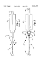
- FIG. 1 illustrating, typically, a laser 5 having a laser cavity 7 extending between mirrors 9 and 11 with lens 13 positioned in the laser cavity between mirror 9 and Brewster window 15 of a laser medium 17 (shown in FIG. 1 as a gas laser medium within the laser cavity).
- mirror surfaces show lower apparent degradation rates than anti-reflection coated surfaces of transmissive optics, even when in similar environments. This observation is consistent with the contamination that consists of substantially non-absorbing (or dielectric) Material that condenses to form relatively uniform films oil intracavity surfaces.
- a dielectric film deposited on a mirror surface will typically degrade its nominally high reflectance only a small amount, while a dielectric film deposited on an anti-reflection coated surface, or on a Brewster surface, normally raises its nominally low reflectance, and at least in some cases, does so quite dramaticaly.
- This invention provides apparatus and method for minimizing power degradation in a laser device, and, particularly, in a laser device having a laser cavity operating in a predetermined spatial mode having predetermined light beam wavefronts within the laser cavity mode.
- An optically transmissive unit placed within the laser cavity has at least one intracavity optical surface that may be positioned at or provides one end of a laser medium that is within the laser cavity with the intracavity optical surface being substantially coincident with the light beam, or laser mode, wavefronts within the laser cavity to minimize power losses in the laser cavity due to contamination buildup at the intracavity optical surface.
- the transmissive optic unit may also include a second optical surface positioned to be less exposed to contamination buildup, with the second optical unit having a configuration suitable for providing needed focal properties for the optic unit.
- One or more of the optical surfaces of the transmissive optic unit can, and normally has, a reflection coating thereon, such as an anti-reflection (i.e., highly transmissive) coating or a high reflection (i.e., substantially non-transmissive) coating.
- a reflection coating such as an anti-reflection (i.e., highly transmissive) coating or a high reflection (i.e., substantially non-transmissive) coating.
- Contamination buildup on the optical surface including on the reflection coating on the optical surface where utilized, causes a change in reflectance at the optical surface, with an increase in reflectance resulting in power losses in the laser cavity.
- the effect of increased reflectance is minimized by the curvature and/or orientation of the intracavity optical surface such that light reflected from the intracavity optical surface is maintained within the laser cavity as occurs when the surface is substantially coincident with the light beam wavefronts.
- FIG. 1 is a simplified side view showing a typical prior art laser device having an optic unit within the laser cavity;
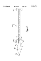
- FIG. 2 is a side view illustrating apparatus according to this invention wherein the optically transmissive unit is an optic unit that includes an intracavity optical surface positioned at one end of a gas laser medium; and
- FIG. 3 is a side view illustrating apparatus according to this invention wherein the optically transmissive unit includes optical surfaces that provide opposite ends of a solid state laser medium.
- optically transmissive unit 20 of laser 22 may be positioned within laser cavity 24, as is shown in FIG. 2, to minimize performance degradation of laser 22.
- laser 22 includes mirrors 26 and 28 and a gas laser medium 30 within laser cavity 24.
- optically transmissive unit 20 is an optic unit preferably positioned at one end of gas laser medium 30 with the optic unit being preferably mounted at the end of the laser medium using mount 32 shaped such that there is an annular indention 34 between the body of the laser medium and mount 32 so that mount 32 can be angularly moved, or displaced, relative to the body of laser medium 30 in order to align, or orient, the optic unit.
- Displacement of mount 32 relative to the body of laser medium 30 can be accomplished, for example, by forcing mount 32 away from the body of laser medium 30 at a selected point along indention 34. This is commonly accomplished by a screwdriver, or the like, inserted in annular indention 34 to wedge the mount away from the body of the laser medium and thereby provide a slight angular displacement of the mount relative to the body of the laser medium to thereby align, or orient, the optic unit.
- Optic unit 20 includes an intracavity optical surface 36 positioned, as shown in FIG. 2, to be subject to contamination buildup, with surface 36 having a specific curvature and orientation for effecting performance degradation minimization, and, particularly, for minimizing the effect of increased reflectance on the surface (surface 36 may, but not necessarily, have thereon an anti-reflection coating 38, i.e., a coating that is highly transmissive, up to ninety percent or better, at the wavelength utilized).
- an anti-reflection coating 38 i.e., a coating that is highly transmissive, up to ninety percent or better, at the wavelength utilized.
- curvature and orientation of the surface are chosen so that the surface is substantially coincident with the wavefronts 42 of the cavity mode at the location of the surface, as indicated in FIG. 2, with best results again occurring when the surface is precisely coincident with the light beam wavefronts.
- the wavefronts of the cavity mode will, of course, have more or less curvature dependent upon the geometrical configurations of the cavity utilized, and, obviously, the optical surface will need to have substantially the same curvature to achieve acceptable coincidence.
- optic unit 20 can include a second optical surface 44, and this surface may also (but not necessarily) have a reflection coating thereon like that of coating 38 on surface 36.
- Surface 44 is preferably positioned to be less susceptible to contamination buildup than is intracavity optical surface 36, and hence can be utilized to provide needed focal properties for the optic unit.
- transmissive optic unit By positioning the transmissive optic unit within the laser cavity with one surface in a position relatively more susceptible to contamination buildup (i.e., intracavity optical surface 36, as indicated in FIG. 2) to thus expose this surface to the significant contamination sources, and positioning the other surface (i.e., second optical surface 44, as indicated in FIG. 2)) so that this surface is less exposed to significant contamination sources, significant minimizing of performance degradation is achieved while allowing the optic unit to still fulfill its intended function of providing the necessary focal properties as needed.
- contamination buildup i.e., intracavity optical surface 36, as indicated in FIG. 2
- intracavity optical surface 36 chosen to be coincident with the cavity mode wavefronts to thereby minimize the performance degradation associated with the contamination, has a concave curvature, as shown in FIG. 2, while second optical surface 44, chosen to give the optic unit the desired overall focal properties to permit the optic unit to perform its intended function, may have, by way of example, a convex curvature, as shown in FIG. 2.
- mount 32 be slightly displaceable with respect to laser cavity 24 to provide fine adjustment, to control the orientation of the optic unit, and, particularly, the intracavity optical surface of the optic unit.
- performance degradation minimization may also be realized in conjunction with a solid state laser medium in the laser cavity in lieu of a gas laser medium as shown in FIG. 2.
- solid state laser medium 48 such as, for example a Nd:YAG crystal
- pump bear 52 from a pump source 54 (such as a semiconductor laser) through lens 56, as is now well known for pumping solid state lasers.
- Solid state laser medium 48 has a high reflection coating 58 (i.e., high reflectance (approaching total reflectance) at the utilized transverse mode of the laser cavity but highly transmissive (ninety percent or better) at the pump wavelength) on end, or side, 60 of the solid state laser medium receiving the pump beam from the pump source, solid state laser medium 48 also has an anti-reflection coating 62 (i.e., highly transmissive at the utilized wavelength of the laser cavity) on end, or side, 64 opposite to that of end 60 with laser cavity 50 being formed between end 60 (with coating 58 thereon) and mirror 66 (positioned outwardly from end 64).
- a high reflection coating 58 i.e., high reflectance (approaching total reflectance) at the utilized transverse mode of the laser cavity but highly transmissive (ninety percent or better) at the pump wavelength
- solid state laser medium 48 also has an anti-reflection coating 62 (i.e., highly transmissive at the utilized wavelength of the laser cavity) on end, or side,
- coated ends 60 and 64 of solid state laser medium 48 are substantially coincident with substantially planar wavefronts 68 of the cavity mode, as is indicated in FIG. 3, to thus minimize performance degradation in the laser device in the same manner as brought out above with respect to the curved surfaces of the intracavity optical surface illustrated in FIG. 2.
- best results occur when the surfaces are precisely coincident with the wavefronts of the cavity mode.
- this invention provides apparatus and method for minimizing the effect of contamination buildup on intracavity optical surfaces to thereby minimize performance degradation in a laser device.
Landscapes
- Physics & Mathematics (AREA)
- Electromagnetism (AREA)
- Engineering & Computer Science (AREA)
- Plasma & Fusion (AREA)
- Optics & Photonics (AREA)
- Lasers (AREA)
Abstract
Description
Claims (27)
Priority Applications (1)
| Application Number | Priority Date | Filing Date | Title |
|---|---|---|---|
| US08/895,965 US5907575A (en) | 1997-07-17 | 1997-07-17 | Apparatus and method for minimizing performance degradation in a laser device |
Applications Claiming Priority (1)
| Application Number | Priority Date | Filing Date | Title |
|---|---|---|---|
| US08/895,965 US5907575A (en) | 1997-07-17 | 1997-07-17 | Apparatus and method for minimizing performance degradation in a laser device |
Publications (1)
| Publication Number | Publication Date |
|---|---|
| US5907575A true US5907575A (en) | 1999-05-25 |
Family
ID=25405375
Family Applications (1)
| Application Number | Title | Priority Date | Filing Date |
|---|---|---|---|
| US08/895,965 Expired - Lifetime US5907575A (en) | 1997-07-17 | 1997-07-17 | Apparatus and method for minimizing performance degradation in a laser device |
Country Status (1)
| Country | Link |
|---|---|
| US (1) | US5907575A (en) |
Citations (2)
| Publication number | Priority date | Publication date | Assignee | Title |
|---|---|---|---|---|
| US3696310A (en) * | 1970-10-01 | 1972-10-03 | Bell Telephone Labor Inc | Mode-locking in semiconductor lasers |
| US5012483A (en) * | 1990-09-27 | 1991-04-30 | The United States Of America As Represented By The Secretary Of The Navy | Narrow-bandwidth diffraction-limited coupled stable-unstable resonator laser cavity |
-
1997
- 1997-07-17 US US08/895,965 patent/US5907575A/en not_active Expired - Lifetime
Patent Citations (2)
| Publication number | Priority date | Publication date | Assignee | Title |
|---|---|---|---|---|
| US3696310A (en) * | 1970-10-01 | 1972-10-03 | Bell Telephone Labor Inc | Mode-locking in semiconductor lasers |
| US5012483A (en) * | 1990-09-27 | 1991-04-30 | The United States Of America As Represented By The Secretary Of The Navy | Narrow-bandwidth diffraction-limited coupled stable-unstable resonator laser cavity |
Similar Documents
| Publication | Publication Date | Title |
|---|---|---|
| US6301274B1 (en) | Tunable external cavity laser | |
| US6314117B1 (en) | Laser diode package | |
| EP0742965B1 (en) | Thermal lens of controlled ellipticity | |
| EP0469067A1 (en) | External cavity semiconductor laser | |
| JP2005513791A (en) | Retroreflective devices especially for tunable lasers | |
| US20080166085A1 (en) | Semiconductor laser module | |
| CN112352172A (en) | Apparatus and method for coupling laser light to photonic integrated circuit | |
| KR970005169B1 (en) | Self aligning internal cavity Raman laser | |
| US4818053A (en) | Optical bench for a semiconductor laser and method | |
| US4762386A (en) | Optical fiber assembly including means utilizing a column load to compensate for thermal effects | |
| EP1074075A1 (en) | Fiber grating feedback stabilization of broad area laser diode | |
| US11256039B2 (en) | Methods and systems for laser cleaving optical fibers | |
| US5392372A (en) | Optical coupling equipment for an optical semiconductor and an optical fiber | |
| JP2004138996A (en) | Fabry-Perot apparatus for compensating half-width energy error and method of manufacturing the same | |
| WO1997023932A1 (en) | Multi-element monolithic solid state laser | |
| US9077137B2 (en) | Laser assembly with package beam pointing registration | |
| US5907575A (en) | Apparatus and method for minimizing performance degradation in a laser device | |
| JPH04245686A (en) | Laser, and method of optimizing laser mode performance | |
| US5299220A (en) | Slab laser | |
| US5235610A (en) | Prism gain module and method | |
| EP3637171B1 (en) | Apparatus for projecting a light spot | |
| US4831632A (en) | Method and apparatus for optically aligning a laser cavity | |
| KR20110126720A (en) | Optical contact system with lens with axial astigmatism | |
| US20070104231A1 (en) | Wavelength tunable resonator with a prism | |
| CN213544924U (en) | Reflecting mirror assembly |
Legal Events
| Date | Code | Title | Description |
|---|---|---|---|
| AS | Assignment |
Owner name: RESEARCH ELECTRO-OPTICS, INC., COLORADO Free format text: ASSIGNMENT OF ASSIGNORS INTEREST;ASSIGNOR:SANDBERG, JON C.;REEL/FRAME:008726/0244 Effective date: 19970717 |
|
| STCF | Information on status: patent grant |
Free format text: PATENTED CASE |
|
| FEPP | Fee payment procedure |
Free format text: PAYOR NUMBER ASSIGNED (ORIGINAL EVENT CODE: ASPN); ENTITY STATUS OF PATENT OWNER: SMALL ENTITY |
|
| FPAY | Fee payment |
Year of fee payment: 4 |
|
| REMI | Maintenance fee reminder mailed | ||
| FPAY | Fee payment |
Year of fee payment: 8 |
|
| FEPP | Fee payment procedure |
Free format text: PAYER NUMBER DE-ASSIGNED (ORIGINAL EVENT CODE: RMPN); ENTITY STATUS OF PATENT OWNER: SMALL ENTITY Free format text: PAYOR NUMBER ASSIGNED (ORIGINAL EVENT CODE: ASPN); ENTITY STATUS OF PATENT OWNER: SMALL ENTITY |
|
| FPAY | Fee payment |
Year of fee payment: 12 |
|
| AS | Assignment |
Owner name: PNC BANK, NATIONAL ASSOCIATION, PENNSYLVANIA Free format text: SECURITY AGREEMENT;ASSIGNORS:TSI INCORPORATED;ENVIRONMENTAL SYSTEMS CORPORATION;DICKEY-JOHN CORPORATION;REEL/FRAME:029169/0775 Effective date: 20120620 |