US5902071A - Plastic permeable groyne system - Google Patents
Plastic permeable groyne system Download PDFInfo
- Publication number
- US5902071A US5902071A US08/893,112 US89311297A US5902071A US 5902071 A US5902071 A US 5902071A US 89311297 A US89311297 A US 89311297A US 5902071 A US5902071 A US 5902071A
- Authority
- US
- United States
- Prior art keywords
- concrete
- pipes
- groyne
- assembly
- apertures
- Prior art date
- Legal status (The legal status is an assumption and is not a legal conclusion. Google has not performed a legal analysis and makes no representation as to the accuracy of the status listed.)
- Expired - Fee Related
Links
- 230000009471 action Effects 0.000 description 5
- 239000004576 sand Substances 0.000 description 5
- 230000003628 erosive effect Effects 0.000 description 3
- XLYOFNOQVPJJNP-UHFFFAOYSA-N water Substances O XLYOFNOQVPJJNP-UHFFFAOYSA-N 0.000 description 3
- 230000015572 biosynthetic process Effects 0.000 description 2
- 239000000463 material Substances 0.000 description 2
- 238000000034 method Methods 0.000 description 2
- 230000002265 prevention Effects 0.000 description 2
- 230000001681 protective effect Effects 0.000 description 2
- 230000009467 reduction Effects 0.000 description 2
- 238000007796 conventional method Methods 0.000 description 1
- 238000000151 deposition Methods 0.000 description 1
- 230000001066 destructive effect Effects 0.000 description 1
- 230000000694 effects Effects 0.000 description 1
- 238000012986 modification Methods 0.000 description 1
- 230000004048 modification Effects 0.000 description 1
- 230000008569 process Effects 0.000 description 1
- 230000003014 reinforcing effect Effects 0.000 description 1
- 238000004162 soil erosion Methods 0.000 description 1
- 239000000126 substance Substances 0.000 description 1
- 230000007704 transition Effects 0.000 description 1
Images
Classifications
-
- E—FIXED CONSTRUCTIONS
- E02—HYDRAULIC ENGINEERING; FOUNDATIONS; SOIL SHIFTING
- E02B—HYDRAULIC ENGINEERING
- E02B3/00—Engineering works in connection with control or use of streams, rivers, coasts, or other marine sites; Sealings or joints for engineering works in general
- E02B3/04—Structures or apparatus for, or methods of, protecting banks, coasts, or harbours
- E02B3/06—Moles; Piers; Quays; Quay walls; Groynes; Breakwaters ; Wave dissipating walls; Quay equipment
-
- Y—GENERAL TAGGING OF NEW TECHNOLOGICAL DEVELOPMENTS; GENERAL TAGGING OF CROSS-SECTIONAL TECHNOLOGIES SPANNING OVER SEVERAL SECTIONS OF THE IPC; TECHNICAL SUBJECTS COVERED BY FORMER USPC CROSS-REFERENCE ART COLLECTIONS [XRACs] AND DIGESTS
- Y02—TECHNOLOGIES OR APPLICATIONS FOR MITIGATION OR ADAPTATION AGAINST CLIMATE CHANGE
- Y02A—TECHNOLOGIES FOR ADAPTATION TO CLIMATE CHANGE
- Y02A10/00—TECHNOLOGIES FOR ADAPTATION TO CLIMATE CHANGE at coastal zones; at river basins
- Y02A10/11—Hard structures, e.g. dams, dykes or breakwaters
Definitions
- This invention relates, in general, to permeable groynes, and, in particular, to permeable groynes which absorb wave energy and deposit sand uniformly on both sides of the groyne.
- U.S. Pat. No. 3,344,609 discloses a layer of thin, flexible foraminius sheet material which is pervious to water but not pervious to the substance of the littoral formation. The material is laid onto the littoral formation and has means for preventing the entrance of water beneath edge portions of the layer.
- U.S. Pat. No. 4,417,842 discloses an apparatus for aligning and loading inserts for soil erosion prevention blocks.
- the apparatus has a rollable main frame with an insert holder. Secured within the insert holder is an aligning frame which receives the inserts and aligns them in a desired manner.
- U.S. Pat. No. 5,069,579 discloses an erosion prevention device comprising a concrete block which receives current reduction flaps on the top of the block.
- the reduction flaps reduce the wave action and, therefore, lessen their effect on the shore.
- U.S. Pat. No. 5,556,230 discloses a cylindrical armor unit for use in a revetment structure, the units interlock along all major axes with a flexible interlocking structure so that they can be placed along shorelines with abrupt transitions.
- the present invention comprises a system of plastic pipes which are anchored vertically in place along a shoreline by a concrete form that will position the pipes with a specific distance between pipes. Once the pipes are positioned, a concrete cap will be poured to permanently secure the pipes, after which the concrete form can be removed and moved to a new location.
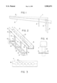
- FIG. 1 is a side view of the present invention when installed.
- FIG. 2 is a perspective view of a form used to assemble the present invention.
- FIG. 3 is a top view of the form used to assemble the present invention.
- FIG. 4 is an end view showing the concrete cap and one of the pipes of the present invention.
- FIG. 1 shows the present invention after it has been assembled on a shoreline.
- Hollow plastic pipes 2 have been mounted into the ground 3 which is subject to wind forces and wave action from water 4.
- Attached to the pipes 2 is a concrete cap 1 which has been formed using the concrete form shown in FIGS. 2-4.
- the number of pipes 2 shown are merely for illustrational purposes, and more or fewer pipes can be used depending on the severity of the wind and wave action that will be experienced in a particular area.
- the form shown in FIG. 2 has eight apertures 12 for receiving the pipes 2 and the apertures are positioned in a straight line. Depending on the circumstances, more or less than eight pipes can be formed by adjusting the dimensions of the form.
- the apertures do not have to be positioned in a straight line, but rather other positions such as, but not limited to, a double row of staggered apertures may be used.
- FIG. 2 The form used to form the groyne, shown in FIG. 1, is shown in FIG. 2.
- the form comprises a frame composed of vertical legs 9 which are connected by any conventional method to horizontal cross pieces 10.
- the frame is made in two parts which meet at a joint line 11 which will allow the frame to be easily separated once the concrete is poured and allowed to set properly.
- the two halves of the frame can be secured by any conventional means such as nuts and bolts, not shown.
- Attached to the top of the frame is a concrete form having a bottom 7 to which are attached sides 5 by hinges 6.
- the hinges allow the sides to be pivoted away from the concrete cap 1 after it has been poured and allowed to set. This will allow the form to be dissembled easier.
- the floor 7 can be made in halves which meet at a joint line 8 to help in the dissembly of the form.
- the form halves can be secured by any conventional concrete form clamp, not shown, while the concrete is being poured.
- a pipe holding assembly 13 which is similar to the form 7 except is does not have any sides.
- the assembly 13 will be used to help hold the pipes 2 while the concrete is being poured.
- the assembly 13 can also be made in halves similar to the frame and the top form.
- FIG. 2 In use, the form shown in FIG. 2 would be assembled in the desired location. Pipes 2 would be inserted into the apertures 12 in the floor 7 of the top form and into the apertures 12 in the pipe holding assembly 13. The pipes could be passed through the apertures after the frame and the concrete form is assembled, or they could be positioned before the halves of the frame are joined. As shown in FIG. 1, the length of the pipes 2 can be varied depending on the location where they will be installed. In addition, the apertures 12, as shown in FIG. 3 are prespaced so the pipes 2 will be separated from each other. This spacing will allow sand to accumulate between the pipes.
- the frames and form can be disassembled and moved to a new site, where the process will be repeated as many times as necessary.
Landscapes
- Engineering & Computer Science (AREA)
- General Engineering & Computer Science (AREA)
- Environmental & Geological Engineering (AREA)
- Ocean & Marine Engineering (AREA)
- Mechanical Engineering (AREA)
- Civil Engineering (AREA)
- Structural Engineering (AREA)
- Revetment (AREA)
Abstract
A system of plastic pipes which are anchored vertically in place along a shoreline by a concrete form that will position the pipes with a specific distance between pipes. Once the pipes are positioned, a concrete cap will be poured to permanently secure the pipes, after which the concrete form can be removed and moved to a new location.
Description
This invention relates, in general, to permeable groynes, and, in particular, to permeable groynes which absorb wave energy and deposit sand uniformly on both sides of the groyne.
In the prior art various types of protective groynes. For example, U.S. Pat. No. 3,344,609 discloses a layer of thin, flexible foraminius sheet material which is pervious to water but not pervious to the substance of the littoral formation. The material is laid onto the littoral formation and has means for preventing the entrance of water beneath edge portions of the layer.
U.S. Pat. No. 4,417,842 discloses an apparatus for aligning and loading inserts for soil erosion prevention blocks. The apparatus has a rollable main frame with an insert holder. Secured within the insert holder is an aligning frame which receives the inserts and aligns them in a desired manner.
U.S. Pat. No. 5,069,579 discloses an erosion prevention device comprising a concrete block which receives current reduction flaps on the top of the block. The reduction flaps reduce the wave action and, therefore, lessen their effect on the shore.
U.S. Pat. No. 5,556,230 discloses a cylindrical armor unit for use in a revetment structure, the units interlock along all major axes with a flexible interlocking structure so that they can be placed along shorelines with abrupt transitions.
While the prior art devices work in their intended manner, all of them are concerned with preventing the destructive action of wave energy upon the shore line. However, this is only one of the major problems associated with beach erosion. The other problem, which has not been recognized by the prior art is the depositing of sand uniformly on both side s of the protective system, which will not only protect the shore line, but also help to build up or reconstruct the shore line.
The present invention comprises a system of plastic pipes which are anchored vertically in place along a shoreline by a concrete form that will position the pipes with a specific distance between pipes. Once the pipes are positioned, a concrete cap will be poured to permanently secure the pipes, after which the concrete form can be removed and moved to a new location.
It is an object of the present invention to provide a new and improved groyne system to protect a shoreline from wave action.
It is an object of the present invention to provide a new and improved groyne system which will help to redistribute sand on both sides of the groyne system
These and other objects and advantages of the present invention will be fully apparent from the following description, when taken in connection with the annexed drawings.
FIG. 1 is a side view of the present invention when installed.
FIG. 2 is a perspective view of a form used to assemble the present invention.
FIG. 3 is a top view of the form used to assemble the present invention.
FIG. 4 is an end view showing the concrete cap and one of the pipes of the present invention.
Referring now to the drawings in greater detail, FIG. 1 shows the present invention after it has been assembled on a shoreline. Hollow plastic pipes 2 have been mounted into the ground 3 which is subject to wind forces and wave action from water 4. Attached to the pipes 2 is a concrete cap 1 which has been formed using the concrete form shown in FIGS. 2-4. Also, it should be noted that the number of pipes 2 shown are merely for illustrational purposes, and more or fewer pipes can be used depending on the severity of the wind and wave action that will be experienced in a particular area. For example the form shown in FIG. 2 has eight apertures 12 for receiving the pipes 2 and the apertures are positioned in a straight line. Depending on the circumstances, more or less than eight pipes can be formed by adjusting the dimensions of the form. In addition, the apertures do not have to be positioned in a straight line, but rather other positions such as, but not limited to, a double row of staggered apertures may be used.
The form used to form the groyne, shown in FIG. 1, is shown in FIG. 2. The form comprises a frame composed of vertical legs 9 which are connected by any conventional method to horizontal cross pieces 10. The frame is made in two parts which meet at a joint line 11 which will allow the frame to be easily separated once the concrete is poured and allowed to set properly. The two halves of the frame can be secured by any conventional means such as nuts and bolts, not shown.
Attached to the top of the frame is a concrete form having a bottom 7 to which are attached sides 5 by hinges 6. The hinges allow the sides to be pivoted away from the concrete cap 1 after it has been poured and allowed to set. This will allow the form to be dissembled easier. In addition the floor 7 can be made in halves which meet at a joint line 8 to help in the dissembly of the form. The form halves can be secured by any conventional concrete form clamp, not shown, while the concrete is being poured.
Mounted adjacent to the bottom of the frame is a pipe holding assembly 13 which is similar to the form 7 except is does not have any sides. The assembly 13 will be used to help hold the pipes 2 while the concrete is being poured. The assembly 13 can also be made in halves similar to the frame and the top form.
In use, the form shown in FIG. 2 would be assembled in the desired location. Pipes 2 would be inserted into the apertures 12 in the floor 7 of the top form and into the apertures 12 in the pipe holding assembly 13. The pipes could be passed through the apertures after the frame and the concrete form is assembled, or they could be positioned before the halves of the frame are joined. As shown in FIG. 1, the length of the pipes 2 can be varied depending on the location where they will be installed. In addition, the apertures 12, as shown in FIG. 3 are prespaced so the pipes 2 will be separated from each other. This spacing will allow sand to accumulate between the pipes.
When the form and all the pipes are in position, concrete will be poured into the form 5, 7 and the concrete will flow into the interior of the pipes 2 to form a stable structure which will be able to withstand the forces of wind and wave action and will protect the shore from erosion. In addition, the pilings or pipes 2 will give the sand a place to accumulate.
Also, it should be noted that while not shown in the drawings, conventional reinforcing bars can be added to the pipes 2 and between the sides 5 to reinforce the concrete.
After the concrete has been allowed to set, the frames and form can be disassembled and moved to a new site, where the process will be repeated as many times as necessary.
Although the Plastic Permeable Groyne System and the method of using the same according to the present invention has been described in the foregoing specification with considerable details, it is to be understood that modifications may be made to the invention which do not exceed the scope of the appended claims and modified forms of the present invention done by others skilled in the art to which the invention pertains will be considered infringements of this invention when those modified forms fall within the claimed scope of this invention.
Claims (6)
1. An assembly for making a concrete groyne comprising:
a frame having vertical members and horizontal members,
said frame being formed in two halves which are secured together,
a concrete form attached to an upper portion of said frame,
said concrete form having a floor and at least two vertical sides,
said floor having apertures formed therein, and
a pipe holding assembly secured to a lower portion of said frame,
said pipe holding assembly having apertures formed therein,
said apertures in said pipe holding assembly and said apertures in said floor being vertically aligned, wherein pipes are positioned in said apertures in said floor and in said apertures in said pipe holding assembly.
2. The assembly for making a concrete groyne as claimed in claim 1, wherein said floor is made in two halves.
3. The assembly for making a concrete groyne as claimed in claim 1, wherein said pipe holding assembly is made in two halves.
4. The assembly for making a concrete groyne as claimed in claim 1, wherein said sides are hinged to said floor.
5. The assembly for making a concrete groyne as claimed in claim 1, wherein concrete is placed between said sides and said floor, and said concrete is also placed inside said pipes.
6. A concrete groyne made by the assembly as claimed in claim 1.
Priority Applications (1)
| Application Number | Priority Date | Filing Date | Title |
|---|---|---|---|
| US08/893,112 US5902071A (en) | 1997-07-15 | 1997-07-15 | Plastic permeable groyne system |
Applications Claiming Priority (1)
| Application Number | Priority Date | Filing Date | Title |
|---|---|---|---|
| US08/893,112 US5902071A (en) | 1997-07-15 | 1997-07-15 | Plastic permeable groyne system |
Publications (1)
| Publication Number | Publication Date |
|---|---|
| US5902071A true US5902071A (en) | 1999-05-11 |
Family
ID=25401052
Family Applications (1)
| Application Number | Title | Priority Date | Filing Date |
|---|---|---|---|
| US08/893,112 Expired - Fee Related US5902071A (en) | 1997-07-15 | 1997-07-15 | Plastic permeable groyne system |
Country Status (1)
| Country | Link |
|---|---|
| US (1) | US5902071A (en) |
Citations (11)
| Publication number | Priority date | Publication date | Assignee | Title |
|---|---|---|---|---|
| US247065A (en) * | 1881-09-13 | Hekry f | ||
| US867802A (en) * | 1907-01-29 | 1907-10-08 | William C Cottrell | Reinforced concrete jetty. |
| US1812300A (en) * | 1929-06-12 | 1931-06-30 | Charles T Leeds | Concrete block groin or sea wall |
| US2750790A (en) * | 1953-01-16 | 1956-06-19 | Henry M Peper | Masonry block mortar strip gauging device |
| US3280569A (en) * | 1964-02-11 | 1966-10-25 | Permagroin Company Inc | Groin |
| US3344609A (en) * | 1959-10-23 | 1967-10-03 | Carthage Mills Inc | Prevention of beach erosion and encouragement of land restoration |
| US3779021A (en) * | 1971-12-27 | 1973-12-18 | R Green | Method of making a headwall |
| US4417842A (en) * | 1980-11-04 | 1983-11-29 | Landry Jr Kossuth J | Soil erosion prevention block insert and apparatus for positioning |
| US5069579A (en) * | 1990-03-14 | 1991-12-03 | Richard Burns | Erosion prevention device |
| US5551662A (en) * | 1995-10-17 | 1996-09-03 | Keady; Paul A. | Stone post guide system |
| US5556230A (en) * | 1994-10-19 | 1996-09-17 | U.S. Army Corps Of Engineers As Represented By The Secretary Of The Army | Concrete armor unit for the protection of coastal, shore lines and hydraulic structures |
-
1997
- 1997-07-15 US US08/893,112 patent/US5902071A/en not_active Expired - Fee Related
Patent Citations (11)
| Publication number | Priority date | Publication date | Assignee | Title |
|---|---|---|---|---|
| US247065A (en) * | 1881-09-13 | Hekry f | ||
| US867802A (en) * | 1907-01-29 | 1907-10-08 | William C Cottrell | Reinforced concrete jetty. |
| US1812300A (en) * | 1929-06-12 | 1931-06-30 | Charles T Leeds | Concrete block groin or sea wall |
| US2750790A (en) * | 1953-01-16 | 1956-06-19 | Henry M Peper | Masonry block mortar strip gauging device |
| US3344609A (en) * | 1959-10-23 | 1967-10-03 | Carthage Mills Inc | Prevention of beach erosion and encouragement of land restoration |
| US3280569A (en) * | 1964-02-11 | 1966-10-25 | Permagroin Company Inc | Groin |
| US3779021A (en) * | 1971-12-27 | 1973-12-18 | R Green | Method of making a headwall |
| US4417842A (en) * | 1980-11-04 | 1983-11-29 | Landry Jr Kossuth J | Soil erosion prevention block insert and apparatus for positioning |
| US5069579A (en) * | 1990-03-14 | 1991-12-03 | Richard Burns | Erosion prevention device |
| US5556230A (en) * | 1994-10-19 | 1996-09-17 | U.S. Army Corps Of Engineers As Represented By The Secretary Of The Army | Concrete armor unit for the protection of coastal, shore lines and hydraulic structures |
| US5551662A (en) * | 1995-10-17 | 1996-09-03 | Keady; Paul A. | Stone post guide system |
Similar Documents
| Publication | Publication Date | Title |
|---|---|---|
| US6558075B2 (en) | Permanent and semi-permanent groyne structures and method for shoreline and land mass reclamation | |
| RU2196864C2 (en) | Cellular retention structure | |
| US4372705A (en) | Articulated erosion control system | |
| CA2713304C (en) | Erosion control ballast and soil confinement mat | |
| US5178489A (en) | Hydrodynamic control system | |
| US6893193B2 (en) | Self-anchoring fiber block system | |
| USRE32663E (en) | Articulated erosion control system | |
| US5622448A (en) | Panel ditch check for temporary erosion and sediment control | |
| CN114703770B (en) | Box culvert construction process | |
| CA2586546C (en) | Culvert bundle for stream crossings and flow-through bridge abutments | |
| US4998847A (en) | Drainage conduit which is resistant to clogging by beavers | |
| US2655790A (en) | Means to deposit water-borne sand | |
| US11661716B1 (en) | Erosion control system for preventing shoreline erosion | |
| CA2489210C (en) | Revetment useful to line stream bed and assembly of said revetments | |
| US20180187387A1 (en) | Modular wave-break and bulkhead system | |
| US6688810B2 (en) | Revetment useful to line stream bed and assembly of said revetments | |
| US5902071A (en) | Plastic permeable groyne system | |
| JPH04108916A (en) | Construction method for reinforced banking body | |
| US20030223824A1 (en) | Wall system | |
| JPH11350505A (en) | Stone retaining wall | |
| CN217679151U (en) | Adjustable slope protection pile for foundation pit | |
| JP2003278130A (en) | Seawall structure and seawall construction method | |
| EP2946040B1 (en) | Canal-sealing means | |
| JPH04108915A (en) | Construction method for reinforced banking body | |
| RU2044823C1 (en) | Partitioning structure and method for assembly the same |
Legal Events
| Date | Code | Title | Description |
|---|---|---|---|
| FPAY | Fee payment |
Year of fee payment: 4 |
|
| FPAY | Fee payment |
Year of fee payment: 8 |
|
| REMI | Maintenance fee reminder mailed | ||
| LAPS | Lapse for failure to pay maintenance fees | ||
| STCH | Information on status: patent discontinuation |
Free format text: PATENT EXPIRED DUE TO NONPAYMENT OF MAINTENANCE FEES UNDER 37 CFR 1.362 |
|
| FP | Lapsed due to failure to pay maintenance fee |
Effective date: 20110511 |