US5894502A - High-frequency voltage generator for an X-ray tube - Google Patents
High-frequency voltage generator for an X-ray tube Download PDFInfo
- Publication number
- US5894502A US5894502A US08/874,149 US87414997A US5894502A US 5894502 A US5894502 A US 5894502A US 87414997 A US87414997 A US 87414997A US 5894502 A US5894502 A US 5894502A
- Authority
- US
- United States
- Prior art keywords
- inverter
- voltage
- ray tube
- cathode
- anode
- Prior art date
- Legal status (The legal status is an assumption and is not a legal conclusion. Google has not performed a legal analysis and makes no representation as to the accuracy of the status listed.)
- Expired - Fee Related
Links
- 230000003993 interaction Effects 0.000 claims 1
- 230000001105 regulatory effect Effects 0.000 abstract description 3
- 230000001276 controlling effect Effects 0.000 abstract description 2
- 230000000694 effects Effects 0.000 abstract 1
- 230000001419 dependent effect Effects 0.000 description 2
- 230000004048 modification Effects 0.000 description 2
- 238000012986 modification Methods 0.000 description 2
- 238000010586 diagram Methods 0.000 description 1
- 238000010438 heat treatment Methods 0.000 description 1
- 239000002184 metal Substances 0.000 description 1
- 239000004065 semiconductor Substances 0.000 description 1
Images
Classifications
-
- H—ELECTRICITY
- H05—ELECTRIC TECHNIQUES NOT OTHERWISE PROVIDED FOR
- H05G—X-RAY TECHNIQUE
- H05G1/00—X-ray apparatus involving X-ray tubes; Circuits therefor
- H05G1/08—Electrical details
- H05G1/10—Power supply arrangements for feeding the X-ray tube
-
- H—ELECTRICITY
- H05—ELECTRIC TECHNIQUES NOT OTHERWISE PROVIDED FOR
- H05G—X-RAY TECHNIQUE
- H05G1/00—X-ray apparatus involving X-ray tubes; Circuits therefor
- H05G1/08—Electrical details
- H05G1/10—Power supply arrangements for feeding the X-ray tube
- H05G1/20—Power supply arrangements for feeding the X-ray tube with high-frequency AC; with pulse trains
-
- H—ELECTRICITY
- H05—ELECTRIC TECHNIQUES NOT OTHERWISE PROVIDED FOR
- H05G—X-RAY TECHNIQUE
- H05G1/00—X-ray apparatus involving X-ray tubes; Circuits therefor
- H05G1/08—Electrical details
- H05G1/26—Measuring, controlling or protecting
- H05G1/30—Controlling
- H05G1/32—Supply voltage of the X-ray apparatus or tube
Definitions
- the present invention is directed to a high-frequency voltage generator for supplying an X-ray tube, the X-ray tube being of the type having a metallic, centrally disposed part.
- a high-frequency voltage generator for an X-ray tube that supplies an X-ray tube of the type having metallic, or centrally disposed part.
- the cathode current is thereby unequal to the anode current since a part of the current flows off via the grounded metal middle part. Since the positive side of the high-voltage supply then is less loaded than the negative side, an asymmetrical voltage division with a higher anode voltage occurs. Due to the asymmetrical voltage division, thus, a shift of the center point of the high-voltage occurs.
- An object of the present invention is to provide a high-frequency generator for supplying an X-ray tube having a metallic middle part wherein a shift of the center point of the high-voltage is avoided.
- a high-frequency voltage generator for supplying an X-ray tube having a metallic middle part, the generator having a first high voltage rectifier with a (preceding inverter inverse rectifier) connected across the x-ray tube for supplying the overall voltage to the X-ray tube, and a second high voltage rectifier with another preceding inverter connected across the metallic middle part and the cathode, the first and second high voltage rectifiers and respectively following inverters being separately controlled by a control circuit.
- an rectifier is provided for the overall voltage across the X-ray tube and another inverse inverter is provided for the cathode voltage.
- These voltages are regulated independently of one another by controlling the frequency of each inverse rectifier.
- the ripples of these voltages therefore have different frequencies, but this is not disturbing since the influence of the cathode voltage ripple on the cathode or on the anode current is slight.
- the metallic middle part acts like the grating of an amplifier with little steepness.
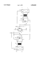
- the single FIGURE is a circuit diagram of a high voltage generator for supplying an X-ray tube, constructed and operating in accordance with the principles of the present invention.
- the drawing shows an X-ray tube 1 with metallic middle part 2.
- the overall voltage across the X-ray tube 1 is supplied by a high-voltage rectifier 3.
- the high-voltage rectifier 3 is connected to a inverter 6 via a high-voltage transformer 4.
- the inverter 6 is supplied from the mains via a rectifier in a known way.
- the inverter 11 is also supplied from the mains via a rectifier in a known way.
- the overall voltage at the X-ray tube 1 is controlled as a manipulated variable dependent on the frequency of the inverter 6.
- the actual value is taken at a potentiometer 12.
- the cathode voltage is regulated as a manipulated variable dependent on the frequency of the inverter 11.
- the actual value is taken at a potentiometer 13.
- the illustrated generator is particularly suited for X-ray tubes having a highly pronounced asymmetry.
- the two inverters 6 and 11 can be identically structured and equipped with the same power semiconductors, thereby making of the high voltage generator easier to facilitate realization.
- a further advantage is that a certain voltage asymmetry can be intentionally set, thereby reducing the anode dissipated power, and thus also reducing heating of the anode.
Landscapes
- Health & Medical Sciences (AREA)
- General Health & Medical Sciences (AREA)
- Toxicology (AREA)
- X-Ray Techniques (AREA)
Abstract
In a high-voltage generator with an X-ray tube having a metallic middle part, unfavorable effects due to a part of the current flowing off via the grounded metallic middle part is avoided by the overall voltage across the X-ray tube being produced by one inverter and the cathode voltage of the X-ray tube is generated by another inverter, each having a high-voltage rectifier connected thereto. The respective voltages are regulated by controlling the respective inverters.
Description
1. Field of the Invention
The present invention is directed to a high-frequency voltage generator for supplying an X-ray tube, the X-ray tube being of the type having a metallic, centrally disposed part.
2. Description of the Prior Art
A high-frequency voltage generator for an X-ray tube is known that supplies an X-ray tube of the type having metallic, or centrally disposed part. The cathode current is thereby unequal to the anode current since a part of the current flows off via the grounded metal middle part. Since the positive side of the high-voltage supply then is less loaded than the negative side, an asymmetrical voltage division with a higher anode voltage occurs. Due to the asymmetrical voltage division, thus, a shift of the center point of the high-voltage occurs.
An object of the present invention is to provide a high-frequency generator for supplying an X-ray tube having a metallic middle part wherein a shift of the center point of the high-voltage is avoided.
The above object is achieved in accordance with the principles of the present invention in a high-frequency voltage generator for supplying an X-ray tube having a metallic middle part, the generator having a first high voltage rectifier with a (preceding inverter inverse rectifier) connected across the x-ray tube for supplying the overall voltage to the X-ray tube, and a second high voltage rectifier with another preceding inverter connected across the metallic middle part and the cathode, the first and second high voltage rectifiers and respectively following inverters being separately controlled by a control circuit.
In the inventive high-frequency high-voltage generator, an rectifier is provided for the overall voltage across the X-ray tube and another inverse inverter is provided for the cathode voltage. These voltages are regulated independently of one another by controlling the frequency of each inverse rectifier. The ripples of these voltages therefore have different frequencies, but this is not disturbing since the influence of the cathode voltage ripple on the cathode or on the anode current is slight. The metallic middle part acts like the grating of an amplifier with little steepness.
The single FIGURE is a circuit diagram of a high voltage generator for supplying an X-ray tube, constructed and operating in accordance with the principles of the present invention.
The drawing shows an X-ray tube 1 with metallic middle part 2. The overall voltage across the X-ray tube 1 is supplied by a high-voltage rectifier 3. The high-voltage rectifier 3 is connected to a inverter 6 via a high-voltage transformer 4. The inverter 6 is supplied from the mains via a rectifier in a known way.
The cathode voltage of the X-ray tube 1, i.e. the voltage between the metallic middle part 2 and the cathode 7, is supplied by a high-voltage rectifier 8 that is connected to a inverter 11 via a high-voltage transformer 9. The inverter 11 is also supplied from the mains via a rectifier in a known way.
The overall voltage at the X-ray tube 1 is controlled as a manipulated variable dependent on the frequency of the inverter 6. The actual value is taken at a potentiometer 12. The cathode voltage is regulated as a manipulated variable dependent on the frequency of the inverter 11. The actual value is taken at a potentiometer 13.
The illustrated generator is particularly suited for X-ray tubes having a highly pronounced asymmetry. Both inverters 6 and 11 are loaded about the same in the asymmetry range IA =0.35*IK which is generally the range of interest. IA is thereby the anode current, IK the cathode current. As a result, the two inverters 6 and 11 can be identically structured and equipped with the same power semiconductors, thereby making of the high voltage generator easier to facilitate realization.
A further advantage is that a certain voltage asymmetry can be intentionally set, thereby reducing the anode dissipated power, and thus also reducing heating of the anode.
Although modifications and changes may be suggested by those skilled in the art, it is the intention of the inventors to embody within the patent warranted hereon all changes and modifications as reasonably and properly come within the scope of their contribution to the art.
Claims (2)
1. An x-ray radiator comprising:
an x-ray tube having a housing containing an anode and a cathode between which electrons flow, and a metallic part disposed in said housing between said anode and said cathode at a location so that said metallic part has substantially no interaction with said electrons;
a first inverter connectible to a mains supply and having an output;
a first high voltage rectifier connected across said output of said first inverter and connected across said cathode and said anode of said x-ray tube for supplying an overall voltage to said x-ray tube;
a second inverter connectible to a mains supply, and having an output;
a second high voltage rectifier connected across said output of said second inverter and connected between said metallic part and said cathode for supplying a cathode voltage to said cathode; and
control means connected to said first inverter and to said second inverter for individually controlling said overall voltage and said cathode voltage.
2. An x-ray radiator as claimed in claim 1 wherein said first inverter operates at a first inverter operating frequency and wherein said second inverter operates at a second inverter operating frequency, and wherein said control means comprises means for controlling each of said first inverter operating frequency and said second inverter operating frequency for individually controlling said overall voltage and said cathode voltage.
Applications Claiming Priority (2)
| Application Number | Priority Date | Filing Date | Title |
|---|---|---|---|
| DE19631143A DE19631143C2 (en) | 1996-08-01 | 1996-08-01 | High-frequency X-ray generator |
| DE19631143 | 1996-08-01 |
Publications (1)
| Publication Number | Publication Date |
|---|---|
| US5894502A true US5894502A (en) | 1999-04-13 |
Family
ID=7801532
Family Applications (1)
| Application Number | Title | Priority Date | Filing Date |
|---|---|---|---|
| US08/874,149 Expired - Fee Related US5894502A (en) | 1996-08-01 | 1997-06-13 | High-frequency voltage generator for an X-ray tube |
Country Status (3)
| Country | Link |
|---|---|
| US (1) | US5894502A (en) |
| JP (1) | JPH1069998A (en) |
| DE (1) | DE19631143C2 (en) |
Cited By (2)
| Publication number | Priority date | Publication date | Assignee | Title |
|---|---|---|---|---|
| US20060023841A1 (en) * | 2003-01-09 | 2006-02-02 | Walter Beyerlein | High-voltage supply for an X-ray device |
| US10652989B2 (en) * | 2018-04-23 | 2020-05-12 | Siemens Healthcare Gmbh | Circuit arrangement |
Families Citing this family (1)
| Publication number | Priority date | Publication date | Assignee | Title |
|---|---|---|---|---|
| DE102009017649B4 (en) * | 2009-04-16 | 2015-04-09 | Siemens Aktiengesellschaft | Emission current control for X-ray tubes |
Citations (4)
| Publication number | Priority date | Publication date | Assignee | Title |
|---|---|---|---|---|
| GB2095007A (en) * | 1980-11-19 | 1982-09-22 | Philips Nv | X-ray generator including an X- ray tube provided with an intermediate electrode |
| US4439869A (en) * | 1981-09-04 | 1984-03-27 | U.S. Philips Corporation | X-Ray generator for an X-ray tube comprising a grounded grid |
| US5123038A (en) * | 1989-09-08 | 1992-06-16 | U.S. Philips Corporation | X-ray generator for operating an x-ray tube with parts of the tube connected to mass |
| US5155754A (en) * | 1990-11-27 | 1992-10-13 | Siemens Aktiengesellschaft | High frequency supply for an x-ray tube |
-
1996
- 1996-08-01 DE DE19631143A patent/DE19631143C2/en not_active Expired - Fee Related
-
1997
- 1997-06-13 US US08/874,149 patent/US5894502A/en not_active Expired - Fee Related
- 1997-07-30 JP JP9204404A patent/JPH1069998A/en not_active Withdrawn
Patent Citations (4)
| Publication number | Priority date | Publication date | Assignee | Title |
|---|---|---|---|---|
| GB2095007A (en) * | 1980-11-19 | 1982-09-22 | Philips Nv | X-ray generator including an X- ray tube provided with an intermediate electrode |
| US4439869A (en) * | 1981-09-04 | 1984-03-27 | U.S. Philips Corporation | X-Ray generator for an X-ray tube comprising a grounded grid |
| US5123038A (en) * | 1989-09-08 | 1992-06-16 | U.S. Philips Corporation | X-ray generator for operating an x-ray tube with parts of the tube connected to mass |
| US5155754A (en) * | 1990-11-27 | 1992-10-13 | Siemens Aktiengesellschaft | High frequency supply for an x-ray tube |
Cited By (3)
| Publication number | Priority date | Publication date | Assignee | Title |
|---|---|---|---|---|
| US20060023841A1 (en) * | 2003-01-09 | 2006-02-02 | Walter Beyerlein | High-voltage supply for an X-ray device |
| US7110499B2 (en) * | 2003-01-09 | 2006-09-19 | Siemens Aktiengesellschaft | High-voltage supply for an X-ray device |
| US10652989B2 (en) * | 2018-04-23 | 2020-05-12 | Siemens Healthcare Gmbh | Circuit arrangement |
Also Published As
| Publication number | Publication date |
|---|---|
| JPH1069998A (en) | 1998-03-10 |
| DE19631143C2 (en) | 2003-03-20 |
| DE19631143A1 (en) | 1998-02-05 |
Similar Documents
| Publication | Publication Date | Title |
|---|---|---|
| EP0253533B1 (en) | A circuit arrangement for producing high voltages | |
| EP0987818A2 (en) | Switching amplifier for generating continuous arbitrary waveforms for magnetic resonance imaging coils | |
| JPH08255694A (en) | X-ray device comprising power supply part for x-ray tube electric power supply | |
| US5894502A (en) | High-frequency voltage generator for an X-ray tube | |
| US4809310A (en) | Device for supplying current to a filament of an x-ray tube | |
| US5708694A (en) | X-ray generator | |
| US5469026A (en) | Method and apparatus for VF tube power supply | |
| US5914999A (en) | High-frequency voltage generator for supplying an X-ray tube | |
| US1654937A (en) | Regulation of electric distribution systems | |
| JPH08330079A (en) | Power source device for multi-electrode discharge | |
| US4794603A (en) | Power source for an axial-flow CO2 laser tube | |
| JP2856510B2 (en) | High voltage stabilized power supply | |
| US6229262B1 (en) | Electronic power conditioner anode voltage control | |
| KR100970376B1 (en) | The voltage output circuit of modulator | |
| JPH0993811A (en) | Step-up/step-down converter | |
| KR960001250Y1 (en) | Cross regulation compensation circuit of power | |
| JPH0735353Y2 (en) | Microwave heating device | |
| US1930911A (en) | Electric regulator | |
| JP3231124B2 (en) | Power supply for traveling wave tube | |
| JP2844873B2 (en) | High frequency heating equipment | |
| JPS61168280A (en) | Output stabilizing circuit | |
| JP2698690B2 (en) | Laser oscillator | |
| JPH0357194A (en) | High frequency heating device | |
| JPH11187281A (en) | High voltage adjusting circuit of monitor | |
| SU767737A1 (en) | Stabilized power supply source |
Legal Events
| Date | Code | Title | Description |
|---|---|---|---|
| AS | Assignment |
Owner name: SIEMENS AKTIENGESELLSCHAFT, GERMANY Free format text: ASSIGNMENT OF ASSIGNORS INTEREST;ASSIGNORS:BEYERLEIN, WALTER;KUEHNEL, WERNER;REEL/FRAME:008614/0921 Effective date: 19970605 |
|
| FEPP | Fee payment procedure |
Free format text: PAYOR NUMBER ASSIGNED (ORIGINAL EVENT CODE: ASPN); ENTITY STATUS OF PATENT OWNER: LARGE ENTITY |
|
| FPAY | Fee payment |
Year of fee payment: 4 |
|
| REMI | Maintenance fee reminder mailed | ||
| LAPS | Lapse for failure to pay maintenance fees | ||
| STCH | Information on status: patent discontinuation |
Free format text: PATENT EXPIRED DUE TO NONPAYMENT OF MAINTENANCE FEES UNDER 37 CFR 1.362 |
|
| FP | Lapsed due to failure to pay maintenance fee |
Effective date: 20070413 |