US5887073A - High speed mass flow food sorting apparatus for optically inspecting and sorting bulk food products - Google Patents
High speed mass flow food sorting apparatus for optically inspecting and sorting bulk food products Download PDFInfo
- Publication number
- US5887073A US5887073A US08/884,930 US88493097A US5887073A US 5887073 A US5887073 A US 5887073A US 88493097 A US88493097 A US 88493097A US 5887073 A US5887073 A US 5887073A
- Authority
- US
- United States
- Prior art keywords
- sorting
- processor
- parameters
- rot
- sorting apparatus
- Prior art date
- Legal status (The legal status is an assumption and is not a legal conclusion. Google has not performed a legal analysis and makes no representation as to the accuracy of the status listed.)
- Expired - Fee Related
Links
Images


Classifications
-
- B—PERFORMING OPERATIONS; TRANSPORTING
- B07—SEPARATING SOLIDS FROM SOLIDS; SORTING
- B07C—POSTAL SORTING; SORTING INDIVIDUAL ARTICLES, OR BULK MATERIAL FIT TO BE SORTED PIECE-MEAL, e.g. BY PICKING
- B07C5/00—Sorting according to a characteristic or feature of the articles or material being sorted, e.g. by control effected by devices which detect or measure such characteristic or feature; Sorting by manually actuated devices, e.g. switches
- B07C5/34—Sorting according to other particular properties
- B07C5/342—Sorting according to other particular properties according to optical properties, e.g. colour
- B07C5/3422—Sorting according to other particular properties according to optical properties, e.g. colour using video scanning devices, e.g. TV-cameras
-
- G—PHYSICS
- G06—COMPUTING; CALCULATING OR COUNTING
- G06F—ELECTRIC DIGITAL DATA PROCESSING
- G06F18/00—Pattern recognition
- G06F18/40—Software arrangements specially adapted for pattern recognition, e.g. user interfaces or toolboxes therefor
Definitions
- This invention relates to methods and apparatus for inspecting food products and other products or items whose quality can be visually ascertained; for sorting such products with automated optical sorters; and for setting sorting parameters for a food sorting machine having an application-specific graphical user interface.
- a general sorting system incorporates some form of basic image-processing capabilities.
- One area where it is especially important to optically inspect and sort a moving stream of bulk products is in the food-processing industry where there is a need to automatically sort food products by visual or optical inspection of the food products to identify food articles having specified desirable or undesirable visual characteristics. Examples include fruits, vegetables, and nuts.
- Other areas requiring a similar sorting of bulk products or articles includes the sorting of naturally occurring products such as wood chips and aggregate, of manufactured products such as fasteners and formed parts, and of meat products, particularly of quartered or cubed poultry or beef products.
- sorting systems particularly those utilized in the food-processing industry, employ machine operators who have little or no image-processing or machine-vision expertise, and who very often are illiterate. It becomes a daunting challenge for one of these operators to attempt to use any form of general sorting system, let alone a state-of-the-art sorting system.
- sorter-manufacturing companies want to offer a single, generic, do-everything sorting machine that can process a nearly unlimited variety of products.
- food-processing plants have not been able to purchase highly specialized sorting machines that are customized or uniquely configured for their specific products. They have typically purchased one of the available generic sorting machines and then did their best to tailor it for their application.
- the burden of machine configuration, initialization, and control has been placed squarely on the operator. As newer and more complex sorting machines become available, this burden will be too much for most operators to handle, thereby reducing sorting performance to a level that is not optimal and far below the potential possessed by these newer machines.
- the first need is a method for operating such a machine that hides the complexity of the machine from operators while at the same time provides a straightforward way for them to fully utilize the potential of the machine.
- the second need is an easy-to-use method for allowing an operator to custom-configure the machine for his particular product. This might include tailoring the machine's operator interface to use terms and jargon that are specific to the product being sorted and thus familiar to machine operators as well.
- video images are first characterized based on classification of color values established in a sample calibration pursuant to a determination of the probability of any single color value occurring in a single component type of defect versus any other type of component defect. Then, contiguous groups of similarly characterized pixels are analyzed for shape- and/or size-related information using multi-stage morphological filters and feature-extraction algorithms. Based on this analysis, each individual product piece is classified in either the acceptable category or one of possibly several defective categories.
- an operator first identifies samples of pixels for each defect type, then reference curves are automatically created from these samples, and then the operator specifies and adjusts probability scaling factors which are used to scale these reference curves.
- Each curve represents the probability of a single color value occurring in any single component defect type relative to other defect types.
- correct operation of this system depends significantly upon operator initialization and adjustments. Additionally, a system may have the potential for recognizing millions of different colors, making this aspect of system initialization somewhat complex for an operator.
- Fine-tuning of a sorter with the image-processing capabilities described above requires some degree of manual adjustment of a plurality of interacting sorting parameters. Therefore, in order to correctly configure and initialize an optical sorting system, an experienced and capable operator becomes a requirement. Since such an operator is often not available, optimum sorting results are frequently not obtained. Furthermore, when attempting to produce a single machine capable of being reconfigured for a variety of products, additional ambiguities often arise requiring substantially greater configuration and initialization time and complexity at the operator interface. Many of these ambiguities arise even among the characteristics of a common product.
- the setup of the machine can become overwhelming because of the variable nature of the incoming product, data-processing constraints, imperfections in obtaining the data upon which decisions are based, and the imprecise manner in which defective articles are separated from the product stream in many sorting devices.
- These machines often involve trade-offs and compromises for an operator even when attempting to determine optimum operating settings.
- the operator's job becomes overly complex not only for setting up sorts between different products, but also for setting up accurate sorts for a particular product.
- the invention described below provides a method and apparatus for facilitating the configuration and initialization involved in customizing a highly complex sorting machine for specific products and simplifying the operator interface of the sorting machine to hide complexity.
- the methods described below adapt themselves to simple adjustments of a plethora of complex sorting parameters when sorting specific products.
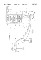
- FIG. 1 is a side view of a high-speed continuous-length belt conveyor delivering articles in a stabilized condition at high speeds to an optical inspection and sorting station in accordance with the invention
- FIG. 2 is a schematic block diagram of a control system which is part of the optical-inspection and sorting station shown in FIG. 1;
- FIG. 3 is a schematic block diagram of the image sorting engine shown in FIG. 2;
- FIG. 4 is a schematic illustration of an exemplary membership classification in RGB space used for initializing the color classifier 64 in FIG. 3;
- FIG. 5 is a schematic illustration of the implementation of the membership classification depicted in FIG. 4.
- FIG. 6 is a neural network implementation of the object classifier depicted in FIG. 3.
- FIG. 7 is an exemplary neural network configured to realize the object classifier of FIG. 6.
- FIGS. 8-11 depict various exemplary touch pad screen displays realized with an application pack of this invention including respective graphical sliders for adjusting corresponding sorting parameters and respective status displays for providing sorting statistics.
- FIG. 1 A preferred embodiment of a high-speed mass-flow food-sorting apparatus of this invention is illustrated in FIG. 1 and is generally designated with numeral 10.
- a conveyor 12 is designed to receive bulk articles 14 fed in a wide swath from a low-velocity bulk feeder 16 (such as a feeder shaker), stabilize the articles using centrifugal force, and convey the articles individually at a high velocity past an optical-inspection station 18 and a sorting station 20.
- a low-velocity bulk feeder 16 such as a feeder shaker
- Bulk feeder 16 is constructed and arranged to shake articles 14 so as to spread them out both laterally and longitudinally into a single layer having a wide swath.
- a discharge end 22 on the feeder discharges the articles in a wide swath from the feeder into free flight toward the conveyor 12 at a relatively low velocity.
- the articles 14 maintain a free flight trajectory 24 as they are discharged from the feeder to the conveyor.
- a personal computer 27 implements a control processor 26 and memory-based software to operate an array of imaging cameras 28 and an array of product diverters 72, or other mechanisms for removal of product from product flow, including knives.
- a higher-layer of software called an application pack 30 which includes a graphical user interface 32 and configuration software 36 is implemented on the personal computer.
- the application pack 30 allows an operator to easily configure, initialize, and control inspection and sorting operations carried out by the cameras and product diverters for a specific product such as peas, corn, beans, etc.
- the inspection station 18 is formed from the personal computer 27, including the application pack 30, and the cameras 28.
- the sorting station 20 is formed from the personal computer 27, including the application pack 30, and the product diverters 72.
- sorting shall refer to arranging items according to class, kind or size; classifying; separating items or portions of items one from the other, including cutting portions or segments of an item from a remaining body such as with a cutting wheel.
- sorting shall include machinery configured to implement automated defect removal (ADR, a registered trademark of Key Technology, Inc.), as well as other sorting, cutting and feature separating machinery and processes.
- ADR automated defect removal
- sorting shall refer to a separation of product based on differentiable visual characteristics, including the more limited sorting of "undesirable" characteristics from a product being sorted.
- the graphical user interface (GUI) 32 of the application pack 30 is implemented in software as shown in FIG. 2.
- the configuration software 36 and GUI 32 are loaded into the memory of the personal computer 27.
- the configuration software 36 when executed by the control processor 26, facilitates the configuration, setup, and initialization of the sorting apparatus for a particular product.
- An image sorting engine 54 provided in the form of hardware and software, is configured and initialized by the configuration software 36 to enable the sorter to classify colors, isolate desired properties, compute features, and classify objects for any specific sorting application.
- the GUI 32 when executed by the control processor 26, provides a graphical interface to the sorting machine and uses terms specific to the product being sorted and familiar to the operator.
- a touch pad display 50 displays a series of graphical sliders 52, an image-display window 51, and one or more status displays 80-83 as illustrated in FIGS. 8-11.
- a given slider can be easily adjusted by an operator to alter one or more sorting parameters which define differentiable visual characteristics on an article being sorted.
- the status displays 80-83 will preferably indicate various sorting statistics such as percentage of each class detected, percentage of each class removed, etc.
- visual characteristics are color-related, which are implemented with attributes; shape-related, which are implemented with properties; and/or size or feature location related including defect, which are implemented with features and feature thresholds.
- an attribute can be defined as a collection of points in red-green-blue space (RGB) space, which can be considered the same color for the sorting application at hand.
- RGB red-green-blue space
- an intensity independent color space such as HSI or LAB can be used.
- the color(s) that an operator considers "rot” on a green bean may include thousands of points in RGB space. This idea is illustrated by the rot color cloud 92 in FIG. 4.
- the color(s) that an operator considers "product flesh” (i.e. acceptable) on a green bean may include the thousands of points in the product-flesh color cloud 94.
- the color(s) that a sorter "sees” in the absence of any product, that is, the background color(s) may include the thousands of points in the "background” color cloud 93.
- Sorting applications can have a varying number of attributes and each attribute will have a corresponding color cloud in RGB-space.
- the color classifier 64 shown in both of FIGS. 3 and 5 will classify each 24-bit RGB pixel from color image 91 into exactly one of these attributes.
- the color classifier does this by creating a binary image, or "attribute image,” for each attribute from the 24-bit color image 91 that the color classifier processes.
- An attribute image is a single-bit "duplicate" of the 24-bit color image 91.
- An attribute image for a given attribute contains single-bit values which are enabled, i.e. their values are set equal to "1", only at those locations in the attribute image which correspond to locations in the original 24-bit color image containing RGB values that map inside the corresponding color cloud in RGB space.
- the attribute images created by color classifier 64 contain "blobs”, also referred to as "objects”, or spatially contiguous groups of pixels which need further processing by the property isolation process 68 in FIG. 3.
- This processing includes the isolation of object properties into separate binary images, or "property images.”
- a property can be defined as a collection of pixels on an object that characterize some aspect of the object's shape. For example, the pixels that are on an object's perimeter are a property of that object; the pixels that are on an arbitrarily thin part of an object are a property of that object; the pixels that surround a hole in an object are a property of that object; the pixels that are on an object's skeleton (which is the stick figure representation of the object) are a property of that object.
- Properties that can be isolated from an object are also objects in and of themselves in that they also are spatially contiguous groups of pixels.
- Attribute and property images created by color classifier 64 and property isolation processor 68 contain objects of spatially contiguous groups of pixels that need still further processing by the object classifier 70. This processing results in the computation and comparison of object features and feature combinations.
- a feature can be defined as a descriptor of shape orientation for an object and/or an indicator of object size. Examples of shape-orientation features are bounding box, bounding-box height, bounding-box width, bounding-box area, bounding-box area ratio, minimum radius, maximum radius, minimum radius angle, maximum radius angle, radius ratio, etc. Examples of size-indicator features are length, width, area, perimeter, etc . (Commonly understood definitions for the above-listed features are described in "Digital Image Processing", by William K.
- FIG. 2 shows a control system 38 which forms a part of the inspection station 18 and sorting station 20.
- the control system 38 includes the control processor 26, the application pack 30, an image sorting engine 54, a plurality of imaging cameras 28, the touch pad display 50, and the product diverters 72.
- the control processor 26 is preferably a Pentium microprocessor produced by Intel.
- the application pack 30, image sorting engine 54, and touch pad display 50 provide the primary elements of this device. Namely, the addition of application pack 30 significantly simplifies configuration, initialization, and adjustments of the sorting apparatus 10 for specific sorting operations by providing product-specific configuration software 36 and product-specific graphical sliders 52 for altering one or more sorting parameters, or combination of parameters which define undesirable visual characteristics on an article being sorted.
- FIG. 3 depicts in block-diagram form the processing pipeline provided by the sorting engine 54.
- the sorting engine is preferably implemented in a combination of hardware and software and includes an imaging camera 28, a color classifier 64, a property isolation processor 68, and an object classifier 70.
- the classifiers 64 and 70 and processor 68 are implemented in hardware and software to produce eject commands 86 that direct the product diverters 72 to sort out undesirable product during a sorting operation.
- one or more of the above items can be implemented in pure software or pure hardware.
- a single-camera implementation is depicted in FIG. 3, although the control processor 26 is preferably configured to handle multiple cameras that are laterally spaced across the path of moving food articles during optical inspection and sort operations.
- camera 28 is a line-scan true-color (24-bit RGB) video camera.
- any optical imaging device can be substituted for the camera, including a grey-scale video camera, a photocell device, a laser scanner, an ultraviolet camera, an infrared camera, a Magnetic Resonance Imaging (MRI) device, or a spectroscopic scanner.
- MRI Magnetic Resonance Imaging
- the sliders 52 provided by the application pack 30 can be adjusted via finger manipulation of the touch-pad display 50 by an operator or technician.
- the sliders 52 are operated on the principle of resistive or capacitive changes produced at the display 50 by the adjacent placement of an operator's finger.
- the sliders can be moved up and down in order to adjust a particular sorting parameter that alters either a desired sorting attribute, property, feature, or feature threshold, or a combination of one or more for a particular sort.
- a mouse 48, keyboard 46, track-ball 47, or light pen 49 can be provided to manipulate each "slider" when adjusting sorting parameters for a specific sorting operation.
- Each "slider” is a graphical implementation of a mechanical slider that can be adjusted by way of the touch-pad display from an operator's finger-contact with the slider.
- the slider which is visibly displayed on the touch-pad display can be picked by touching the display with an operator's finger, then dragging the finger either up or down the display to pull the slider to a desired position.
- the slider also includes a numerical display that indicates the value associated with the current slider position.
- a pair of directional arrows are provided at the top and bottom, respectively, such that an operator can touch either arrow in order to raise or lower the position of the slider.
- Personal computers typically have one or more CD drives that frequently include a sound board and speakers.
- One readily available graphical user interface includes a sound-equalizer that can be graphically displayed via the user-interface in order to adjust the frequency response characteristics of music that is played on the CD, through the sound board and speakers.
- Such a graphical user interface is analogous to mechanical analog sliders which in the past were provided on home stereo systems.
- touch-pad displays have also been utilized in the food industry in order to provide a pointing device other than a mouse or light pen that is suitable for the harsh food-plant environment.
- An operator can readily and easily configure and initialize the sorting apparatus 10 for a particular sorting operation simply by loading application pack 30, including GUI 32 and configuration software 36, into the memory of the personal computer 27.
- image sorting engine 54 is completely configured and initialized by configuration software 36 according to the requirements of the particular sorting operation for which the application pack was created.
- configuration software 36 and GUI 32 together form the application pack 30 which is provided on portable electronic media that is loaded into memory to become an integral part of the sorting apparatus 10.
- one application pack could be provided to uniquely configure and initialize the sorter for peas, a second for green beans, a third for carrots, and a fourth for french fries.
- a manufacturer can produce one sophisticated generic sorter 10 that is easily reconfigured by an operator to sort a particular product simply by loading an application pack into memory.
- FIG. 3 generally depicts a sorting machine with image sorting engine 54 implemented and control processor 26.
- the image sorting engine 54 incorporates many advanced image-processing capabilities that ordinarily would have to be initialized and controlled by a technician or "super operator” who is intimately familiar with the inner workings of the sorting apparatus 10.
- the application pack has all of the necessary configuration and initialization procedures built right in so that machine complexity is effectively hidden from the operator.
- configuration and initialization steps which are incorporated into the application pack include the pre-definition of all of the following items: color definitions for selected attributes, proper sequences of morphological operations for isolating required properties, sets of features to compute and corresponding feature thresholds against which to compare them, and definitions for categories into which each piece can be classified.
- the color classifier 64 of FIG. 3 is preferably implemented in a combination of hardware and software.
- the color classifier preferably categorizes 24-bit color pixels into one of several pre-defined binary attribute images. For example, as shown in FIG. 5, a stream of pixel data 56 representing a color image 91 of a scanned bean enters the color classifier 64. It then categorizes each one of these pixels into the correct binary attribute image according to the locations in RGB space at which the pixels' RGB values map as depicted in FIG. 4. Attribute images are shown in FIG. 5 for the attributes of rot 88, background 89, and product flesh 90. For example, the rot object 96 in the rot attribute image 88 indicates that the RGB values of the pixels in the corresponding locations in color image 91 map into the rot color cloud 92 in RGB space as depicted in FIG. 4.
- an operator In order to initialize a device such as color classifier 64 without the aid of application pack 30 of this invention, an operator typically must go through a series of steps. First he must specify the number of colors that are required for performing an effective sort for a particular sorting operation. These colors are then defined for the machine by the operator by identifying samples of 24-bit RGB values to include in each color definition. Upon defining all of the necessary colors, the definitions are then automatically converted to multidimensional mathematical functions which describe the definitions. At this stage, the color definitions are expanded and/or contracted by the operator who must input numerical scaling factors one-by-one for the corresponding mathematical functions. Typically, an operator working with a prior art device (having no application pack) described in U.S. Pat. No. 5,335,293, assigned to Key Technology, Inc., has to continuously adjust scaling factors until the 24-bit-RGB pixel values are correctly converted to the desired attributes.
- an application pack 30 for a specific product will have a pre-established set of colors each of which has been predefined and adjusted for optimal color classification.
- the configuration software 36 of application pack 30 will automatically configure the color classifier 64 according to the predefined colors.
- one or more graphical sliders 52 tied directly to numerical scaling factors described above may be provided by the GUI 32 of application pack 30 on touch-pad display 50. In this manner, the operator simply adjusts a slider 52 to robustify the color classification process when required; and the configuration software 36 will then make the appropriate changes in the color classifier 64. For example, the operator may want the sorter to eject more green-spotted product pieces. In this case, he simply adjusts a slider labelled perhaps "green spot" to increase the sorter's sensitivity to the colors characteristic of green spots and the configuration software 36 does the rest.
- Property isolation processor 68 shown in FIG. 3 is preferably implemented in a combination of hardware and software, wherein one or more types of multi-stage morphological and logical functions are performed.
- Morphological functions can be defined as operations in which the spatial form or structure of an object(s) is modified or ascertained. Types of morphological functions include pixel stacker, skeletonizer, erosion, dilation, and concatenated erosion/dilation pairs called open and close operations. Commonly understood definitions for the above-listed functions are described in Pratt, supra.
- the property isolation processor utilizes multi-stage morphological functions to isolate into binary property images those shape-related properties of interest from objects in binary attribute images.
- Examples of properties isolated with processor 68 include pixels on arbitrarily "thin" parts of objects, perimeter pixels of objects, perimeter pixels of holes in objects, pixels on an object's skeleton, as well as other form and/or structural characteristics that are derived by combining morphological and/or logical operations. As described earlier, properties are themselves objects because they are contiguous groups of pixels.
- Configuring the property isolation processor 68 for a particular product poses a daunting challenge even for the extremely rare operator specifically trained in morphological image processing.
- This configuration involves the specification of binary bit-masks and structuring elements (common to morphological image processing) which are specific to the product to be sorted.
- sequence of morphological functions to be applied in this multi-stage process must be configured into the property isolation processor.
- an application pack 30 for a specific product will have a pre-established set of binary bit-masks and structuring elements for the optimal isolation of the properties required for the product to be sorted.
- the configuration software 36 of application pack 30 When loaded into memory by the operator, the configuration software 36 of application pack 30 will automatically configure the property isolation processor 68 according to the pre-established bit-masks and structuring elements. Furthermore, the configuration software 36 will properly specify the sequence of morphological functions to be applied in any multi-stage processing that is required.
- One or more graphical sliders 52 each of which control one or more aspects of the property isolation processor may be provided by the GUI 32 of application pack 30 on touch-pad display 50.
- the operator simply adjusts a few sliders 52 to change the definition of the properties being isolated when required, and the configuration software 36 will then make the appropriate changes in the property isolation processor 68.
- the operator may want the sorter to eject product pieces with thicker plant stalk attached to them.
- he simply adjusts the slider labelled "stalk" to increase the sorter's sensitivity to it, and the configuration software 36 will adjust appropriate morphological structuring elements to redefine "thin” and then reconfigure the property isolation processor to isolate pixels on thicker areas of product pieces.
- Object classifier 70 of FIG. 3 is preferably implemented in a combination of hardware and software.
- the object classifier is preferably used to compute features and feature combinations and to compare these values against feature thresholds. Examples of features include bounding box, minimum radius, minimum radius angle, length, width, area, etc. Examples of feature combinations are circularity and center of gravity.
- the object classifier 70 is also preferably used to analyze feature locations on objects as some applications allow objects with defects in the middle, for example such as french fries, to pass through without being ejected to maintain a specific length distribution.
- the object classifier 70 first identifies as objects all spatially contiguous groups of pixels, i.e. blobs, in each binary attribute plane and each binary property plane. Then features and feature combinations appropriate for the particular articles being sorted are computed and compared against pre-established feature thresholds. The results of these comparisons affect which articles are classified as defective and which articles are ejected via eject commands 86. Note that the object classifier 70 can be configured to eject just enough of the pieces it has classified as defective so as to barely stay in grade, thereby increasing yield. Note also that the object classifier 70 supplies sorting statistics 74 to the control processor such as percentage of defects detected in incoming product stream, percentage of defects ejected, etc.
- Configuring the object classifier 70 typically involves specifying which features and feature combinations to compute, which feature and/or feature combinations require feature thresholds, how to logically combine comparison results in preparation for classifying pieces, how to classify pieces as defects, how to decide which defective pieces to actually eject, which sorting statistics are interesting to the operator, and how these statistics shall be displayed.
- An exemplary application pack 30 configured for a specific product will have a pre-established set of features and feature combinations to compute and a corresponding set of feature thresholds against which to compare results for defect and eject classification.
- the configuration software 36 of application pack 30 shown in FIG. 3 will automatically configure the object classifier 70 according to the pre-established feature set.
- One or more graphical sliders 52 which control some aspect of object classification may be provided by the GUI 32 of application pack 30 on touch-pad display 50 of FIGS. 8-11.
- the operator simply adjusts a few sliders 52, corresponding to, and labeled with, the typical terms operators in that industry would use for those characteristics, to change the manner in which product pieces are classified or sorting statistics are reported, and the configuration software 36 will then make the appropriate changes in the object classifier 70.
- the operator may want the sorter to eject fewer of the pieces it is classifying as rot defect because the current target grade allows more of these types of defects in the final product.
- he simply adjusts the slider labelled "rot" to decrease the sorter's sensitivity to it, and the configuration software 36 will adjust appropriate feature computations and/or comparisons in the object classifier to remove fewer of the product pieces which are being classified as rot defects.
- the object classifier 70 reports sorting statistics 74 to the control processor 26.
- the GUI 32 of application pack 30 can display these statistics in a variety of ways, depending on the product being sorted and the wishes of the operator. For example, status displays 80 and 81 of FIG. 6 indicate percentage of a defect called "bug bite" and percentage of defect-free beans, respectively. Another variation is depicted in FIG. 9 wherein the percentage of pieces with carrot cracks is indicated by status display 82 and the percentage of defect-free pieces is indicated by status display 83.
- the statistics reported by object classifier 70 can be used for automatic sorter parameter adjustments by statistical process control algorithms executing either on the control processor 26 or an external processor networked to the control processor 26.
- One alternative implementation to that depicted in FIG. 3 involves substitution of a statistical object classifier for the object classifier 70.
- the feedback information is delivered to the control processor 26 via the feedback loop 74 (indicated optionally in FIG. 3).
- One example of a statistical object classifier would involve implementing standard statistical pattern classification and scene analysis algorithms in order to characterize a population according to statistically observed features.
- FIG. 3 Another alternative implementation to that depicted in FIG. 3 involves substitution of a feature extractor 120, a neural network object classifier 121, and an eject processor 122 generally for the object classifier 70 of FIG. 3.
- One embodiment of this implementation of an application pack is depicted in FIG. 6 wherein the application pack supports the use of one or more forms of neural networks as the object classification mechanism.
- the feature extractor of FIG. 6 extracts feature vectors x 1 , x 2 , x 3 , . . . x n such as area length, perimeter, perimeter 2 /area, etc., descriptive of the object. These are fed to the input layer of neurons of the neural network object classifier 121, a type of multilayer perceptron.
- feature vectors x 1 , x 2 , x 3 , . . . x n such as area length, perimeter, perimeter 2 /area, etc.
- the neural network object classifier consists of a three layer, backpropagation network, with the input layer, x 1 -x n , consisting of one neuron for each of n features, a hidden layer consisting of n neurons, and an output layer consisting of one neuron for each of m output classes, o 1 -o m , corresponding to the m classes into which each object will be classified.
- the neurons possess a non-linear, preferably, a sigmoidal activation function.
- the backpropagation network is an established design wherein the backpropagation of error signals from the output layer is used to adjust the synaptic weights of input and hidden layers.
- Presentation of a series of sets of input patterns x 1 , x 2 , x 3 , . . . x n trigger a forward propagation of signals through the network and results in a set of output values, o 1 , o 2 , o 3 , . . . o m , corresponding to each of the m possible classes.
- the error between the output values o 1 , o 2 , o 3 , . . . o m calculated as a result of forward propagation, and the expected values for o 1 , o 2 , o 3 , . . .
- Backpropagation networks are well established, and some are available in commercial form, as hardware, software, or hardware/software hybrids such as the NeuralWorksTM Professional II/Plus from NeuralWare of Pittsburgh, Pa. An important benefit of backpropagation networks is their ability to generalize: they do not have to be presented with every possible input pattern during the training of the neural net.
- the application pack supplies the neural network extent, the number of layers and number of neurons, and the synaptic weights based on training.
- the application pack benefits by previous "training” and is immediately able to provide sophisticated object classification.
- the eject processor 122 of FIG. 6 assesses the outputs o 1 , o 2 , o 3 , . . . o m to determine whether or not to activate the ejection mechanism. In one embodiment, the object would be classified according to which output value has the highest value. If that class is intended to be separated from the product stream, the eject processor generates a corresponding eject command.
- Another implementation of the application pack uses a backpropagation neural network for control of the image sorting engine, distinct from, but possibly in addition to, using a neural network for the object classifier.
- the neural network is implemented as a control processor.
- the object classifier 70 of FIG. 3 has been constructed with the feature extractor 120, the neural network object classifier 121 and the eject processor 122.
- object features are listed as x 1 -x n , wherein x 1 is area, x 2 is length of a thin section, x 3 is a ratio of major versus minor axes, and x n is a ratio of (perimeter) squared/area.
- output values are indicated as follows: o 1 indicates good product, o 2 indicates rotted product, o 3 indicates stem product and o m indicates a foreign object.
- the feature extractor 120 extracts feature measurements x 1 -x n .
- the neural network 121 performs separation in n-tuple yielding output values o 1 -o m .
- the eject processor 122 evaluates o 1 -o m in order to test for a reject condition based on "best" classification into output values o 1 -o m . For example, a highest value, a lowest value, or boolean patterns.
- weighting values for the nodes as well as the neural network object classifier, preferably configured as shown in FIG. 7, are supplied as part of the application pack, and are configured for a given product being sorted.
- all application packs use one or more sliders.
- Each slider "maps" various positions of one or more movable boundaries in feature vector space against the linear position of the slider.
- this mapping can be complex and non-linear.
- this mapping is "learned" by the neural network in a manner similar to the above-described neural network object processor, as part of the application pack configuration.
- the output values o 1 , o 2 , o 3 , . . . o m rather than corresponding to object classes, consist of control values used to set various parameters of the image sorting engine, which may include inputs to the input layer of a neural network object classifier.
- the network is trained to generate the correct output pattern of control signals to the image sorting engine for a given input pattern of slider values.
- the benefit here is that very complex mappings can be accomplished based on training with real product, eliminating the need for extensive iterative attempts using regression or other statistical techniques, and providing the operator with a ready-to-run application.
- FIGS. 6 and 7 Actual physical implementation of devices according to FIGS. 6 and 7 can be as software running in the control processor 26 or as software running in a separate hardware neural network module.
- the sorting engine 54 of FIG. 3 can be configured to sort an exemplary vegetable generally referred to as a "luman" that characteristically has a very uniform orange color.
- a luman is an imaginary vegetable product.
- Alternative food products suitable for sorting would include legumes, peas, carrots, french fries, corn, peanuts and any other similar product.
- Lumans are characteristically found to have a single well known type of defect commonly referred to by customers as "rot". The presence of rot in a luman can be characterized by either black or green spots (or both).
- sorting apparatus 10 including sorting engine 54 to perform simple sorting operations for lumans
- the customer will typically want to control a single parameter defining the size of the rot pieces, or spots on luman that the sorter ejects from the stream of good product.
- the customer may also want to know the percentage of rot pieces detected by the sorter in the incoming product stream over time.
- the video display 50 via the graphical user interface 32 will have a single slider 52 that is labeled "ROT".
- the slider has a linear range of sensitivity between a minimum sensitivity level (i.e. no rot pieces are ejected) and a maximum sensitivity level (i.e. luman pieces are ejected if black and/or green spots of any size are detected).
- the slider implemented in software via the graphical user interface and displayed on display 50, will be tied directly to a "rot area" threshold used by the object processor 60 for classifying luman pieces as "rot".
- the display 50 of the application pack will preferably have a gauge-type display indicating the percentage of rot-defect pieces detected in the incoming product stream similar to status display 80 of FIG. 8.
- the color definitions are implemented via processor 26 through implementation of software 36 such that orange, black and green are the only colors of interest when sorting lumans. Therefore, the application-pack will have four pre-established color definitions: orange, black, green and a background.
- Such color recognition is already known in the art and has been implemented according to the previously referenced patents and patent applications assigned to Key Technology.
- rot pieces can have either black or green spots. Therefore, a simple application-pack of FIG. 4 will logically combine the black and green color definitions into one attribute called "rot". Furthermore, the resulting application pack will have two other attributes called “background” and “flesh”. Therefore, there will be a total of three attributes.
- the simple version of the application pack will have a single "rot area” threshold. This threshold will be used by the object classifier 70 to compare against areas of rot spots that are computed from the property isolation processor 68. Preferably, the application pack will provide (via a slider 52) direct control of the rot area threshold to an operator.
- the color classifier 64 will convert the 24-bit RGB camera values into either "background”, “flesh”, or "rot” by creating corresponding binary images for each attribute. For this pack no properties need be derived by the property isolation processor 68 from the three attributes. Finally, the object classifier 70 classifies product pieces based on analysis of objects detected in the attribute binary images.
- the labeled results for "rot” will be analyzed by the object classifier for rot "blobs" (i.e. contiguous rot pixels).
- the area of each rot blob will be computed by the object classifier 70.
- Each rot blob is then registered with a "parent” luman piece on which it was optically detected.
- the areas of the rot blobs are then compared against a "rot area” threshold, set by an operator with a slider 52. All luman pieces having rot blobs larger than the rot area threshold are subsequently classified as defects and are ejected by a product diverter 72 according to one of the previously mentioned sorting devices developed by Key Technology.
- the object classifier 70 also periodically updates the control processor with the number of rot pieces and good pieces it has detected since the last update via feedback 74.
- the control processor then computes the percentage of rot pieces in the incoming product stream and preferably displays it on the rot gauge contained on display 50.
- a simple movement of slider 52 affects sorting machine 54 by changing the rot area threshold in the top-level application pack window 50.
- FIG. 3 can also be configured with sorting engine 54 incorporating a specific application pack 30 having an intermediate level of sophistication.
- the customer may also want to control the size of the rot pieces that the sorter actually classifies as being defective.
- the increased level and sophistication allows a customer to let a certain amount of defective product pass through the sorter in order to increase overall effective yield for times where a limited amount of defective product is acceptable. For example, certain customers may accept a limited amount of defective product according to their product requirements. In all cases, the total number of pieces that are actually ejected by sorting apparatus 10 will always be less-than or equal-to the number of pieces that are being classified as defective by the sorting engine 54.
- a sorting engine 54 that allows a first-level operator to control which rot defects are actually ejected by adjusting a slider 52, yet will allow a supervisor-type operator to control which rot pieces are classified as defective by adjusting a password-protected slider 52.
- a supervisory-type operator can access the software 36 in order to implement such commands via a software-based and display-accessible security access code.
- a first-level operator will be able to adjust rot defects actually ejected, yet will not be able to change the definition of rot defects.
- the customer may want to know the percentage of rot defects detected by the sorter in the incoming product stream over time as well as the percentage of rot defects that are actually ejected.
- the touch-pad display 50 will have a single slider 52 labeled "Rot" having an adjustable range from a minimum sensitivity level (i.e. no rot pieces are ejected) and a maximum sensitivity level (i.e. luman pieces are ejected if black or green spots of any size are detected).
- slider 52 will be tied directly to a "rot-eject area” threshold used by the object processor 70 to select which rot defects to eject.
- window portion 51 of touch-pad display 50 will have a gauge-type similar to displays 80-83 of FIGS. 8 and 11 indicating the percentage of rot defects detected in the incoming product stream as well as a gauge-type display indicating the percentage of rot defects in the incoming product stream that are actually ejected by the sorter.
- An intermediate level application pack will also have a second-level window within graphical user interface 32 that can be displayed on touch pad display 50 and that has a single slider labeled "MINIMUM ROT SIZE". However, this second-level window is only accessible via a supervisory security access code as discussed above.
- This limited-access slider will be directly tied to a "rot-defect area” threshold used by the object classifier 70 for classifying luman pieces as "rot". In this implementation, it is important to note several things. First, the "rot-defect area” threshold serves as a lower bound for the "rot-eject area” threshold. Secondly, every rot piece that is ejected will have first been classified as rot defects by the object classifier 70.
- every luman piece classified as a rot defect by the object classifier will be ejected if and only if "rot-eject area” threshold equals “rot-defect area” threshold; if "rot-eject area” threshold is greater than “rot-defect area” threshold, then a subset of the luman pieces classified as rot defects by the object classifier will be ejected.
- the exemplary intermediate application pack has only three colors of interest; namely, orange, black and green. Therefore, the application pack will have four pre-established color definitions: orange, black, green, and background.
- the intermediate application pack like the simple application pack, will logically combine black and green color definitions into one feature called "rot", because rot pieces in lumans can have either black or green spots.
- the application pack will have two other attributes called “background” and "flesh”. Thus, there will be a total of three attributes. For this pack, no properties need be derived by the property isolation processor 68 from the three attributes.
- Thresholds are set by control processor 26 via the application pack 30 similar to the previous example of a simple application pack.
- a "rot eject area” threshold is provided. This threshold is used by the object classifier 70 to compare the threshold level of "rot-eject area” against rot areas that are computed from objects in the "rot" binary image in order to determine which pieces to eject.
- the application pack will provide (via a slider in touch pad display 50) direct control to the s rot-eject area threshold to an operator.
- the application pack will also have a "rot-defect area” threshold.
- This threshold will be used by the object processor in order to compare the "rot-defect area” threshold against rot areas that are computed from objects in the "rot" binary image in order to determine which pieces to classify as rot defects.
- the application pack in this case will provide access to a slider 52 in a second-level window which is only accessible to a supervisory operator via a password and security code. Therefore, direct control of the rot-defect area threshold is also available on a slider, but it can only be accessed by a supervisory operator via a security code.
- the color classifier 64 of the intermediate level application pack will convert the 24-bit RGB camera values into either "background”, “flesh” or “rot” by creating corresponding binary images for each attribute.
- the "rot" binary image is analyzed to detect rot "blobs”.
- Classifier 70 then computes the area of each detected rot blob.
- Each rot blob is then registered, or mapped with its respective "parent" luman piece.
- the areas of the rot blobs are compared against the rot-eject and rot-defect area thresholds. All luman pieces having rot blobs larger than the rot-defect area threshold are classified as rot defects.
- all luman pieces having rot blobs larger than the rot-eject area threshold are classified as rot defects and are ejected by the product diverter 72. All other luman pieces are subsequently allowed to pass through.
- the object classifier 70 periodically updates the control processor 26 with the number of rot pieces it has detected in the incoming product stream, the number of pieces it has actually ejected, as well as the number of good pieces it has detected since the last update.
- the control processor 26 furthermore computes the percentage of rot pieces in the incoming product stream and the percentage of the rot pieces that have been ejected, and furthermore displays these values on corresponding gauges that can be displayed on touch pad display 50 via selection of an appropriate display through graphical user interface 32.
- the rot-eject area threshold is tied directly to a slider 52 in the top-level application pack accessible by an operator.
- the rot-defect area threshold is tied directly to a corresponding slider 52 only accessible in a second-level graphical user interface window by a supervisory operator.
- FIG. 3 can also be configured as an advanced level application pack 30 having a higher level of complexity.
- the customer may want to control the size of rot pieces that the sorter ejects, as well as the size of rot pieces that the sorter actually classifies as a defect, similar to what was done in the intermediate application pack.
- the number of pieces that are actually ejected will always be less-then or equal-to the number of pieces that are classified as a defect.
- the customer wants only a supervisor-type of operator to adjust the threshold that defines what pieces are rot defects and wants a simpler operator who actually operates the apparatus 10 during sorting to adjust the maximum allowed percentage of rot in the accepted stream.
- the customer wants to know the percentage of rot defects detected by the sorter in the incoming product stream over time, the percentage of rot defects that are actually ejected, as well as the percentage of rot defects in the accept (or acceptable) stream of product.
- luman stems are characteristically thin when compared with the actual luman piece.
- the customer may want to control the length of the stem that the sorter ejects, as well as the length of the stems that the sorter actually classifies as a stem. In this case, the number of pieces that are actually ejected because of stem length will always be less-then or equal-to the number of pieces that are classified as having a stem.
- the customer may want only a supervisor-type operator to adjust the threshold that defines how long a "thin" luman piece has to be before it is classified as a stem, and the customer may want a operator with less responsibility of authority to adjust the maximum allowed percentage of pieces with stems delivered in the accepted stream.
- the customer furthermore wants to know the percentage of pieces with stems detected by the sorter in the incoming product stream over time, the percentage of these stem defects that are ejected, and the percentage of pieces with stems in the accept stream.
- the touch pad display 50 of the application pack 30 will preferably have a slider labeled "ROT PERCENTAGE ALLOWED" which will specify to the sorting apparatus 10 the maximum allowable percentage of rot pieces in the accept stream.
- the slider 52 will be tied directly to the target value of a statistical process control algorithm executed on the control processor 26 and receiving feedback on classification via feedback loop 74 as shown in FIG. 3.
- the algorithm will preferably continuously update a "rot-eject area" threshold used by the object classifier 70 for selecting which rot defects to eject.
- the touch-pad display 50 of the application pack will have a gauge-type display similar to displays 80-83 in FIGS.
- the touch-pad display 50 of the application pack 30 will also have a slider 52 labeled "stem percentage allowed" which will specify to the sorter 10 the maximum allowable percentage of pieces with stems in the accept stream.
- This slider will be tied directly to the target value of a statistical process control algorithm executing on control processor 26. This algorithm will continuously update a "stem-eject length" threshold used by the object processor for selecting which stem defects to eject.
- the touch-pad display 50 of the application will have a gauge-type display indicating the percentage of stem defects detected in the incoming product stream, a gauge-type display indicating the percentage of stem defects in the incoming product stream that are actually ejected by the sorter, and a gauge-type display indicating the percentage of stem pieces in the accept product stream.
- each of the displays can be brought up individually, or in combination via reconfiguration of screens with the graphical user interface 32.
- the advanced application pack 30 of FIG. 6 will also have a second-level window (accessible only via a supervisory security code password) which has a slider 52 labeled "MINIMUM ROT SIZE". This slider will be directly tied to a "rot-defect area" threshold used by the object classifier 70 for classifying luman pieces as "rot".
- the "rot area defect” threshold will serve as a lower bound for the "rot area eject” threshold.
- all rot pieces ejected will have first been classified as rot defects by the object classifier 70.
- all luman pieces classified as rot defects by the object classifier 70 will be ejected if and only if "rot area eject" threshold equals "rot area defect” threshold. If the "rot area eject" threshold is greater than "rot area defect” threshold, then a subset of the luman pieces classified as rot defects by the object classifier 70 will be ejected.
- a third slider 52 will also be provided in the sorting engine 54 of the advanced application pack.
- a slider 52 labeled "MINIMUM STEM SIZE” will also be provided in the second-level window.
- This slider will be directly tied to a "stem-defect length” threshold used by the object classifier 70 for classifying luman pieces as "stem pieces” (i.e. pieces with stems).
- the sorting engine 54 in the advanced application pack 30 will distinguish orange, black and green, which are the only colors of interest in this example. Therefore, the application pack has four-established color definitions: Orange, black, green and background.
- the attributes depicted in the advanced application pack are the same as those depicted in the simple example. Specifically, because rot pieces can have either black or green spots, the application pack will logically combine the black and green color definitions into a single attribute called "rot". Furthermore, the application pack has two other attributes called “background” and "flesh”. Hence, there will be a total of three attributes in this application pack.
- the application pack will have a pre-set sequence of morphological operations that it uses to initialize the property isolation processor 68 for isolating stem properties.
- the property isolation processor 68 will then create a binary image containing only those pixels on the "thin” areas of objects in the "background” binary image.
- Stems isolated by processor 68 will later be “registered” along with defective rot spots with "parent" luman pieces, by object classifier 70.
- the centers of the defective luman pieces will then be computed so that ejection air-blasts can be aimed at the actual luman piece centers from the product diverter 72.
- the threshold criteria for the sorting engine 54 in the exemplary advanced application pack follows similar to that for the simple application pack.
- the application pack 30 will have a "rot-eject area” threshold. However, the operator will not have direct control over threshold via the slider 52. In this case, the rot-eject threshold will still be used by the object classifier 70 to compare against rot areas in the "rot" binary image in order to determine which pieces to eject.
- the application pack will automatically and continuously internally adjust the rot-eject area threshold as part of an internally integrated statistical process control algorithm 76 implemented by control processor 26 via feedback 74 which uses a target percentage (of allowable rot in the accept stream) as specified by an operator via a slider 52. Additionally, the application pack will have a "rot-defect area” threshold.
- This threshold will be used by the object classifier to compare against rot areas that are computed from the "rot" binary image in order to determine which pieces to classify as rot defects.
- a slider 52 will be provided for this threshold in the application pack in a second-level window accessible to a supervisory operator via a password security code. In this manner, a supervisory operator can have direct control of the rot-defect area threshold.
- Another threshold provided in the sorting engine 54 for the advanced application pack consists of a "stem-eject length” threshold.
- the stem-eject threshold will still be used by the object classifier 70 to compare against stem lengths that are computed from the stem binary image in order to determine which pieces to eject.
- the application pack itself will automatically continuously adjust the stem-eject length threshold as part of a statistical process control algorithm either similar to or the same as algorithm 74 which uses a target percentage (of allowable stemmed pieces in the accept stream) specified by an operator via a slider 52.
- the application pack will also have a "stem-defect length" threshold.
- the aforementioned threshold will be used by the object classifier 70 to compare against stem lengths that it computes from the stem binary image in order to determine which pieces to classify as stem defects.
- the application pack 30 will preferably provide a slider 52 in its second-level window accessible by a supervisory operator in order to directly control the stem-defect length threshold.
- the color classifier of FIG. 3 will convert the 24-bit RGB camera values 56 into either "background”, “flesh”, or "rot” by creating corresponding binary images for each attribute.
- Property isolation processor 68 isolates into a stem binary image the thin parts of the objects in the background binary image, and the isolated results are passed onto the object classifier 70.
- the object classifier 70 of FIG. 3 analyzes the "rot" binary image in order to detect rot "blobs". The object classifier then computes the area of each detected rot blob. The rot blobs are then registered with their "parent" luman pieces. The areas of the rot blobs are then compared against the rot-eject as well as the rot-defect area thresholds. All luman pieces having rot blobs larger than the rot-defect area threshold are classified as rot defects. All luman pieces having rot blobs larger than the rot-eject area threshold are classified as rot defects and are ejected by the product diverter 72. All other luman pieces are allowed to pass through as acceptable product during a sorting operation.
- the object classifier 70 periodically updates the control processor 26 with the number of rot pieces that have been detected in the incoming product stream, the number of rot pieces that have actually been ejected, and the number of good pieces that have been detected since the last update.
- the controlled processor 26 then computes the percentage of rot pieces in the incoming product stream and the percentage of rot pieces that have been ejected, afterwhich the respective values are displayed on corresponding gauges preferably accessible through the graphical user interface 32 for display on touch pad display 50.
- the control processor in this embodiment uses computed percentages in a statistical process control algorithm 76 to figure out the continuous adjustment to the rot-eject area threshold.
- the rot-defect area threshold is manipulated directly by a dedicated slider 52 in a second-level application pack window accessible only by a supervisory operator, for example by coded activation of one or more of buttons 78.
- the stem binary image is also analyzed by object classifier 70 for "stem blobs" by the object classifier 70.
- the object classifier then computes the length of each detected stem blob.
- Stem blobs are then registered with their "parent" luman pieces.
- the length of each stem blob is then compared against both the stem-eject as well as the stem-defect length thresholds. All luman pieces having stems longer than the stem-defect length of threshold are then classified as stem defects. All luman pieces with stems longer then the stem-eject area threshold are classified as stem defects and are subsequently ejected. All remaining luman pieces are allowed to pass through the sorting apparatus 10.
- the object classifier 70 periodically updates the control processor 26 with the number of stem pieces that have been detected in the incoming product stream, the number of stem pieces that have actually been ejected, and the number of good pieces that have been detected since the last update.
- the control processor 26 then preferably computes the percentage of stem pieces in the incoming product stream and the percentage of stem pieces that have been ejected, and furthermore, displays these values on corresponding gauges similar to displays 80-83 of FIGS. 8 and 11 implemented via the graphical user interface 32 on touch pad display 50.
- the control processor 26 uses the computed percentages in a statistical process control algorithm in order to figure out how to continuously adjust the stem-eject length threshold.
- the stem-defect length threshold is tied directly to a dedicated slider 52 in the second-level application pack window accessible only by a supervisory operator.
- the general sorting system including the sorting engine 54 provided in part by application pack 30 has readily adaptable and easily utilized capabilities such that use by a simple operator is readily performed on the device generally depicted in FIG. 3. Yet, with the three example application packs discussed above, this general sorting system can be "packaged" in a manner which appears to a customer like an easy-to-use sorter designed specifically for the customer and the customer's particular product sorting operation. This feature, in combination with the ease of use that the application pack 30 will provide a customer by hiding unnecessary machine complexities to a simple user, constitutes the main contribution of the apparatus and method of this invention.
- FIGS. 8-11 depict various exemplary touch pad screen displays 50 with a graphical user interface of this invention.
- FIG. 8 depicts display 50 configured for sorting beans.
- FIGS. 9 and 10 depict screen display 50 for sorting defects in french fries.
- FIG. 11 depicts screen display 50 configured for sorting carrots.
Abstract
Description
Claims (25)
Priority Applications (1)
| Application Number | Priority Date | Filing Date | Title |
|---|---|---|---|
| US08/884,930 US5887073A (en) | 1995-09-01 | 1997-06-30 | High speed mass flow food sorting apparatus for optically inspecting and sorting bulk food products |
Applications Claiming Priority (2)
| Application Number | Priority Date | Filing Date | Title |
|---|---|---|---|
| US08/522,944 US5659624A (en) | 1995-09-01 | 1995-09-01 | High speed mass flow food sorting appartus for optically inspecting and sorting bulk food products |
| US08/884,930 US5887073A (en) | 1995-09-01 | 1997-06-30 | High speed mass flow food sorting apparatus for optically inspecting and sorting bulk food products |
Related Parent Applications (1)
| Application Number | Title | Priority Date | Filing Date |
|---|---|---|---|
| US08/522,944 Continuation US5659624A (en) | 1995-09-01 | 1995-09-01 | High speed mass flow food sorting appartus for optically inspecting and sorting bulk food products |
Publications (1)
| Publication Number | Publication Date |
|---|---|
| US5887073A true US5887073A (en) | 1999-03-23 |
Family
ID=24083016
Family Applications (2)
| Application Number | Title | Priority Date | Filing Date |
|---|---|---|---|
| US08/522,944 Expired - Fee Related US5659624A (en) | 1995-09-01 | 1995-09-01 | High speed mass flow food sorting appartus for optically inspecting and sorting bulk food products |
| US08/884,930 Expired - Fee Related US5887073A (en) | 1995-09-01 | 1997-06-30 | High speed mass flow food sorting apparatus for optically inspecting and sorting bulk food products |
Family Applications Before (1)
| Application Number | Title | Priority Date | Filing Date |
|---|---|---|---|
| US08/522,944 Expired - Fee Related US5659624A (en) | 1995-09-01 | 1995-09-01 | High speed mass flow food sorting appartus for optically inspecting and sorting bulk food products |
Country Status (8)
| Country | Link |
|---|---|
| US (2) | US5659624A (en) |
| EP (1) | EP0847563B1 (en) |
| AT (1) | ATE367617T1 (en) |
| AU (1) | AU6895896A (en) |
| BR (1) | BR9610335A (en) |
| CA (1) | CA2230784C (en) |
| DE (1) | DE69637172T2 (en) |
| WO (1) | WO1997009689A1 (en) |
Cited By (55)
| Publication number | Priority date | Publication date | Assignee | Title |
|---|---|---|---|---|
| EP0847563A1 (en) * | 1995-09-01 | 1998-06-17 | Key Technology, Inc. | A high speed mass flow food sorting apparatus for optically inspecting and sorting bulk food products |
| US6243491B1 (en) * | 1996-12-31 | 2001-06-05 | Lucent Technologies Inc. | Methods and apparatus for controlling a video system with visually recognized props |
| US6408429B1 (en) * | 1997-01-17 | 2002-06-18 | Cognex Corporation | Machine vision system for identifying and assessing features of an article |
| US20020181778A1 (en) * | 2001-04-04 | 2002-12-05 | Mitsubishi Electric Research | Method for determining compactness ratios of multiple data and signal sets |
| US20030043175A1 (en) * | 2001-08-27 | 2003-03-06 | National Instruments Corporation | System and method for specifying a machine vision process using dfferent programming methodologies |
| US6600829B1 (en) * | 1998-02-20 | 2003-07-29 | Sunkist Growers Inc. | Computer process for controlling a system for sorting objects by surface characteristics |
| EP1389301A1 (en) * | 2001-05-21 | 2004-02-18 | Pressco Technology, Inc. | An apparatus and method for providing snapshot action thermal infrared imaging within automated process control article inspection applications |
| US6701001B1 (en) | 2000-06-20 | 2004-03-02 | Dunkley International, Inc. | Automated part sorting system |
| US6711461B2 (en) * | 2001-03-20 | 2004-03-23 | Lockheed Martin Corporation | Object and method for accessing of articles for reliable knowledge of article positions |
| US20040091135A1 (en) * | 2002-11-07 | 2004-05-13 | Bourg Wilfred M. | Method for on-line machine vision measurement, monitoring and control of product features during on-line manufacturing processes |
| US6805245B2 (en) | 2002-01-08 | 2004-10-19 | Dunkley International, Inc. | Object sorting system |
| US20050180642A1 (en) * | 2004-02-12 | 2005-08-18 | Xerox Corporation | Systems and methods for generating high compression image data files having multiple foreground planes |
| US20060088196A1 (en) * | 2004-10-25 | 2006-04-27 | Popovich Joseph Jr | Embedded imaging and control system |
| US20060104535A1 (en) * | 2002-12-05 | 2006-05-18 | Christiaan Varekamp | Method and apparatus for removing false edges from a segmented image |
| US20060110048A1 (en) * | 2004-10-18 | 2006-05-25 | Laurent Charlin | System and method for characterizing 2-dimensional shapes by compactness measurements |
| US7386167B2 (en) * | 2004-07-21 | 2008-06-10 | Dainippon Screen Mfg. Co., Ltd. | Segmentation technique of an image |
| US20080279994A1 (en) * | 2003-02-21 | 2008-11-13 | Catherine Sarah Cantley | Method for reducing acrylamide formation in thermally processed foods |
| US20090120848A1 (en) * | 2006-04-06 | 2009-05-14 | Wacker Chemie Ag | Device and method for the flexible classification of polycrystalline silicon fragments |
| US20090251536A1 (en) * | 2006-04-04 | 2009-10-08 | 6511660 Canada Inc. | System and method for identifying and sorting material |
| US7768643B1 (en) | 2006-03-30 | 2010-08-03 | Key Technology, Inc. | Apparatus and method for classifying and sorting articles |
| WO2010107495A1 (en) * | 2009-03-19 | 2010-09-23 | Key Technology, Inc. | Sorting apparatus and method utilizing a mechanical diverter |
| US7842896B1 (en) | 2007-04-25 | 2010-11-30 | Key Technology, Inc. | Apparatus and method for sorting articles |
| WO2011007117A1 (en) * | 2009-07-16 | 2011-01-20 | Buhler Sortex Ltd. | Inspection apparatus and method using pattern recognition |
| US20110043621A1 (en) * | 2009-08-19 | 2011-02-24 | Keyence Corporation | Image Processing Device And Image Processing Method |
| WO2011028447A1 (en) * | 2009-08-25 | 2011-03-10 | Frito-Lay North America, Inc. | Method for real time detection of defects in a food product |
| US20110068051A1 (en) * | 2009-05-22 | 2011-03-24 | 6358357 Canada Inc. | Ballistic separator |
| US8124160B2 (en) | 2003-02-21 | 2012-02-28 | Frito-Lay North America, Inc. | Method for reducing acrylamide formation in thermally processed foods |
| US8158175B2 (en) | 2008-08-28 | 2012-04-17 | Frito-Lay North America, Inc. | Method for real time measurement of acrylamide in a food product |
| EP2418020A3 (en) * | 2010-08-11 | 2012-05-09 | OptiServe B.V. | Sorting device and method for separating products from a random strem of bulk inhomogeneous products |
| US20120136460A1 (en) * | 2010-11-29 | 2012-05-31 | Albert Handtmann Maschinenfabrik Gmbh & Co. Kg | Scalable machine |
| US20120138512A1 (en) * | 2009-03-19 | 2012-06-07 | Key Technology, Inc. | Sorting apparatus and method utilizing a mechanical diverter |
| US8406919B1 (en) * | 2010-03-12 | 2013-03-26 | Key Technology, Inc. | Quality regulating apparatus and method |
| WO2013103449A1 (en) * | 2011-11-16 | 2013-07-11 | Grant Kannan | System and method for automated inspecting and sorting of agricultural products |
| US8486684B2 (en) | 2007-08-13 | 2013-07-16 | Frito-Lay North America, Inc. | Method for increasing asparaginase activity in a solution |
| US8762851B1 (en) * | 2003-03-17 | 2014-06-24 | West Interactive Corporation Ii | Graphical user interface for creating content for a voice-user interface |
| EP2808096A1 (en) * | 2013-05-30 | 2014-12-03 | Panasonic Corporation | Separation apparatus and separation method |
| US9073091B2 (en) | 2013-03-15 | 2015-07-07 | Altria Client Services Inc. | On-line oil and foreign matter detection system and method |
| US9080987B2 (en) | 2011-05-26 | 2015-07-14 | Altria Client Services, Inc. | Oil soluble taggants |
| US9095145B2 (en) | 2008-09-05 | 2015-08-04 | Frito-Lay North America, Inc. | Method and system for the direct injection of asparaginase into a food process |
| US9097668B2 (en) | 2013-03-15 | 2015-08-04 | Altria Client Services Inc. | Menthol detection on tobacco |
| US9215886B2 (en) | 2008-12-05 | 2015-12-22 | Frito-Lay North America, Inc. | Method for making a low-acrylamide content snack with desired organoleptical properties |
| US20160001328A1 (en) * | 2013-03-14 | 2016-01-07 | Finatec Holding Ag | Device and method for transporting and examining fast-moving objects to be treated |
| US20160016203A1 (en) * | 2014-07-21 | 2016-01-21 | Minesense Technologies Ltd. | High capacity separation of coarse ore minerals from waste minerals |
| US9244017B2 (en) | 2011-05-26 | 2016-01-26 | Altria Client Services Llc | Oil detection process and apparatus |
| US20170036245A1 (en) * | 2015-08-03 | 2017-02-09 | Linear Group Services, LLC | Inspection and sorting machine |
| US20170120301A1 (en) * | 2015-11-04 | 2017-05-04 | Leadot Innovation, Inc. | Electronic product sorting system and sorting method |
| CN106767449A (en) * | 2016-12-28 | 2017-05-31 | 云南昆船设计研究院 | The uniformity of tobacco leaf distinguishes choosing method and device |
| CN110125047A (en) * | 2019-06-21 | 2019-08-16 | 北京智教未来科技有限公司 | A kind of intelligent color lump sorter based on color identification |
| US10512942B2 (en) * | 2017-10-30 | 2019-12-24 | Optisort, Llc | System and method for sorting objects |
| US10782279B2 (en) | 2014-11-11 | 2020-09-22 | Altria Client Services Llc | Method for detecting oil on tobacco products and packaging |
| US10900897B2 (en) | 2012-05-29 | 2021-01-26 | Altria Client Services Llc | Oil detection process |
| WO2021033012A1 (en) * | 2019-08-20 | 2021-02-25 | P & P Optica Inc. | Devices, systems and methods for sorting and labelling food products |
| US20210100256A1 (en) * | 2019-10-02 | 2021-04-08 | Prospection Solutions, LLC | Foreign Material Inspection System |
| US20210250519A1 (en) * | 2018-06-09 | 2021-08-12 | Sudeep Sundaram | Simultaneous inspection of multiple surfaces of an object |
| US11351576B2 (en) * | 2019-06-05 | 2022-06-07 | X Development Llc | Determining ore characteristics |
Families Citing this family (80)
| Publication number | Priority date | Publication date | Assignee | Title |
|---|---|---|---|---|
| JP3406760B2 (en) * | 1996-01-26 | 2003-05-12 | 株式会社東芝 | Monitoring and control equipment |
| US5818953A (en) * | 1996-04-17 | 1998-10-06 | Lamb-Weston, Inc. | Optical characterization method |
| US5986230A (en) * | 1996-09-13 | 1999-11-16 | Uncle Ben's, Inc. | Method and apparatus for sorting product |
| US6056127A (en) * | 1996-10-28 | 2000-05-02 | Sortex Limited | Delivery system for sorting apparatus |
| US6075882A (en) * | 1997-06-18 | 2000-06-13 | Philip Morris Incorporated | System and method for optically inspecting cigarettes by detecting the lengths of cigarette sections |
| US7212654B2 (en) * | 1997-06-20 | 2007-05-01 | Dawn Foods, Inc. | Measurement of fruit particles |
| US7130834B2 (en) | 1997-12-12 | 2006-10-31 | Idaho Potato Commission | Identification system and method for determining the geographic origin of a fresh commodity |
| US6324531B1 (en) * | 1997-12-12 | 2001-11-27 | Florida Department Of Citrus | System and method for identifying the geographic origin of a fresh commodity |
| US6067376A (en) * | 1998-01-16 | 2000-05-23 | Cognex Corporation | Classifying pixels of an image |
| US6013915A (en) * | 1998-02-10 | 2000-01-11 | Philip Morris Incorporated | Process control by transient thermography |
| US6610953B1 (en) * | 1998-03-23 | 2003-08-26 | University Of Arkansas | Item defect detection apparatus and method |
| US6201885B1 (en) | 1998-09-11 | 2001-03-13 | Bunge Foods Corporation | Method for bakery product measurement |
| US6155489A (en) * | 1998-11-10 | 2000-12-05 | Ncr Corporation | Item checkout device including a bar code data collector and a produce data collector |
| US6332573B1 (en) | 1998-11-10 | 2001-12-25 | Ncr Corporation | Produce data collector and produce recognition system |
| US6410872B2 (en) * | 1999-03-26 | 2002-06-25 | Key Technology, Inc. | Agricultural article inspection apparatus and method employing spectral manipulation to enhance detection contrast ratio |
| US6431446B1 (en) | 1999-07-28 | 2002-08-13 | Ncr Corporation | Produce recognition system and method |
| KR100374046B1 (en) | 1999-09-30 | 2003-03-03 | 오므론 가부시키가이샤 | Image Processing Apparatus, Image Processing Method and Visual Inspection System |
| US20010048765A1 (en) * | 2000-02-29 | 2001-12-06 | Steven Yi | Color characterization for inspection of a product having nonuniform color characteristics |
| JP4561944B2 (en) | 2000-06-16 | 2010-10-13 | 株式会社サタケ | Granule sorter |
| JP2003205269A (en) * | 2001-11-09 | 2003-07-22 | Satake Corp | Optical detecting means in granule color sorter |
| JP2003170122A (en) * | 2001-12-06 | 2003-06-17 | Satake Corp | Machine for sorting of granular material by color |
| NL1021026C2 (en) * | 2002-07-08 | 2004-01-09 | Havatec B V | Method and equipment for sorting flower bulbs and for separation of those found faulty employ X-ray radiation |
| US7340084B2 (en) * | 2002-09-13 | 2008-03-04 | Sortex Limited | Quality assessment of product in bulk flow |
| US7660440B2 (en) * | 2002-11-07 | 2010-02-09 | Frito-Lay North America, Inc. | Method for on-line machine vision measurement, monitoring and control of organoleptic properties of products for on-line manufacturing processes |
| US7190813B2 (en) * | 2003-01-15 | 2007-03-13 | Georgia Tech Research Corporation | Systems and methods for inspecting natural or manufactured products |
| JP4344164B2 (en) * | 2003-04-18 | 2009-10-14 | 株式会社サタケ | Piezoelectric air valve and composite piezoelectric air valve |
| JP4438358B2 (en) * | 2003-09-04 | 2010-03-24 | 株式会社サタケ | Granular color sorter with display adjustment mechanism |
| CN104392292B (en) * | 2004-05-21 | 2019-07-26 | 派拉斯科技术公司 | Graphical re-inspection user setup interface |
| US20060081135A1 (en) * | 2004-08-16 | 2006-04-20 | Britton Douglas F | Industrial overline imaging system and method |
| WO2007070361A2 (en) | 2005-12-06 | 2007-06-21 | St. Jude Medical, Atrial Fibrillation Division, Inc. | Assessment of electrode coupling for tissue ablation |
| US8406866B2 (en) | 2005-12-06 | 2013-03-26 | St. Jude Medical, Atrial Fibrillation Division, Inc. | System and method for assessing coupling between an electrode and tissue |
| US9254163B2 (en) | 2005-12-06 | 2016-02-09 | St. Jude Medical, Atrial Fibrillation Division, Inc. | Assessment of electrode coupling for tissue ablation |
| US20090177111A1 (en) * | 2006-12-06 | 2009-07-09 | Miller Stephan P | System and method for displaying contact between a catheter and tissue |
| US10362959B2 (en) | 2005-12-06 | 2019-07-30 | St. Jude Medical, Atrial Fibrillation Division, Inc. | System and method for assessing the proximity of an electrode to tissue in a body |
| EP1962710B1 (en) | 2005-12-06 | 2015-08-12 | St. Jude Medical, Atrial Fibrillation Division, Inc. | Apparatus for displaying catheter electrode-tissue contact in electro-anatomic mapping and navigation system |
| US8603084B2 (en) | 2005-12-06 | 2013-12-10 | St. Jude Medical, Atrial Fibrillation Division, Inc. | System and method for assessing the formation of a lesion in tissue |
| US9492226B2 (en) * | 2005-12-06 | 2016-11-15 | St. Jude Medical, Atrial Fibrillation Division, Inc. | Graphical user interface for real-time RF lesion depth display |
| US8403925B2 (en) | 2006-12-06 | 2013-03-26 | St. Jude Medical, Atrial Fibrillation Division, Inc. | System and method for assessing lesions in tissue |
| US7769765B2 (en) | 2006-07-25 | 2010-08-03 | Lockheed Martin Corporation | Method and system for sorting mail |
| JP4197019B2 (en) * | 2006-08-02 | 2008-12-17 | ソニー株式会社 | Imaging apparatus and facial expression evaluation apparatus |
| US7339660B1 (en) * | 2006-11-29 | 2008-03-04 | Satake Usa, Inc. | Illumination device for product examination |
| JP5082676B2 (en) * | 2007-08-23 | 2012-11-28 | 株式会社サタケ | Optical grain sorter |
| US20090055116A1 (en) * | 2007-08-24 | 2009-02-26 | Chou-Pi Chen | Method For Inspecting Appearance Of Pellet Type Medicines And System Employing Thereof |
| US9204927B2 (en) | 2009-05-13 | 2015-12-08 | St. Jude Medical, Atrial Fibrillation Division, Inc. | System and method for presenting information representative of lesion formation in tissue during an ablation procedure |
| US8290578B2 (en) | 2007-12-28 | 2012-10-16 | St. Jude Medical, Atrial Fibrillation Division, Inc. | Method and apparatus for complex impedance compensation |
| JP5277414B2 (en) * | 2008-12-26 | 2013-08-28 | 株式会社Sumco | Detection device and detection method for colored foreign substances contained in quartz powder raw material |
| US9221186B2 (en) * | 2009-04-09 | 2015-12-29 | David W. Scaroni | Produce processing apparatus |
| GB2471885A (en) * | 2009-07-16 | 2011-01-19 | Buhler Sortex Ltd | Sorting apparatus |
| DE102010030908B4 (en) * | 2010-07-02 | 2014-10-16 | Strube Gmbh & Co. Kg | Method for classifying objects contained in seed lots, sorting methods and associated apparatus |
| GB2481804A (en) * | 2010-07-05 | 2012-01-11 | Buhler Sortex Ltd | Dual sensitivity browser for optical sorting machines |
| US8562324B2 (en) * | 2010-08-18 | 2013-10-22 | Makerbot Industries, Llc | Networked three-dimensional printing |
| US8600545B2 (en) | 2010-12-22 | 2013-12-03 | Titanium Metals Corporation | System and method for inspecting and sorting particles and process for qualifying the same with seed particles |
| US9152861B2 (en) * | 2011-03-04 | 2015-10-06 | Nec Corporation | Individual product identification system, individual product identification method, and device and program used by same |
| DE102011054659A1 (en) * | 2011-10-20 | 2013-04-25 | AeroMegt GmbH | Method and device for measuring aerosols in a large volume flow |
| ES2423847A1 (en) * | 2012-02-21 | 2013-09-24 | Universidad De Sevilla | Method for the temperature-difference-based separation of fruits with stones and fruits without stones |
| CN103901489B (en) * | 2012-12-27 | 2017-07-21 | 清华大学 | Check method, display methods and the equipment of object |
| US9271505B2 (en) | 2013-03-15 | 2016-03-01 | Shuttleworth Llc | Apparatus for conveying, inspecting and stacking items |
| US10207297B2 (en) | 2013-05-24 | 2019-02-19 | GII Inspection, LLC | Method and system for inspecting a manufactured part at an inspection station |
| US9539619B2 (en) * | 2013-05-24 | 2017-01-10 | Gii Acquisition, Llc | High speed method and system for inspecting a stream of parts at a pair of inspection stations |
| US9352361B2 (en) * | 2014-05-05 | 2016-05-31 | Arol S.P.A. | Elevator for caps |
| US10363582B2 (en) | 2016-01-15 | 2019-07-30 | Key Technology, Inc. | Method and apparatus for sorting |
| US9266148B2 (en) | 2014-06-27 | 2016-02-23 | Key Technology, Inc. | Method and apparatus for sorting |
| US20160019688A1 (en) * | 2014-07-18 | 2016-01-21 | University Of Georgia Research Foundation, Inc. | Method and system of estimating produce characteristics |
| US10300510B2 (en) | 2014-08-01 | 2019-05-28 | General Inspection Llc | High speed method and system for inspecting a stream of parts |
| DK3253502T3 (en) | 2015-02-05 | 2022-02-28 | Laitram Llc | VISION-BASED CLASSIFICATION WITH AUTOMATIC WEIGHT CALIBRATION |
| US10126247B2 (en) * | 2015-07-30 | 2018-11-13 | Zeon Chemicals L.P. | Rubber crumb inspection system |
| US10195647B2 (en) | 2016-01-15 | 2019-02-05 | Key Technology, Inc | Method and apparatus for sorting |
| US10478864B2 (en) | 2016-04-19 | 2019-11-19 | Lamb Weston, Inc. | Food article defect removal apparatus |
| US10753507B2 (en) | 2016-04-19 | 2020-08-25 | Lamb Weston, Inc. | Food article defect removal apparatus |
| AU2017254462B2 (en) * | 2016-04-19 | 2022-03-31 | Lamb Weston, Inc. | Food article defect removal apparatus |
| US10092931B2 (en) | 2016-04-19 | 2018-10-09 | Lamb Weston, Inc. | Food article defect removal apparatus |
| US10052663B2 (en) | 2016-04-19 | 2018-08-21 | Lamb Weston, Inc. | Food article defect removal apparatus |
| CN109562416A (en) * | 2016-06-07 | 2019-04-02 | 哥伦比亚咖啡生产者协会 | Device and method for sorting bean or pea |
| US10223877B2 (en) * | 2016-09-21 | 2019-03-05 | John Burke | Visual characteristic-of-interest position indicator for machine conveyable material |
| US20180186113A1 (en) * | 2017-01-03 | 2018-07-05 | Fiskars Brands, Inc. | User-defined box creation apparatus |
| US10596601B2 (en) * | 2017-05-19 | 2020-03-24 | The United States Of America, As Represented By The Secretary Of Agriculture | Imaging system for sorting poultry meat with wooden breast myopathy |
| JP6595555B2 (en) * | 2017-10-23 | 2019-10-23 | ファナック株式会社 | Sorting system |
| JP6931805B2 (en) * | 2018-11-27 | 2021-09-08 | パナソニックIpマネジメント株式会社 | Sorting device |
| CN110095065A (en) * | 2019-01-15 | 2019-08-06 | 云南安视智能设备有限公司 | A kind of method of rose cut flower hierarchical detection |
| CN111672767A (en) * | 2020-06-22 | 2020-09-18 | 江苏康正生物科技有限公司 | Food exogenous detection device |
Citations (18)
| Publication number | Priority date | Publication date | Assignee | Title |
|---|---|---|---|---|
| US4319269A (en) * | 1978-11-24 | 1982-03-09 | Kanebo Limited | External appearance inspecting system |
| US4520702A (en) * | 1982-06-14 | 1985-06-04 | Key Technology, Inc. | Inspection and cutting apparatus |
| US4576482A (en) * | 1979-09-07 | 1986-03-18 | Diffracto Ltd. | Electro-optical inspection |
| US4581632A (en) * | 1983-05-27 | 1986-04-08 | Key Technology, Inc. | Optical inspection apparatus for moving articles |
| US4735323A (en) * | 1982-11-09 | 1988-04-05 | 501 Ikegami Tsushinki Co., Ltd. | Outer appearance quality inspection system |
| US4738175A (en) * | 1985-12-24 | 1988-04-19 | Simco-Ramic Corp. | Defect detection system |
| US4829380A (en) * | 1987-12-09 | 1989-05-09 | General Motors Corporation | Video processor |
| US4853533A (en) * | 1985-12-24 | 1989-08-01 | Simco-Ramic Corp. | Defect detection system with quick-release modules |
| US4906099A (en) * | 1987-10-30 | 1990-03-06 | Philip Morris Incorporated | Methods and apparatus for optical product inspection |
| US5060290A (en) * | 1989-09-05 | 1991-10-22 | Dole Dried Fruit And Nut Company | Algorithm for gray scale analysis especially of fruit or nuts |
| US5119205A (en) * | 1963-03-11 | 1992-06-02 | Lemelson Jerome H | Methods and apparatus for scanning and analyzing selected images areas |
| US5151822A (en) * | 1986-10-17 | 1992-09-29 | E. I. Du Pont De Nemours And Company | Transform digital/optical processing system including wedge/ring accumulator |
| US5283641A (en) * | 1954-12-24 | 1994-02-01 | Lemelson Jerome H | Apparatus and methods for automated analysis |
| US5318173A (en) * | 1992-05-29 | 1994-06-07 | Simco/Ramic Corporation | Hole sorting system and method |
| US5335293A (en) * | 1992-06-16 | 1994-08-02 | Key Technology, Inc. | Product inspection method and apparatus |
| US5526437A (en) * | 1994-03-15 | 1996-06-11 | Key Technology, Inc. | Integrated food sorting and analysis apparatus |
| US5550563A (en) * | 1992-12-23 | 1996-08-27 | Taligent, Inc. | Interaction framework system |
| US5659624A (en) * | 1995-09-01 | 1997-08-19 | Fazzari; Rodney J. | High speed mass flow food sorting appartus for optically inspecting and sorting bulk food products |
Family Cites Families (1)
| Publication number | Priority date | Publication date | Assignee | Title |
|---|---|---|---|---|
| GB2256708A (en) * | 1991-06-11 | 1992-12-16 | Sumitomo Heavy Industries | Object sorter using neural network |
-
1995
- 1995-09-01 US US08/522,944 patent/US5659624A/en not_active Expired - Fee Related
-
1996
- 1996-08-05 AT AT96929660T patent/ATE367617T1/en not_active IP Right Cessation
- 1996-08-05 BR BR9610335-3A patent/BR9610335A/en not_active Application Discontinuation
- 1996-08-05 AU AU68958/96A patent/AU6895896A/en not_active Abandoned
- 1996-08-05 WO PCT/US1996/012814 patent/WO1997009689A1/en active IP Right Grant
- 1996-08-05 CA CA002230784A patent/CA2230784C/en not_active Expired - Fee Related
- 1996-08-05 DE DE69637172T patent/DE69637172T2/en not_active Expired - Fee Related
- 1996-08-05 EP EP96929660A patent/EP0847563B1/en not_active Expired - Lifetime
-
1997
- 1997-06-30 US US08/884,930 patent/US5887073A/en not_active Expired - Fee Related
Patent Citations (18)
| Publication number | Priority date | Publication date | Assignee | Title |
|---|---|---|---|---|
| US5283641A (en) * | 1954-12-24 | 1994-02-01 | Lemelson Jerome H | Apparatus and methods for automated analysis |
| US5119205A (en) * | 1963-03-11 | 1992-06-02 | Lemelson Jerome H | Methods and apparatus for scanning and analyzing selected images areas |
| US4319269A (en) * | 1978-11-24 | 1982-03-09 | Kanebo Limited | External appearance inspecting system |
| US4576482A (en) * | 1979-09-07 | 1986-03-18 | Diffracto Ltd. | Electro-optical inspection |
| US4520702A (en) * | 1982-06-14 | 1985-06-04 | Key Technology, Inc. | Inspection and cutting apparatus |
| US4735323A (en) * | 1982-11-09 | 1988-04-05 | 501 Ikegami Tsushinki Co., Ltd. | Outer appearance quality inspection system |
| US4581632A (en) * | 1983-05-27 | 1986-04-08 | Key Technology, Inc. | Optical inspection apparatus for moving articles |
| US4853533A (en) * | 1985-12-24 | 1989-08-01 | Simco-Ramic Corp. | Defect detection system with quick-release modules |
| US4738175A (en) * | 1985-12-24 | 1988-04-19 | Simco-Ramic Corp. | Defect detection system |
| US5151822A (en) * | 1986-10-17 | 1992-09-29 | E. I. Du Pont De Nemours And Company | Transform digital/optical processing system including wedge/ring accumulator |
| US4906099A (en) * | 1987-10-30 | 1990-03-06 | Philip Morris Incorporated | Methods and apparatus for optical product inspection |
| US4829380A (en) * | 1987-12-09 | 1989-05-09 | General Motors Corporation | Video processor |
| US5060290A (en) * | 1989-09-05 | 1991-10-22 | Dole Dried Fruit And Nut Company | Algorithm for gray scale analysis especially of fruit or nuts |
| US5318173A (en) * | 1992-05-29 | 1994-06-07 | Simco/Ramic Corporation | Hole sorting system and method |
| US5335293A (en) * | 1992-06-16 | 1994-08-02 | Key Technology, Inc. | Product inspection method and apparatus |
| US5550563A (en) * | 1992-12-23 | 1996-08-27 | Taligent, Inc. | Interaction framework system |
| US5526437A (en) * | 1994-03-15 | 1996-06-11 | Key Technology, Inc. | Integrated food sorting and analysis apparatus |
| US5659624A (en) * | 1995-09-01 | 1997-08-19 | Fazzari; Rodney J. | High speed mass flow food sorting appartus for optically inspecting and sorting bulk food products |
Cited By (106)
| Publication number | Priority date | Publication date | Assignee | Title |
|---|---|---|---|---|
| EP0847563A1 (en) * | 1995-09-01 | 1998-06-17 | Key Technology, Inc. | A high speed mass flow food sorting apparatus for optically inspecting and sorting bulk food products |
| EP0847563B1 (en) * | 1995-09-01 | 2007-07-18 | Key Technology, Inc. | A high speed mass flow food sorting apparatus for optically inspecting and sorting bulk food products |
| US6243491B1 (en) * | 1996-12-31 | 2001-06-05 | Lucent Technologies Inc. | Methods and apparatus for controlling a video system with visually recognized props |
| US6408429B1 (en) * | 1997-01-17 | 2002-06-18 | Cognex Corporation | Machine vision system for identifying and assessing features of an article |
| US6600829B1 (en) * | 1998-02-20 | 2003-07-29 | Sunkist Growers Inc. | Computer process for controlling a system for sorting objects by surface characteristics |
| US6701001B1 (en) | 2000-06-20 | 2004-03-02 | Dunkley International, Inc. | Automated part sorting system |
| US20040151364A1 (en) * | 2000-06-20 | 2004-08-05 | Kenneway Ernest K. | Automated part sorting system |
| US6711461B2 (en) * | 2001-03-20 | 2004-03-23 | Lockheed Martin Corporation | Object and method for accessing of articles for reliable knowledge of article positions |
| US20020181778A1 (en) * | 2001-04-04 | 2002-12-05 | Mitsubishi Electric Research | Method for determining compactness ratios of multiple data and signal sets |
| US6885765B2 (en) * | 2001-04-04 | 2005-04-26 | Mitsubishi Electric Research Laboratories, Inc. | Method for determining compactness ratios of multiple data and signal sets |
| EP1389301A1 (en) * | 2001-05-21 | 2004-02-18 | Pressco Technology, Inc. | An apparatus and method for providing snapshot action thermal infrared imaging within automated process control article inspection applications |
| US8097857B2 (en) | 2001-05-21 | 2012-01-17 | Pressco Technology Inc. | Apparatus and method for providing snapshot action thermal infrared imaging within automated process control article inspection applications |
| US20060232674A1 (en) * | 2001-05-21 | 2006-10-19 | Cochran Don W | Apparatus and method for providing snapshot action thermal infrared imaging within automated process control article inspection applications |
| EP1389301A4 (en) * | 2001-05-21 | 2010-10-13 | Pressco Tech Inc | An apparatus and method for providing snapshot action thermal infrared imaging within automated process control article inspection applications |
| US20030043175A1 (en) * | 2001-08-27 | 2003-03-06 | National Instruments Corporation | System and method for specifying a machine vision process using dfferent programming methodologies |
| US7079141B2 (en) * | 2001-08-27 | 2006-07-18 | National Instruments Corporation | System and method for specifying a machine vision process using different programming methodologies |
| US6805245B2 (en) | 2002-01-08 | 2004-10-19 | Dunkley International, Inc. | Object sorting system |
| WO2004044841A2 (en) * | 2002-11-07 | 2004-05-27 | Mcmaster University | Method for on-line machine vision measurement, monitoring and control of product features during on-line manufacturing processes |
| WO2004044841A3 (en) * | 2002-11-07 | 2005-01-20 | Univ Mcmaster | Method for on-line machine vision measurement, monitoring and control of product features during on-line manufacturing processes |
| US7068817B2 (en) * | 2002-11-07 | 2006-06-27 | Mcmaster University | Method for on-line machine vision measurement, monitoring and control of product features during on-line manufacturing processes |
| US20040091135A1 (en) * | 2002-11-07 | 2004-05-13 | Bourg Wilfred M. | Method for on-line machine vision measurement, monitoring and control of product features during on-line manufacturing processes |
| US20060104535A1 (en) * | 2002-12-05 | 2006-05-18 | Christiaan Varekamp | Method and apparatus for removing false edges from a segmented image |
| US8110240B2 (en) | 2003-02-21 | 2012-02-07 | Frito-Lay North America, Inc. | Method for reducing acrylamide formation in thermally processed foods |
| US20080279994A1 (en) * | 2003-02-21 | 2008-11-13 | Catherine Sarah Cantley | Method for reducing acrylamide formation in thermally processed foods |
| US8124160B2 (en) | 2003-02-21 | 2012-02-28 | Frito-Lay North America, Inc. | Method for reducing acrylamide formation in thermally processed foods |
| US8762851B1 (en) * | 2003-03-17 | 2014-06-24 | West Interactive Corporation Ii | Graphical user interface for creating content for a voice-user interface |
| US20050180642A1 (en) * | 2004-02-12 | 2005-08-18 | Xerox Corporation | Systems and methods for generating high compression image data files having multiple foreground planes |
| US7403661B2 (en) * | 2004-02-12 | 2008-07-22 | Xerox Corporation | Systems and methods for generating high compression image data files having multiple foreground planes |
| TWI406180B (en) * | 2004-02-12 | 2013-08-21 | Xerox Corp | Systems and methods for generating high compression image data files having multiple foreground planes |
| US7386167B2 (en) * | 2004-07-21 | 2008-06-10 | Dainippon Screen Mfg. Co., Ltd. | Segmentation technique of an image |
| US20060110048A1 (en) * | 2004-10-18 | 2006-05-25 | Laurent Charlin | System and method for characterizing 2-dimensional shapes by compactness measurements |
| US8121392B2 (en) | 2004-10-25 | 2012-02-21 | Parata Systems, Llc | Embedded imaging and control system |
| US20060088196A1 (en) * | 2004-10-25 | 2006-04-27 | Popovich Joseph Jr | Embedded imaging and control system |
| US7768643B1 (en) | 2006-03-30 | 2010-08-03 | Key Technology, Inc. | Apparatus and method for classifying and sorting articles |
| US8874257B2 (en) | 2006-04-04 | 2014-10-28 | 6511660 Canada Inc. | System and method for identifying and sorting material |
| US20090251536A1 (en) * | 2006-04-04 | 2009-10-08 | 6511660 Canada Inc. | System and method for identifying and sorting material |
| US8421856B2 (en) | 2006-04-04 | 2013-04-16 | 6511660 Canada Inc. | System and method for identifying and sorting material |
| US10478860B2 (en) * | 2006-04-06 | 2019-11-19 | Wacker Chemie Ag | Device and method for the flexible classification of polycrystalline silicon fragments |
| US20090120848A1 (en) * | 2006-04-06 | 2009-05-14 | Wacker Chemie Ag | Device and method for the flexible classification of polycrystalline silicon fragments |
| US7842896B1 (en) | 2007-04-25 | 2010-11-30 | Key Technology, Inc. | Apparatus and method for sorting articles |
| US8486684B2 (en) | 2007-08-13 | 2013-07-16 | Frito-Lay North America, Inc. | Method for increasing asparaginase activity in a solution |
| US8158175B2 (en) | 2008-08-28 | 2012-04-17 | Frito-Lay North America, Inc. | Method for real time measurement of acrylamide in a food product |
| US9095145B2 (en) | 2008-09-05 | 2015-08-04 | Frito-Lay North America, Inc. | Method and system for the direct injection of asparaginase into a food process |
| US9215886B2 (en) | 2008-12-05 | 2015-12-22 | Frito-Lay North America, Inc. | Method for making a low-acrylamide content snack with desired organoleptical properties |
| US20100236994A1 (en) * | 2009-03-19 | 2010-09-23 | Key Technology, Inc. | Sorting apparatus and mehtod utilizing a mechanical diverter |
| WO2010107495A1 (en) * | 2009-03-19 | 2010-09-23 | Key Technology, Inc. | Sorting apparatus and method utilizing a mechanical diverter |
| US8220639B2 (en) * | 2009-03-19 | 2012-07-17 | Key Technology, Inc. | Sorting apparatus and method utilizing a mechanical diverter |
| US8662314B2 (en) * | 2009-03-19 | 2014-03-04 | Key Technology, Inc. | Sorting apparatus and method utilizing a mechanical diverter |
| US20120138512A1 (en) * | 2009-03-19 | 2012-06-07 | Key Technology, Inc. | Sorting apparatus and method utilizing a mechanical diverter |
| US20110068051A1 (en) * | 2009-05-22 | 2011-03-24 | 6358357 Canada Inc. | Ballistic separator |
| CN102639259A (en) * | 2009-07-16 | 2012-08-15 | 布勒索尔泰克斯有限公司 | Inspection apparatus and method using pattern recognition |
| US9446434B2 (en) * | 2009-07-16 | 2016-09-20 | Buhler Sortex Ltd. | Inspection apparatus and method using pattern recognition |
| US20120188363A1 (en) * | 2009-07-16 | 2012-07-26 | Bushler Sortex Ltd | Inspection apparatus and method using pattern recognition |
| CN102639259B (en) * | 2009-07-16 | 2014-03-19 | 布勒索尔泰克斯有限公司 | Inspection apparatus and method using pattern recognition |
| WO2011007117A1 (en) * | 2009-07-16 | 2011-01-20 | Buhler Sortex Ltd. | Inspection apparatus and method using pattern recognition |
| CN101995410B (en) * | 2009-08-19 | 2014-12-24 | 株式会社其恩斯 | Image processing device and image processing method |
| CN101995410A (en) * | 2009-08-19 | 2011-03-30 | 株式会社其恩斯 | Image processing device and image processing method |
| US20110043621A1 (en) * | 2009-08-19 | 2011-02-24 | Keyence Corporation | Image Processing Device And Image Processing Method |
| US8284248B2 (en) | 2009-08-25 | 2012-10-09 | Frito-Lay North America, Inc. | Method for real time detection of defects in a food product |
| WO2011028447A1 (en) * | 2009-08-25 | 2011-03-10 | Frito-Lay North America, Inc. | Method for real time detection of defects in a food product |
| US8406919B1 (en) * | 2010-03-12 | 2013-03-26 | Key Technology, Inc. | Quality regulating apparatus and method |
| EP2418020A3 (en) * | 2010-08-11 | 2012-05-09 | OptiServe B.V. | Sorting device and method for separating products from a random strem of bulk inhomogeneous products |
| US8794447B2 (en) | 2010-08-11 | 2014-08-05 | Optiserve B.V. | Sorting device and method for separating products in a random stream of bulk inhomogeneous products |
| US10506816B2 (en) * | 2010-11-29 | 2019-12-17 | Albert Handtmann Maschinenfabrik Gmbh & Co. Kg | Scalable machine |
| US20120136460A1 (en) * | 2010-11-29 | 2012-05-31 | Albert Handtmann Maschinenfabrik Gmbh & Co. Kg | Scalable machine |
| US9244017B2 (en) | 2011-05-26 | 2016-01-26 | Altria Client Services Llc | Oil detection process and apparatus |
| US10866194B2 (en) | 2011-05-26 | 2020-12-15 | Altria Client Services Llc | Oil soluble taggants |
| US11555790B2 (en) | 2011-05-26 | 2023-01-17 | Altria Client Services Llc | Oil soluble taggants |
| US9733197B2 (en) | 2011-05-26 | 2017-08-15 | Altria Client Services Llc | Oil detection process and apparatus |
| US9080987B2 (en) | 2011-05-26 | 2015-07-14 | Altria Client Services, Inc. | Oil soluble taggants |
| US9546966B2 (en) | 2011-05-26 | 2017-01-17 | Altria Client Serices Llc | Oil detection process, apparatus and taggant therefor |
| US10330607B2 (en) | 2011-05-26 | 2019-06-25 | Altria Client Services Llc | Oil detection process and apparatus |
| US10209201B2 (en) | 2011-05-26 | 2019-02-19 | Altria Client Services Llc | Oil detection process and apparatus |
| WO2013103449A1 (en) * | 2011-11-16 | 2013-07-11 | Grant Kannan | System and method for automated inspecting and sorting of agricultural products |
| US10900897B2 (en) | 2012-05-29 | 2021-01-26 | Altria Client Services Llc | Oil detection process |
| US20160001328A1 (en) * | 2013-03-14 | 2016-01-07 | Finatec Holding Ag | Device and method for transporting and examining fast-moving objects to be treated |
| US9656302B2 (en) * | 2013-03-14 | 2017-05-23 | Finatec Holding Ag | Device and method for transporting and examining fast-moving objects to be treated |
| US9488580B2 (en) | 2013-03-15 | 2016-11-08 | Altria Client Services Llc | Menthol detection on tobacco |
| US11340168B2 (en) | 2013-03-15 | 2022-05-24 | Altria Client Services Llc | Menthol detection on tobacco |
| US9073091B2 (en) | 2013-03-15 | 2015-07-07 | Altria Client Services Inc. | On-line oil and foreign matter detection system and method |
| US9097668B2 (en) | 2013-03-15 | 2015-08-04 | Altria Client Services Inc. | Menthol detection on tobacco |
| US10724955B2 (en) | 2013-03-15 | 2020-07-28 | Altria Client Services Llc | Menthol detection on tobacco |
| US10082467B2 (en) | 2013-03-15 | 2018-09-25 | Altria Client Services Llc | Menthol detection on tobacco |
| US9381545B2 (en) | 2013-03-15 | 2016-07-05 | Altria Client Services Llc | On-line oil and foreign matter detection system and method |
| EP2808096A1 (en) * | 2013-05-30 | 2014-12-03 | Panasonic Corporation | Separation apparatus and separation method |
| US20160016203A1 (en) * | 2014-07-21 | 2016-01-21 | Minesense Technologies Ltd. | High capacity separation of coarse ore minerals from waste minerals |
| US9884346B2 (en) * | 2014-07-21 | 2018-02-06 | Minesense Technologies Ltd. | High capacity separation of coarse ore minerals from waste minerals |
| US10782279B2 (en) | 2014-11-11 | 2020-09-22 | Altria Client Services Llc | Method for detecting oil on tobacco products and packaging |
| US11549932B2 (en) | 2014-11-11 | 2023-01-10 | Altria Client Services Llc | Method for detecting oil on tobacco products and packaging |
| US9731328B2 (en) * | 2015-08-03 | 2017-08-15 | Linear Group Services, LLC | Inspection and sorting machine |
| US20170036245A1 (en) * | 2015-08-03 | 2017-02-09 | Linear Group Services, LLC | Inspection and sorting machine |
| US10118201B2 (en) | 2015-08-03 | 2018-11-06 | Linear Group Services, LLC | Inspection and sorting machine |
| US20170120301A1 (en) * | 2015-11-04 | 2017-05-04 | Leadot Innovation, Inc. | Electronic product sorting system and sorting method |
| US9925566B2 (en) * | 2015-11-04 | 2018-03-27 | Leadot Innovation, Inc. | Electronic product sorting system and sorting method |
| CN106767449A (en) * | 2016-12-28 | 2017-05-31 | 云南昆船设计研究院 | The uniformity of tobacco leaf distinguishes choosing method and device |
| US10512942B2 (en) * | 2017-10-30 | 2019-12-24 | Optisort, Llc | System and method for sorting objects |
| US11247244B2 (en) | 2017-10-30 | 2022-02-15 | Optisort, Llc | System for sorting objects |
| US20210250519A1 (en) * | 2018-06-09 | 2021-08-12 | Sudeep Sundaram | Simultaneous inspection of multiple surfaces of an object |
| EP3803786A4 (en) * | 2018-06-09 | 2022-03-30 | Sundaram, Sudeep | Simultaneous inspection of multiple surfaces of an object |
| US11351576B2 (en) * | 2019-06-05 | 2022-06-07 | X Development Llc | Determining ore characteristics |
| AU2020289549B2 (en) * | 2019-06-05 | 2023-05-18 | X Development Llc | Determining ore characteristics |
| US11867608B2 (en) | 2019-06-05 | 2024-01-09 | X Development Llc | Determining ore characteristics |
| CN110125047A (en) * | 2019-06-21 | 2019-08-16 | 北京智教未来科技有限公司 | A kind of intelligent color lump sorter based on color identification |
| US20220323997A1 (en) * | 2019-08-20 | 2022-10-13 | P & P Optica Inc. | Devices, systems and methods for sorting and labelling food products |
| WO2021033012A1 (en) * | 2019-08-20 | 2021-02-25 | P & P Optica Inc. | Devices, systems and methods for sorting and labelling food products |
| US20210100256A1 (en) * | 2019-10-02 | 2021-04-08 | Prospection Solutions, LLC | Foreign Material Inspection System |
Also Published As
| Publication number | Publication date |
|---|---|
| CA2230784A1 (en) | 1997-03-13 |
| AU6895896A (en) | 1997-03-27 |
| US5659624A (en) | 1997-08-19 |
| EP0847563B1 (en) | 2007-07-18 |
| CA2230784C (en) | 2001-07-03 |
| DE69637172D1 (en) | 2007-08-30 |
| ATE367617T1 (en) | 2007-08-15 |
| BR9610335A (en) | 2000-06-27 |
| EP0847563A1 (en) | 1998-06-17 |
| DE69637172T2 (en) | 2008-04-10 |
| WO1997009689A1 (en) | 1997-03-13 |
| EP0847563A4 (en) | 2002-05-29 |
Similar Documents
| Publication | Publication Date | Title |
|---|---|---|
| US5887073A (en) | High speed mass flow food sorting apparatus for optically inspecting and sorting bulk food products | |
| AU2013347861B2 (en) | Scoring and controlling quality of food products | |
| Noordam et al. | High-speed potato grading and quality inspection based on a color vision system | |
| Valiente-Gonzalez et al. | Automatic corn (Zea mays) kernel inspection system using novelty detection based on principal component analysis | |
| US9446434B2 (en) | Inspection apparatus and method using pattern recognition | |
| Rokunuzzaman et al. | Development of a low cost machine vision system for sorting of tomatoes. | |
| Ghazanfari et al. | Grading pistachio nuts using a neural network approach | |
| Rad et al. | Classification of rice varieties using optimal color and texture features and BP neural networks | |
| EP2454029B1 (en) | Sorting apparatus and method using a graphical user interface | |
| Aguilera Puerto et al. | Online system for the identification and classification of olive fruits for the olive oil production process | |
| Macalalad et al. | Morphological based grain comparison of three rice grain variety | |
| Raj et al. | Applications of image processing for grading agriculture products | |
| Supekar et al. | Multi-parameter based mango grading using image processing and machine learning techniques | |
| AgaAzizi et al. | Identification of impurity in wheat mass based on video processing using artificial neural network and PSO algorithm | |
| Halac et al. | Almonds classification using supervised learning methods | |
| Sivaranjani et al. | CashNet-15: an optimized cashew nut grading using deep CNN and data augmentation | |
| Sairi et al. | Comparative study of three rice brands’ quality through measuring broken rice percentage using Sortex A ColorVision (Buhler) Optical Sorters | |
| Al Haque et al. | A computer vision system for bangladeshi local mango breed detection using convolutional neural network (cnn) models | |
| Muladi et al. | Classification Of Eligibility Consumption Of Manalagi Apple Fruit Varieties Using Backpropagation | |
| GB2481804A (en) | Dual sensitivity browser for optical sorting machines | |
| Liu et al. | Intelligent bamboo part sorting system design via machine vision | |
| Thendral et al. | Genetic algorithm based feature selection for detection of surface defects on oranges | |
| Gujjar et al. | Recognition and classification of different types of food grains and detection of foreign bodies using neural networks | |
| Omid et al. | Development and evaluation of an online grading system for pinto beans using machine vision and artificial neural network | |
| Figorilli et al. | Olive Fruit Selection through AI Algorithms and RGB Imaging. Foods 2022, 11, 3391 |
Legal Events
| Date | Code | Title | Description |
|---|---|---|---|
| CC | Certificate of correction | ||
| AS | Assignment |
Owner name: BANNER BANK, WASHINGTON Free format text: SECURITY AGREEMENT;ASSIGNOR:KEY TECHNOLOGY, INC.;REEL/FRAME:013203/0587 Effective date: 20020809 |
|
| FPAY | Fee payment |
Year of fee payment: 4 |
|
| FPAY | Fee payment |
Year of fee payment: 8 |
|
| AS | Assignment |
Owner name: KEY TECHNOLOGY, INC., WASHINGTON Free format text: TERMINATION OF SECURITY AGREEMENT;ASSIGNOR:BANNER BANK;REEL/FRAME:019699/0375 Effective date: 20070807 |
|
| REMI | Maintenance fee reminder mailed | ||
| LAPS | Lapse for failure to pay maintenance fees | ||
| STCH | Information on status: patent discontinuation |
Free format text: PATENT EXPIRED DUE TO NONPAYMENT OF MAINTENANCE FEES UNDER 37 CFR 1.362 |
|
| FP | Lapsed due to failure to pay maintenance fee |
Effective date: 20110323 |
|
| AS | Assignment |
Owner name: PNC BANK, NATIONAL ASSOCIATION, CALIFORNIA Free format text: SECURITY INTEREST;ASSIGNOR:KEY TECHNOLOGY, INC.;REEL/FRAME:036159/0166 Effective date: 20150720 |
|
| AS | Assignment |
Owner name: KEY TECHNOLOGY, INC., WASHINGTON Free format text: RELEASE BY SECURED PARTY;ASSIGNOR:PNC BANK, NATIONAL ASSOCIATION;REEL/FRAME:045667/0619 Effective date: 20180320 |