US5884813A - Method and apparatus for dispensing plain water from a postmix carbonated beverage dispenser - Google Patents
Method and apparatus for dispensing plain water from a postmix carbonated beverage dispenser Download PDFInfo
- Publication number
- US5884813A US5884813A US08/794,946 US79494697A US5884813A US 5884813 A US5884813 A US 5884813A US 79494697 A US79494697 A US 79494697A US 5884813 A US5884813 A US 5884813A
- Authority
- US
- United States
- Prior art keywords
- syrup
- water
- dispensing
- tube
- soda
- Prior art date
- Legal status (The legal status is an assumption and is not a legal conclusion. Google has not performed a legal analysis and makes no representation as to the accuracy of the status listed.)
- Expired - Fee Related
Links
- XLYOFNOQVPJJNP-UHFFFAOYSA-N water Substances O XLYOFNOQVPJJNP-UHFFFAOYSA-N 0.000 title claims abstract description 72
- 238000000034 method Methods 0.000 title claims description 7
- 235000014171 carbonated beverage Nutrition 0.000 title abstract description 16
- 239000006188 syrup Substances 0.000 claims abstract description 63
- 235000020357 syrup Nutrition 0.000 claims abstract description 63
- CDBYLPFSWZWCQE-UHFFFAOYSA-L Sodium Carbonate Chemical compound [Na+].[Na+].[O-]C([O-])=O CDBYLPFSWZWCQE-UHFFFAOYSA-L 0.000 claims abstract description 41
- 235000013361 beverage Nutrition 0.000 claims description 65
- 239000012530 fluid Substances 0.000 claims description 12
- 238000009413 insulation Methods 0.000 claims description 10
- 239000000203 mixture Substances 0.000 claims description 6
- 238000004891 communication Methods 0.000 claims description 4
- 239000011521 glass Substances 0.000 description 4
- 230000004048 modification Effects 0.000 description 4
- 238000012986 modification Methods 0.000 description 4
- 238000007789 sealing Methods 0.000 description 4
- 230000004075 alteration Effects 0.000 description 3
- 238000005057 refrigeration Methods 0.000 description 3
- CURLTUGMZLYLDI-UHFFFAOYSA-N Carbon dioxide Chemical compound O=C=O CURLTUGMZLYLDI-UHFFFAOYSA-N 0.000 description 2
- 229920004943 Delrin® Polymers 0.000 description 2
- 239000000796 flavoring agent Substances 0.000 description 2
- 235000019634 flavors Nutrition 0.000 description 2
- 238000004519 manufacturing process Methods 0.000 description 2
- 229910052782 aluminium Inorganic materials 0.000 description 1
- XAGFODPZIPBFFR-UHFFFAOYSA-N aluminium Chemical compound [Al] XAGFODPZIPBFFR-UHFFFAOYSA-N 0.000 description 1
- 229910002092 carbon dioxide Inorganic materials 0.000 description 1
- 239000001569 carbon dioxide Substances 0.000 description 1
- 230000000593 degrading effect Effects 0.000 description 1
- 235000013410 fast food Nutrition 0.000 description 1
- 238000009434 installation Methods 0.000 description 1
- 235000019223 lemon-lime Nutrition 0.000 description 1
- 239000000463 material Substances 0.000 description 1
- 229910052751 metal Inorganic materials 0.000 description 1
- 239000002184 metal Substances 0.000 description 1
- 235000011888 snacks Nutrition 0.000 description 1
- 230000003245 working effect Effects 0.000 description 1
Images


Classifications
-
- B—PERFORMING OPERATIONS; TRANSPORTING
- B67—OPENING, CLOSING OR CLEANING BOTTLES, JARS OR SIMILAR CONTAINERS; LIQUID HANDLING
- B67D—DISPENSING, DELIVERING OR TRANSFERRING LIQUIDS, NOT OTHERWISE PROVIDED FOR
- B67D1/00—Apparatus or devices for dispensing beverages on draught
- B67D1/0042—Details of specific parts of the dispensers
- B67D1/0081—Dispensing valves
- B67D1/0082—Dispensing valves entirely mechanical
- B67D1/0083—Dispensing valves entirely mechanical with means for separately dispensing a single or a mixture of drinks
-
- B—PERFORMING OPERATIONS; TRANSPORTING
- B67—OPENING, CLOSING OR CLEANING BOTTLES, JARS OR SIMILAR CONTAINERS; LIQUID HANDLING
- B67D—DISPENSING, DELIVERING OR TRANSFERRING LIQUIDS, NOT OTHERWISE PROVIDED FOR
- B67D1/00—Apparatus or devices for dispensing beverages on draught
- B67D1/0015—Apparatus or devices for dispensing beverages on draught the beverage being prepared by mixing at least two liquid components
- B67D1/0021—Apparatus or devices for dispensing beverages on draught the beverage being prepared by mixing at least two liquid components the components being mixed at the time of dispensing, i.e. post-mix dispensers
-
- B—PERFORMING OPERATIONS; TRANSPORTING
- B67—OPENING, CLOSING OR CLEANING BOTTLES, JARS OR SIMILAR CONTAINERS; LIQUID HANDLING
- B67D—DISPENSING, DELIVERING OR TRANSFERRING LIQUIDS, NOT OTHERWISE PROVIDED FOR
- B67D1/00—Apparatus or devices for dispensing beverages on draught
- B67D1/0042—Details of specific parts of the dispensers
- B67D1/0081—Dispensing valves
- B67D2001/0087—Dispensing valves being mounted on the dispenser housing
-
- Y—GENERAL TAGGING OF NEW TECHNOLOGICAL DEVELOPMENTS; GENERAL TAGGING OF CROSS-SECTIONAL TECHNOLOGIES SPANNING OVER SEVERAL SECTIONS OF THE IPC; TECHNICAL SUBJECTS COVERED BY FORMER USPC CROSS-REFERENCE ART COLLECTIONS [XRACs] AND DIGESTS
- Y10—TECHNICAL SUBJECTS COVERED BY FORMER USPC
- Y10T—TECHNICAL SUBJECTS COVERED BY FORMER US CLASSIFICATION
- Y10T137/00—Fluid handling
- Y10T137/8593—Systems
- Y10T137/877—With flow control means for branched passages
- Y10T137/87885—Sectional block structure
Definitions
- This invention relates to a postmix carbonated beverage dispenser and in particular to a method and apparatus for dispensing plain water from such dispensers.
- Beverage dispensers are commercially available from a number of sources.
- One beverage dispenser is described in U.S. Pat. No. 5,392,960 to Kendt, et al. which is incorporated herein by reference.
- Postmix beverage dispensers are provided with a plurality of flavoring syrups and carbonated water which are chilled, mixed and dispensed into a cup or glass.
- Postmix beverage dispensers generally comprise at least one soda tube carrying carbonated water (sometimes referred to as soda) to a soda manifold which supplies a number of additional soda tubes leading to dispensing valves.
- a plurality of syrup tubes carry flavoring syrup from sources of syrup through tubes into dispensing valves.
- the syrup and soda tubes are normally chilled and portions of the tubes are embedded in a body of insulation to maintain the low temperature of the soda and syrup after it has been chilled.
- the downstream ends of the soda and syrup tubes are usually restrained in a mounting plate which positions the tubes appropriately and provides a convenient place to mount the beverage dispensing valves.
- Each beverage dispensing valve engages an adjacent pair of tubes, one carrying soda and one carrying flavoring syrup.
- the inlets to the dispensing valves are standardized on one of a small number of configurations.
- the spacing between the soda and the syrup tube is precisely set.
- the spacing between adjacent pairs of tubes is also specified so that a beverage dispenser may carry the maximum number of standard size dispensing valves in a given area.
- Beverage dispensers and beverage dispensing valves are commercially available from a variety of sources.
- the beverage dispensing valve of one manufacturer can normally be applied to the beverage dispenser of a different manufacturer following the same standard.
- the beverage dispensing valve of a first manufacturer can be removed from the beverage dispenser and the beverage dispensing valve of a second manufacturer put in its place with no modification to the beverage dispenser.
- the syrup and soda tube placement and fitting requirements of both valves are identical.
- a restaurant operator can install a beverage dispenser and put dispensing valves as desired on the dispenser to provide various flavors of beverages such as cola, orange, lemon-lime, and the like. Should the restaurant operator decide to change the mix of flavors, he need only connect a different syrup reservoir to a given syrup tube and change the label or the beverage dispensing valve on the other end of that syrup tube.
- the beverage dispenser need not be altered. This is important because the beverage dispensers are complex devices which cannot be conveniently altered in the field.
- Beverage dispensers usually include a chiller.
- the chiller can take the form of an ice bank mechanical refrigeration unit in which soda and syrup tubes are maintained in a bath of cold water chilled by tubes forming part of a refrigeration unit.
- An "ice bank” normally forms around the tubes in the bath.
- the chiller can be an aluminum cold plate in which syrup and soda tubes are embedded and to which a body of ice is applied.
- the syrup and soda tubes exiting the chiller are maintained in a body of insulation which is usually foamed in place insulation.
- the ends of the soda and syrup tubes which will engage beverage dispensing valves are maintained in place by a mounting plate.
- a postmix beverage dispenser is adapted to provide either a carbonated beverage or plain water as selected by the restaurant operator through any of the stations or positions in the beverage dispenser.
- a beverage dispenser having a chiller for syrup and soda, a plurality of syrup and soda tubes leading to paired syrup and soda tube ends at a mounting plate for mounting dispensing valves and a plain water dispensing adapter having a plain water spigot, a blind hole sealing the soda tube end and a syrup hole receiving water from a syrup tube and providing the water to the spigot.
- the plain water adapter has mounting holes and syrup and soda tube ends receiving sockets having dimensions identical to those of a standard carbonated beverage dispensing valve.
- the plain water dispensing adapter block is fabricated from a dimensionally stable plastic.
- the tube end receiving sockets on the plain water adapter block are self-sealing with respect to the tube end fitting whereby no special steps are required to provide plain water dispensing.
- a method of providing plain water dispensing in a carbonated beverage dispenser comprises the steps of providing an adapter block having syrup and water receiving sockets identical to those of a standard beverage dispensing valve and a water spigot communication with the syrup receiving socket, applying the adapter block to a beverage dispenser, and connecting the other end of the selected syrup tube to a source of plain water.
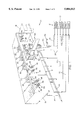
- FIG. 1 is a schematic view of a beverage dispenser in accordance with the present invention not showing elements not relevant to the present invention
- FIG. 2 is a cross-section of the adapter block of the present invention as mounted to a beverage dispenser;
- FIG. 3 is a cross-section of the adapter block and a portion of the spigot taken along line 3--3 of FIG. 2;
- FIG. 4 is a perspective view of the adapter block on a mounting plate with the spigot shown in phantom;
- FIG. 5 is a cross-section of the mounting block similar to FIG. 2 but without the other parts;
- FIG. 6 is a front plan view of the mounting block seen in FIG. 5;
- FIG. 7 is a cross-section of the mounting block taken along line 7--7 of FIG. 5.
- Carbonated beverage dispensers generally comprise sources of syrup and soda 12, chillers 14 and beverage dispensing valves 16. Flavoring syrup is generally provided in bag and box reservoirs or metallic canisters which are replaceable when empty and conventional in design. Chillers 14 generally take the form of either a cold plate or a mechanical ice bank type refrigeration unit. Both forms of chillers are well developed, commercially available and described in numerous patents.
- Dispensing valves 16 are also available from a number of sources commercially and described in a number of patents. Soda water is usually provided by means of a carbonator accepting plain water and carbon dioxide and creating carbonated water at the site of dispensing. These structures are conventional and will not be described in detail.
- Quality beverage dispensers share several attributes. Quality beverage dispensers are well insulated. The tubes leading from the chiller 14 to the beverage dispensing valves 16 are normally embedded in a body of insulation which is often foamed in place insulation. This high R value insulation improves the temperature stability of a dispensed beverage. Quality beverage dispensers use syrup and soda delivery tubes terminating in fittings that are accurately positioned. Accurate positioning of the tube end fittings allows for ease of interchange of beverage dispensing valve 16 and also prevents leaks. A face plate 18 or the like is often used to position the ends of syrup delivery tubes 20 and soda delivery tubes 22. The face plate 18 holds the tubes 20, 22 rigidly in place during manufacturing when foamed in place insulation 24 is applied.
- the tube ends are provided with a syrup delivery tube end fitting 26 and a soda delivery tube fitting 28.
- the end fitting are often provided with circumferential recesses 30 which engage apertures 32 in the face plate 18.
- the apertures 32 have circular portions 34 large enough to admit passage of the end fittings 26, 28.
- the apertures 32 also have engagement portions 36 which are somewhat smaller in lateral dimension than the circular portions 34 and snugly engage the recesses 30 precisely positioning the end fittings 26, 28.
- O-rings 38 are positioned in a second circumferential recess in the end fitting. The end fittings with their O-rings 38 are engaged by matching recesses (not shown) in a beverage dispensing valve 16 to provide a leakfree fluid flow connection.
- Face plate 18 stays in place once the beverage dispenser 10 is completed and provides a surface to which beverage dispensing valves 16 may be attached.
- the face plate 18 also provides protection for the body of insulation. Once such a beverage dispenser 10 is manufactured, the tubing runs cannot be modified without destroying the foamed in place insulation 24.
- a water dispensing station 40 in accordance with the present invention is shown in FIG. 1.
- the water dispensing station takes one of the places normally occupied by a carbonated beverage dispensing valve 16. However, the water dispensing station dispenses plain water.
- the water dispensing station comprises an adapter block 42 and a spigot 44.
- Spigot 44 is conventional and available commercially.
- Spigot 44 has a threaded end 46 and a central bore 48.
- the threaded end 46 is attached to a source of water. Water is thereby introduced into the central bore 48.
- a depending lever 50 has a V-shaped lower end 52 which accommodates a glass to be filled. The glass is pressed against the lever 50 which accuates a valve mechanism within the spigot 44 allowing water to flow from an opening in the spigot 44 above the cup (not shown) thus dispensing water.
- the spigot 44 is accommodated in the threaded hole 60 in the adapter block 42.
- the threaded hole 60 has threads corresponding to those on the threaded end 46 of the spigot 44.
- the threads of both are one-half (1/2) inch national pipe thread.
- a washer 62 is accommodated in a shallow recess 64 surrounding the hole 60.
- the adapter block 42 is also provided with a soda inlet 66 and a syrup inlet 68.
- the soda inlet is a blind cylindrical hole in the back of adapter block 42.
- the soda inlet 66 accommodate the soda delivery tube end fitting 28 and cooperates with O-ring 38 to seal the end of the soda delivery tube 22.
- soda water delivered through the soda tube 22 to the water station 40 is stopped in the blind soda inlet 66.
- the syrup inlet 68 accommodates the syrup delivery tube end fittings 26.
- the O-ring 38 seals this joint providing a water-tight connection.
- the syrup inlet 68 however is not blind. Rather, as seen in FIGS. 3 and 5, it communicates with the threaded hole 60 allowing delivery of fluid to the spigot central bore 48.
- the adapter block 42 is fixed to the face plate 18 by means of four machine screws 70.
- the adapter block 42 is formed from a dimensionally stable material such as Delrin plastic. While a metal block could be used, Delrin plastic is easily formed into the finished shape needed and provides sufficient strength. Screw holes 72 in the adapter block 42 are positioned so that the machine screws 70 mate with tapped hole 74 in the face plate 18. These holes 74 in the face plate 18 are standardized to accept mounting screws for standardized dispensing valve 16.
- one of the syrup delivery tubes 20 is not connected to a source of syrup. Rather, the tube 20a in the syrup tube position leading to the water station 40 is connected to a source of water 80 such as the city water delivery pipe. In this way, water from the source of water 80 is passed through the chiller 14, delivered to the adapter block 42 and provided to the spigot 44 for dispensing into a glass or cup.
- a chilled water dispenser is thereby provided in a carbonated beverage dispensing apparatus.
- the chilled water is provided without the need to modify the internal workings of the beverage dispenser 10. Rather, the only changes necessary are at the face plate 18 and at the source of syrup 12. Changes at these locations are relatively easy.
- the adapter block 42 and spigot 44 are easily retrofitted to existing carbonated beverage dispensers by simply removing an existing dispensing valve 16 and substituting the spigot and adapter block therefor. Four machine screws are used to perform the mounting operation and no further sealing steps are needed. A source of water is connected to the syrup tube leading to the water station 40. Installation of the water dispensing station is easily and quickly completed.
Landscapes
- Engineering & Computer Science (AREA)
- Mechanical Engineering (AREA)
- Devices For Dispensing Beverages (AREA)
Abstract
Description
Claims (4)
Priority Applications (1)
| Application Number | Priority Date | Filing Date | Title |
|---|---|---|---|
| US08/794,946 US5884813A (en) | 1997-02-04 | 1997-02-04 | Method and apparatus for dispensing plain water from a postmix carbonated beverage dispenser |
Applications Claiming Priority (1)
| Application Number | Priority Date | Filing Date | Title |
|---|---|---|---|
| US08/794,946 US5884813A (en) | 1997-02-04 | 1997-02-04 | Method and apparatus for dispensing plain water from a postmix carbonated beverage dispenser |
Publications (1)
| Publication Number | Publication Date |
|---|---|
| US5884813A true US5884813A (en) | 1999-03-23 |
Family
ID=25164166
Family Applications (1)
| Application Number | Title | Priority Date | Filing Date |
|---|---|---|---|
| US08/794,946 Expired - Fee Related US5884813A (en) | 1997-02-04 | 1997-02-04 | Method and apparatus for dispensing plain water from a postmix carbonated beverage dispenser |
Country Status (1)
| Country | Link |
|---|---|
| US (1) | US5884813A (en) |
Cited By (28)
| Publication number | Priority date | Publication date | Assignee | Title |
|---|---|---|---|---|
| US6286721B1 (en) * | 1997-12-18 | 2001-09-11 | Enrica Pellegrini | Modular manifold system for post-mix and pre-mix beverages dispensers |
| US6375042B1 (en) * | 1997-08-06 | 2002-04-23 | Valpar Industrial Limited | Beverage distributing unit |
| USD465119S1 (en) | 2001-10-19 | 2002-11-05 | Manitowoc Foodservice Companies, Inc. | Beverage dispenser |
| WO2002094705A1 (en) * | 2001-05-21 | 2002-11-28 | The Coca-Cola Company | Soft drink dispensing machine with modular customer interface unit |
| US6502724B1 (en) * | 2001-10-03 | 2003-01-07 | Harry Kelpach | Beverage dispensing system |
| US20030230108A1 (en) * | 2002-03-16 | 2003-12-18 | Lucas Alan S. | Ice and ice/beverage dispensers |
| US20080054837A1 (en) * | 2006-03-06 | 2008-03-06 | Beavis Russell H | System and method for generating a drive signal |
| US20080073610A1 (en) * | 1997-08-22 | 2008-03-27 | Manning Casey P | Stopcock valve |
| US20090056813A1 (en) * | 2004-05-21 | 2009-03-05 | Pepsico, Inc. | Beverage dispensing system with a head capable of dispensing plural different beverages |
| US20090159612A1 (en) * | 2007-09-06 | 2009-06-25 | Deka Research & Development Corp. | Product dispensing system |
| US20090277516A1 (en) | 2006-03-06 | 2009-11-12 | Felix Winkler | Product Dispensing System |
| US20100005903A1 (en) * | 2007-09-06 | 2010-01-14 | Deka Products Limited Partnership | Product Dispensing System |
| US20110290336A1 (en) * | 2010-05-25 | 2011-12-01 | Steven Wayne Campbell | Flush Unit For a Fountain Dispenser |
| US20120048887A1 (en) * | 2008-05-27 | 2012-03-01 | Lancer Partnership, Ltd. | Method and apparatus for a beverage dispenser |
| US20140034675A1 (en) * | 2012-08-01 | 2014-02-06 | Schroeder Industries, Inc. D/B/A Schroeder America | Multi-flavor mechanical dispensing valve for a single flavor multi-head beverage dispenser |
| US20140263407A1 (en) * | 2013-03-14 | 2014-09-18 | The Coca-Cola Company | Water Distribution System for a Beverage Dispenser |
| US20160222332A1 (en) * | 2015-01-30 | 2016-08-04 | Anheuser-Busch Inbev S.A. | Methods, appliances, and systems for preparing a beverage from a base liquid and an ingredient |
| US11135345B2 (en) | 2017-05-10 | 2021-10-05 | Fresenius Medical Care Holdings, Inc. | On demand dialysate mixing using concentrates |
| US11208314B2 (en) | 2015-01-30 | 2021-12-28 | Anheuser-Busch Inbev S.A. | Pressurized beverage concentrates and appliances and methods for producing beverages therefrom |
| US11427462B2 (en) | 2007-09-06 | 2022-08-30 | Deka Products Limited Partnership | Product dispensing system |
| US11504458B2 (en) | 2018-10-17 | 2022-11-22 | Fresenius Medical Care Holdings, Inc. | Ultrasonic authentication for dialysis |
| US11634311B2 (en) | 2007-09-06 | 2023-04-25 | Deka Products Limited Partnership | Product dispensing system |
| WO2023066905A1 (en) * | 2021-10-21 | 2023-04-27 | Micro Matic A/S | Beverage tapping column with removable tap and shell |
| US11655806B2 (en) | 2007-09-06 | 2023-05-23 | Deka Products Limited Partnership | Product dispensing system |
| US11661329B2 (en) | 2006-03-06 | 2023-05-30 | Deka Products Limited Partnership | System and method for generating a drive signal |
| US11906988B2 (en) | 2006-03-06 | 2024-02-20 | Deka Products Limited Partnership | Product dispensing system |
| US12135019B2 (en) | 2007-09-06 | 2024-11-05 | Deka Products Limited Partnership | Product dispensing system |
| WO2025149491A1 (en) * | 2024-01-08 | 2025-07-17 | Heineken Uk Limited | Beverage dispense system |
Citations (8)
| Publication number | Priority date | Publication date | Assignee | Title |
|---|---|---|---|---|
| US4485940A (en) * | 1982-01-28 | 1984-12-04 | The Coca-Cola Company | Diluent valve actuator assembly for beverage dispensers |
| US4592490A (en) * | 1984-02-24 | 1986-06-03 | The Coca-Cola Company | Beverage dispenser system convertable between gravity and pressure |
| US5368198A (en) * | 1992-08-26 | 1994-11-29 | Imi Cornelius Inc. | Beverage dispenser |
| US5392960A (en) * | 1992-11-13 | 1995-02-28 | Wilshire Partners | Postmix beverage dispenser and a method for making a beverage dispenser |
| US5433348A (en) * | 1993-01-14 | 1995-07-18 | Lancer Corporation | Modular dispensing tower |
| US5499744A (en) * | 1994-05-03 | 1996-03-19 | Lancer Corporation | Low profile drink dispenser |
| US5685458A (en) * | 1996-01-04 | 1997-11-11 | The Coca-Cola Company | Dispensing valve quick connect interfaces including a non-carbonated beverage bridge |
| US5715700A (en) * | 1995-06-05 | 1998-02-10 | The Coca-Cola Company | Round drink dispenser |
-
1997
- 1997-02-04 US US08/794,946 patent/US5884813A/en not_active Expired - Fee Related
Patent Citations (8)
| Publication number | Priority date | Publication date | Assignee | Title |
|---|---|---|---|---|
| US4485940A (en) * | 1982-01-28 | 1984-12-04 | The Coca-Cola Company | Diluent valve actuator assembly for beverage dispensers |
| US4592490A (en) * | 1984-02-24 | 1986-06-03 | The Coca-Cola Company | Beverage dispenser system convertable between gravity and pressure |
| US5368198A (en) * | 1992-08-26 | 1994-11-29 | Imi Cornelius Inc. | Beverage dispenser |
| US5392960A (en) * | 1992-11-13 | 1995-02-28 | Wilshire Partners | Postmix beverage dispenser and a method for making a beverage dispenser |
| US5433348A (en) * | 1993-01-14 | 1995-07-18 | Lancer Corporation | Modular dispensing tower |
| US5499744A (en) * | 1994-05-03 | 1996-03-19 | Lancer Corporation | Low profile drink dispenser |
| US5715700A (en) * | 1995-06-05 | 1998-02-10 | The Coca-Cola Company | Round drink dispenser |
| US5685458A (en) * | 1996-01-04 | 1997-11-11 | The Coca-Cola Company | Dispensing valve quick connect interfaces including a non-carbonated beverage bridge |
Cited By (63)
| Publication number | Priority date | Publication date | Assignee | Title |
|---|---|---|---|---|
| US6375042B1 (en) * | 1997-08-06 | 2002-04-23 | Valpar Industrial Limited | Beverage distributing unit |
| US20080073610A1 (en) * | 1997-08-22 | 2008-03-27 | Manning Casey P | Stopcock valve |
| US6286721B1 (en) * | 1997-12-18 | 2001-09-11 | Enrica Pellegrini | Modular manifold system for post-mix and pre-mix beverages dispensers |
| US6547100B2 (en) | 2000-05-01 | 2003-04-15 | The Coca-Cola Company | Soft drink dispensing machine with modular customer interface unit |
| JP2009007073A (en) * | 2001-05-21 | 2009-01-15 | Coca Cola Co:The | Soft drink dispensing machine with modular customer interface unit |
| WO2002094705A1 (en) * | 2001-05-21 | 2002-11-28 | The Coca-Cola Company | Soft drink dispensing machine with modular customer interface unit |
| AU2002308704B2 (en) * | 2001-05-21 | 2007-04-05 | The Coca-Cola Company | Soft drink dispensing machine with modular customer interface unit |
| US6502724B1 (en) * | 2001-10-03 | 2003-01-07 | Harry Kelpach | Beverage dispensing system |
| USD465119S1 (en) | 2001-10-19 | 2002-11-05 | Manitowoc Foodservice Companies, Inc. | Beverage dispenser |
| US20030230108A1 (en) * | 2002-03-16 | 2003-12-18 | Lucas Alan S. | Ice and ice/beverage dispensers |
| US6880358B2 (en) | 2002-03-16 | 2005-04-19 | Manitowoc Foodservice Companies, Inc. | Ice and ice/beverage dispensers |
| US20090056813A1 (en) * | 2004-05-21 | 2009-03-05 | Pepsico, Inc. | Beverage dispensing system with a head capable of dispensing plural different beverages |
| US8113384B2 (en) * | 2004-05-21 | 2012-02-14 | Pepsico, Inc. | Beverage dispensing system with a head capable of dispensing plural different beverages |
| US20090057336A1 (en) * | 2004-05-21 | 2009-03-05 | Pepsico, Inc. | Beverage dispensing system with a head capable of dispensing plural different beverages |
| US20090057343A1 (en) * | 2004-05-21 | 2009-03-05 | Pepsico, Inc. | Beverage dispensing system with a head capable of dispensing plural different beverages |
| US8356730B2 (en) | 2004-05-21 | 2013-01-22 | Pepsico, Inc. | Beverage dispensing system with a head capable of dispensing plural different beverages |
| US8616412B2 (en) | 2004-05-21 | 2013-12-31 | Pepsico, Inc. | Beverage dispensing system with a head capable of dispensing plural different beverages |
| US8590746B2 (en) | 2004-05-21 | 2013-11-26 | Pepsico, Inc. | Beverage dispensing system with a head capable of dispensing plural different beverages |
| US9150401B2 (en) | 2004-05-21 | 2015-10-06 | Pepsico, Inc. | Beverage dispensing system with a head capable of dispensing plural different beverages |
| US8127966B2 (en) | 2004-05-21 | 2012-03-06 | Pepsico, Inc. | Beverage dispensing system with a head capable of dispensing plural different beverages |
| US20110024455A1 (en) * | 2004-05-21 | 2011-02-03 | Pepsico, Inc. | Beverage dispensing system with a head capable of dispensing plural different beverages |
| US10040043B2 (en) | 2004-05-21 | 2018-08-07 | Pepsico, Inc. | Beverage dispensing system with a head capable of dispensing plural different beverages |
| US8123080B2 (en) | 2004-05-21 | 2012-02-28 | Pepsico, Inc. | Beverage dispensing system with a head capable of dispensing plural different beverages |
| US8079495B2 (en) | 2004-05-21 | 2011-12-20 | Pepsico, Inc. | Beverage dispensing system with a head capable of dispensing plural different beverages |
| US20090277516A1 (en) | 2006-03-06 | 2009-11-12 | Felix Winkler | Product Dispensing System |
| US11429120B2 (en) | 2006-03-06 | 2022-08-30 | Deka Products Limited Partnership | Product dispensing system |
| US11661329B2 (en) | 2006-03-06 | 2023-05-30 | Deka Products Limited Partnership | System and method for generating a drive signal |
| US7905373B2 (en) | 2006-03-06 | 2011-03-15 | Deka Products Limited Partnership | System and method for generating a drive signal |
| US11906988B2 (en) | 2006-03-06 | 2024-02-20 | Deka Products Limited Partnership | Product dispensing system |
| US20100206400A2 (en) * | 2006-03-06 | 2010-08-19 | Felix Winkler | Product Dispensing System |
| US11975960B2 (en) | 2006-03-06 | 2024-05-07 | Deka Products Limited Partnership | System and method for generating a drive signal |
| US12545572B2 (en) | 2006-03-06 | 2026-02-10 | Deka Products Limited Partneship | System and method for generating a drive signal |
| US9146564B2 (en) | 2006-03-06 | 2015-09-29 | Deka Products Limited Partnership | Product dispensing system |
| US20080054837A1 (en) * | 2006-03-06 | 2008-03-06 | Beavis Russell H | System and method for generating a drive signal |
| US8322570B2 (en) | 2007-09-06 | 2012-12-04 | Deka Products Limited Partnership | Product dispensing system |
| US11427462B2 (en) | 2007-09-06 | 2022-08-30 | Deka Products Limited Partnership | Product dispensing system |
| US8783513B2 (en) * | 2007-09-06 | 2014-07-22 | Deka Products Limited Partnership | Product dispensing system |
| US20090159612A1 (en) * | 2007-09-06 | 2009-06-25 | Deka Research & Development Corp. | Product dispensing system |
| US12338116B2 (en) | 2007-09-06 | 2025-06-24 | Deka Products Limited Partneship | Product dispensing system |
| US12135019B2 (en) | 2007-09-06 | 2024-11-05 | Deka Products Limited Partnership | Product dispensing system |
| US20100005903A1 (en) * | 2007-09-06 | 2010-01-14 | Deka Products Limited Partnership | Product Dispensing System |
| US20110011888A2 (en) * | 2007-09-06 | 2011-01-20 | Russell Beavis | Product dispensing system |
| US11738989B2 (en) | 2007-09-06 | 2023-08-29 | Deka Products Limited Partnership | Product dispensing system |
| US11655806B2 (en) | 2007-09-06 | 2023-05-23 | Deka Products Limited Partnership | Product dispensing system |
| US11634311B2 (en) | 2007-09-06 | 2023-04-25 | Deka Products Limited Partnership | Product dispensing system |
| US8087303B2 (en) | 2007-09-06 | 2012-01-03 | Deka Products Limited Partnership | Product dispensing system |
| US11365107B2 (en) | 2007-09-06 | 2022-06-21 | Deka Products Limited Partnership | Product dispensing system |
| US20120048887A1 (en) * | 2008-05-27 | 2012-03-01 | Lancer Partnership, Ltd. | Method and apparatus for a beverage dispenser |
| US8251259B2 (en) * | 2008-05-27 | 2012-08-28 | Lancer Partnership, Ltd | Method and apparatus for a beverage dispenser |
| US12372987B2 (en) | 2009-05-07 | 2025-07-29 | Deka Products Limited Partnership | Product dispensing system |
| US20110290336A1 (en) * | 2010-05-25 | 2011-12-01 | Steven Wayne Campbell | Flush Unit For a Fountain Dispenser |
| US8534498B2 (en) * | 2010-05-25 | 2013-09-17 | Steven Wayne Campbell | Flush unit for a fountain dispenser |
| US20140034675A1 (en) * | 2012-08-01 | 2014-02-06 | Schroeder Industries, Inc. D/B/A Schroeder America | Multi-flavor mechanical dispensing valve for a single flavor multi-head beverage dispenser |
| US9085451B2 (en) * | 2012-08-01 | 2015-07-21 | Schroeder Industries, Inc. | Multi-flavor mechanical dispensing valve for a single flavor multi-head beverage dispenser |
| US10426290B2 (en) * | 2013-03-14 | 2019-10-01 | The Coca-Cola Company | Water distribution system for a beverage dispenser |
| US20140263407A1 (en) * | 2013-03-14 | 2014-09-18 | The Coca-Cola Company | Water Distribution System for a Beverage Dispenser |
| US11208314B2 (en) | 2015-01-30 | 2021-12-28 | Anheuser-Busch Inbev S.A. | Pressurized beverage concentrates and appliances and methods for producing beverages therefrom |
| US20160222332A1 (en) * | 2015-01-30 | 2016-08-04 | Anheuser-Busch Inbev S.A. | Methods, appliances, and systems for preparing a beverage from a base liquid and an ingredient |
| US11752246B2 (en) | 2017-05-10 | 2023-09-12 | Fresenius Medical Care Holdings, Inc. | On demand dialysate mixing using concentrates |
| US11135345B2 (en) | 2017-05-10 | 2021-10-05 | Fresenius Medical Care Holdings, Inc. | On demand dialysate mixing using concentrates |
| US11504458B2 (en) | 2018-10-17 | 2022-11-22 | Fresenius Medical Care Holdings, Inc. | Ultrasonic authentication for dialysis |
| WO2023066905A1 (en) * | 2021-10-21 | 2023-04-27 | Micro Matic A/S | Beverage tapping column with removable tap and shell |
| WO2025149491A1 (en) * | 2024-01-08 | 2025-07-17 | Heineken Uk Limited | Beverage dispense system |
Similar Documents
| Publication | Publication Date | Title |
|---|---|---|
| US5884813A (en) | Method and apparatus for dispensing plain water from a postmix carbonated beverage dispenser | |
| US4781309A (en) | Dispenser with improved carbonated water manifold | |
| US5310088A (en) | Bottled water station for dispensing carbonated and uncarbonated water | |
| US4941593A (en) | Cleaning system for beverage delivery conduits | |
| AU699528B2 (en) | Cylindrical drink dispenser | |
| CA1275984C (en) | Beverage dispenser | |
| US20020084284A1 (en) | Selection manifold for beverage dispenser | |
| EP0250003A1 (en) | Beverage dispenser | |
| US4615466A (en) | Beverage dispenser system convertable between gravity and pressure | |
| US4592490A (en) | Beverage dispenser system convertable between gravity and pressure | |
| US20090302059A1 (en) | Methods and apparatus for pumping and dispensing | |
| JP5690590B2 (en) | Method and apparatus using conversion valve | |
| US6273295B1 (en) | Water tank and pump system | |
| US5881922A (en) | Coupler switchable among multiple apertures | |
| CA2621746C (en) | Multiple flow circuits for a beverage dispenser | |
| EP0676730A1 (en) | Drink dispenser | |
| US2498524A (en) | Drink vending machine | |
| US20060071015A1 (en) | Water changeover manifold for beverage dispenser and method | |
| US20030183652A1 (en) | Dual diluent post-mix beverage dispenser | |
| US5722567A (en) | Premix beverage dispenser | |
| US6981615B2 (en) | Modular diluent changeover manifold for beverage dispensers | |
| US6161819A (en) | Carbonator cartridge unit for a beverage dispenser system | |
| CN1305433A (en) | A cold drink dispenser | |
| US3277921A (en) | Mixing and dispensing valve | |
| WO1990011961A2 (en) | A multi-flavour drink dispenser |
Legal Events
| Date | Code | Title | Description |
|---|---|---|---|
| AS | Assignment |
Owner name: WILSHIRE PARTNERS, OHIO Free format text: ASSIGNMENT OF ASSIGNORS INTEREST;ASSIGNORS:BORDONARO, ROBERT J.;STEWART, DAVID C.;REEL/FRAME:008453/0714 Effective date: 19970116 |
|
| AS | Assignment |
Owner name: IMI CORNELIUS INC., MINNESOTA Free format text: ASSIGNMENT OF ASSIGNORS INTEREST;ASSIGNOR:IMI WILSHIRE INC.;REEL/FRAME:011177/0043 Effective date: 20000630 |
|
| FPAY | Fee payment |
Year of fee payment: 4 |
|
| REMI | Maintenance fee reminder mailed | ||
| LAPS | Lapse for failure to pay maintenance fees | ||
| STCH | Information on status: patent discontinuation |
Free format text: PATENT EXPIRED DUE TO NONPAYMENT OF MAINTENANCE FEES UNDER 37 CFR 1.362 |
|
| FP | Lapsed due to failure to pay maintenance fee |
Effective date: 20070328 |