US588103A - And james frank duryea - Google Patents
And james frank duryea Download PDFInfo
- Publication number
- US588103A US588103A US588103DA US588103A US 588103 A US588103 A US 588103A US 588103D A US588103D A US 588103DA US 588103 A US588103 A US 588103A
- Authority
- US
- United States
- Prior art keywords
- pipe
- tank
- water
- motor
- cylinders
- Prior art date
- Legal status (The legal status is an assumption and is not a legal conclusion. Google has not performed a legal analysis and makes no representation as to the accuracy of the status listed.)
- Expired - Lifetime
Links
Images

Classifications
-
- B—PERFORMING OPERATIONS; TRANSPORTING
- B60—VEHICLES IN GENERAL
- B60K—ARRANGEMENT OR MOUNTING OF PROPULSION UNITS OR OF TRANSMISSIONS IN VEHICLES; ARRANGEMENT OR MOUNTING OF PLURAL DIVERSE PRIME-MOVERS IN VEHICLES; AUXILIARY DRIVES FOR VEHICLES; INSTRUMENTATION OR DASHBOARDS FOR VEHICLES; ARRANGEMENTS IN CONNECTION WITH COOLING, AIR INTAKE, GAS EXHAUST OR FUEL SUPPLY OF PROPULSION UNITS IN VEHICLES
- B60K11/00—Arrangement in connection with cooling of propulsion units
- B60K11/02—Arrangement in connection with cooling of propulsion units with liquid cooling
- B60K11/04—Arrangement or mounting of radiators, radiator shutters, or radiator blinds
Definitions
- This invention relates to improvements in motor-carriages, and more particularly to the muftling devices connected to theexhaustport of the motor, to improvements in the construction of the water-tank, and means for dissipating the vapors from said water-tank;
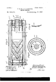
- Figure 1 is a side elevation, partly in section, of a motor-carriage containing the invention.
- 'Figi 2 is a sectional view of a trapped drip-cup and connections.
- Fig. 3 is a longitudinal section of a muliler connected 2 5 with the exhaust-port of the motor.
- Fig. 4 is a cross-section of the same on line 4 4, Fig. 3.
- Fig. 5 is a section through one of the plates of the muflier.
- Fig. G Ais a sectional view of the water-tank and cylinders of the o engine and water-jackets therefor, showing a modied construction of the pipe connections between said tank and jackets.
- A represents the body of the motor-carriage 3 B, the seat there- 3 5 of, having the water tank C, incidentally forming the back of said seat.
- D is the body of the wagon or carriage, containing the motor or engine E.
- a pipe -5 enters the water-tankC through the bottom thereof and is of such length that its upper extremity is near the top of the chamber in said tank and always above the surface of the water therein, (indicated by G.)
- Two pipes 7 and S also enter the said water- 4tank C through the bottom thereof for con- 5o veyin g the water to and from the water-jack- YEA, residing at Springfield, in the county of ets surrounding the cylindersof the motor in the usual manner.
- Said pipe connections, if v desired, may be constructed, as shownin Fig.
- the said pipe 5 is connected by its lower extremity to the trapped drip-cup 9.
- Said drip-cup is of a well-known construction, being cast usually with a cylindrical body and having the diaphragm 10 cast integral with the upper part thereof and extending downwardly therefrom to a point below the overflow 12.
- a plug 13 in the bottom of said cup is provided for the purpose of cleaning it out when desired.
- An outlet 14 pro- 65 jects from the upper part of said drip-cup, preferably curved, as shown in the drawings, for connecting thereto in a horizontal position an outlet-pipe 15.
- Pipe 3 is of such diameter that when the pipe 15 is located therein, as stated, there will be vleft a space 17 between the outer surface of said pipe and the inner surface of ⁇ the pipe 3, the area ofwhich space is considerably larger than the area of said pipe 15.
- the muffler 4 is preferably secured to the end of the pipe 3a, as shown in' Fig. 3 of the drawings-viz., by being screwed thereon.
- the water-tank C forms practically4 the back of the seat and is located in that position not only to economize space, but in order to exposethe sides Vof said tank having thegreatest area to the air. To that end an 9o air-space 1S is provided between the support of the upholstered back of the seat and the side of said tank.
- Said air-space opens into the body ofthe wagon, which is open at the bottom thereof, and air may freely circulate through the space 1S between the side of said tank C and the back of said seat and'aid materially to keep down the temperature of the water in said tank, which in time becomes more or less heated by constantly eirrco culatin g through the water-jackets surrounding the cylinders of the motor, from which it is conveyed to and from the tank C by the pipes 7 and S, as aforesaid.
- the said muiier et consists of three cylinders 20, 2l, and 22,V said cylinders each having its ends closed by the heads 23, 24, and 25.
- Said cylinders are arranged one within the other (see Figs. 3 and 4) on the same longitudinal axis and secured in their proper relativepositions by the bolts 26 and 27, fixed to the inner side of cylinder 22, and which pass through the heads of all of the cylinders and have the jam-nuts 26a and 27a thereon for securing said cylinders tightly on said bolts and securing said heads to said cylinders.
- said heads 23, 24, and 25, at one end of said cylinders are perforated to receive the end of the pipe 3, only one, 23, of said heads being shown screwthreaded for screwing onto the end of said P1P@- Y
- cones 28, 29, and 30, preferably made of perforated sheet metal are arranged equidistant from each other within the cylinder 22, being secured to the inner Walls of said cylinder in any suitable manner with their bases opening toward the open end of the pipe 3a.
- the sides of the cylinder 22 are perforated for a certain distancefrom one end thereof, as shown at 31, and-the opposite end of the cylinder 2l is similarly perforated, as shown at 32, and the end of cylinder 2O is perforated at its end which is oppositely located to the perforatedend 32 of cylinder 21, and said perforations of cylinder 20 are indicated by 33.
- the gases of the exhaust and any Vapor it may have mixed therewith are first separated into line streams by passing through the perforated cones 28, 29, and 30, and then through the perforations 3l of cylinder 22 back to the other end of the second cylinder 2l. Passing through the perforations 32 thereof it again changes its course, and passing to the opposite end of the cylinder 2O it can finally escape into the open air through the perforations 33 of said cylinder.
- the muffler is much more eective ifi lsuppressing all noise arising from the escape of the gases of the exhaust through the perforated partitions through which they pass ⁇ it' the said perforations are made, as shown in IOO Fig. 5-viz., from the inside to the outsidewithV a sharp-tapered instrument, which will make a tapered hole in the metal with a bur projecting more or less from the outside of the sheet of metal; If the holes are iliade by punching out a circular disk, Which is the method which has heretofore been employed, it is necessary to more frequently interrupt the vcurrent of the exhaust, in order to do away with all noise, than is necessary when the perforations are made as shown in Fig. 5.
- a seat providedV with a back wall, a water-tank fixed in proximity to said back wall thereby providing a clear air-space between said wall and tank, pipes, as 7 and S, connecting said tank with the water-jackets of a motor for said vehicle, and a vapor-escape pipe, as 5, one extremity of which communicates with the upper part of said tank-chamber, and having its opposite end extending downwardly through the bottom of said tank, substantially as described.
- a motolga muling device connected to the exhaust-port of said motor, a trapped drip-cup, a Water-tank having a chamber in the upper part thereof, a'
- said muftiin g device consisting of several cylinders of varying diameters having closed ends, said several cylinders being contained one Within another, several hollow cones having coneshaped perforations therethrough secured to the interior of the innermost of said cylinders and in axial alinement therewith, and a series of cone-shaped perforations through the sides of said cylinders alternately disposed as regards the ends thereof whereby the gases passing through said muiing device ,are caused to follow a zigzag course, substantially as described.
Landscapes
- Engineering & Computer Science (AREA)
- Chemical & Material Sciences (AREA)
- Combustion & Propulsion (AREA)
- Transportation (AREA)
- Mechanical Engineering (AREA)
- Exhaust Gas After Treatment (AREA)
Description
(No Model.) -2 Sheets-Sheet 1. C. E. 8; J. P. DURYEA.
MOTOR VEHICLE.
NO- 588,103-- l Patented Aug. 10,1897.
/II/l1l1111111l14 (No Model.) 2 Sheets-Sheet 2.
C. E. 8u J. F. DURYBA.
MOTR VEHICLE.
No. 588,103. Patented Aug. 10,1897.
wvz aga.
nu; scams Ferias cu. Haro-uvm. num-Jon. o, c.
UNITED STATES PATENT OFFICE. A
CHARLES E. DURYEA, OF PEORIA, ILLINOIS, AND JAMES FRANK-DURYEA, OF SPRINGFIELD, MASSACHUSETTS, ASSIGNORS TO THE DURYEA MOTOR VAGON COMPANY, OF SPRINGFIELD, MASSACHUSETTS.
MOTOR-VEHICLE.
SPECIFICATION forming part of Letters Patent No. 588,103, dated August 10, 189'?.
Application iiled November 7, 1896. Serial No. 611,335. (No model.) i i To @ZZ zal/'wm t may concern:
Be it known that we, CHARLES E. DURYEA, residing at Peoria, in the county of Peoria and State of Illinois, and JAMES FRANK DUR- Hampden and State of Massachusetts, citi zens of the United States, have invented new and useful Improvements in Motor-Vehicles, of which the following is a specification.
1o This invention relates to improvements in motor-carriages, and more particularly to the muftling devices connected to theexhaustport of the motor, to improvements in the construction of the water-tank, and means for dissipating the vapors from said water-tank;
and the invention consists in the construction and arrangement of the various devices, all as hereinafter set forth and claimed.
In the drawings forming part of this specizo iication, Figure 1 is a side elevation, partly in section, of a motor-carriage containing the invention. 'Figi 2 is a sectional view of a trapped drip-cup and connections. Fig. 3 is a longitudinal section of a muliler connected 2 5 with the exhaust-port of the motor. Fig. 4 is a cross-section of the same on line 4 4, Fig. 3. Fig. 5 is a section through one of the plates of the muflier. Fig. G Ais a sectional view of the water-tank and cylinders of the o engine and water-jackets therefor, showing a modied construction of the pipe connections between said tank and jackets.
Referring to the drawings, A represents the body of the motor-carriage 3 B, the seat there- 3 5 of, having the water tank C, incidentally forming the back of said seat.
D is the body of the wagon or carriage, containing the motor or engine E.
Secured to the exhaust-port 2 of the motor 4o E by the pipes 3 3 and supported thereby is the muffler 4, which preferably lies in the horizontal position shown in the drawings, Fig. 4. A pipe -5 enters the water-tankC through the bottom thereof and is of such length that its upper extremity is near the top of the chamber in said tank and always above the surface of the water therein, (indicated by G.) Two pipes 7 and S also enter the said water- 4tank C through the bottom thereof for con- 5o veyin g the water to and from the water-jack- YEA, residing at Springfield, in the county of ets surrounding the cylindersof the motor in the usual manner. Said pipe connections, if v desired, may be constructed, as shownin Fig.
6, of pipes of two diameters, one within the other, whereby greater compactness is obtained.V The said pipe 5 is connected by its lower extremity to the trapped drip-cup 9. Said drip-cup is of a well-known construction, being cast usually with a cylindrical body and having the diaphragm 10 cast integral with the upper part thereof and extending downwardly therefrom to a point below the overflow 12. A plug 13 in the bottom of said cup is provided for the purpose of cleaning it out when desired.- An outlet 14 pro- 65 jects from the upper part of said drip-cup, preferably curved, as shown in the drawings, for connecting thereto in a horizontal position an outlet-pipe 15.
The pipes-3 5, supporting the muffler 4, as 7o above stated, are connected by the T 16, as shown in the drawings, and said outlet-pipe 15 enters centrally through one end thereof and extends into said pipe 3a for a certain distance beyond the end of the pipe 3, entering the top of said T. Pipe 3 is of such diameter that when the pipe 15 is located therein, as stated, there will be vleft a space 17 between the outer surface of said pipe and the inner surface of` the pipe 3, the area ofwhich space is considerably larger than the area of said pipe 15.
The muffler 4 is preferably secured to the end of the pipe 3a, as shown in' Fig. 3 of the drawings-viz., by being screwed thereon.
The water-tank C forms practically4 the back of the seat and is located in that position not only to economize space, but in order to exposethe sides Vof said tank having thegreatest area to the air. To that end an 9o air-space 1S is provided between the support of the upholstered back of the seat and the side of said tank. Said air-space opens into the body ofthe wagon, which is open at the bottom thereof, and air may freely circulate through the space 1S between the side of said tank C and the back of said seat and'aid materially to keep down the temperature of the water in said tank, which in time becomes more or less heated by constantly eirrco culatin g through the water-jackets surrounding the cylinders of the motor, from which it is conveyed to and from the tank C by the pipes 7 and S, as aforesaid.
When the water in the tank C becomes heated, any vapor therefrom passes out of said tank through pipe 5 and heretofore has been allowed to escape into the open air, which has been an objection, as many horses are frightened by the sight of steam even in small quantities. In order to overcome this objection and dissipate the vapor arising from the water in the tank C under circumstances just spoken of, said pipe 5 is connected, as aforesaid, to the trapped drip-cup 9, and said vapor passing therethrough in the direction of the arrow shown in Fig. 2 of the drawings discharges into the pipe 3a of the mufder t through the pipe l5, which is connected with said trapped drip-cup. Any of the water of condensation Which forms in the pipes leading to or from said trapped dripcup flows down into said cup and out of it through the outlet-overflow l2. The absolute removal of said vapor is assured by the construction of the inlet to the muffler through the pipes 3a and l5 from said drip-cup. The pipe 3, carrying the exhaust, being of larger area than the pipe l5, carrying the vapor, and the exhaust moving more rapidly through pipe 3a than said vapor moves through pipe 15 and said pipe 15 terminating inside of the pipe 3, the passing of the exhaust through said pipe produces a suction action through pipe l5 on the Well-known principle of similar constructions, as injectors, &c., and consequently any vapor forming in the space in vthe top of the said tank above the Water Will be instantly drawn o and discharged into the muffler 4 and mixed with the hot gases of the exhaust from the cylinders of the engine. The said muiier et consists of three cylinders 20, 2l, and 22,V said cylinders each having its ends closed by the heads 23, 24, and 25. Said cylinders are arranged one within the other (see Figs. 3 and 4) on the same longitudinal axis and secured in their proper relativepositions by the bolts 26 and 27, fixed to the inner side of cylinder 22, and which pass through the heads of all of the cylinders and have the jam-nuts 26a and 27a thereon for securing said cylinders tightly on said bolts and securing said heads to said cylinders. As aforesaid, said heads 23, 24, and 25, at one end of said cylinders, are perforated to receive the end of the pipe 3, only one, 23, of said heads being shown screwthreaded for screwing onto the end of said P1P@- Y Several cones 28, 29, and 30, preferably made of perforated sheet metal, are arranged equidistant from each other within the cylinder 22, being secured to the inner Walls of said cylinder in any suitable manner with their bases opening toward the open end of the pipe 3a.
The sides of the cylinder 22 are perforated for a certain distancefrom one end thereof, as shown at 31, and-the opposite end of the cylinder 2l is similarly perforated, as shown at 32, and the end of cylinder 2O is perforated at its end which is oppositely located to the perforatedend 32 of cylinder 21, and said perforations of cylinder 20 are indicated by 33. By reason of the said oppositely-located perforated ends of said cylinders and the said cones within one of them the gases of the exhaust and any Vapor it may have mixed therewith are first separated into line streams by passing through the perforated cones 28, 29, and 30, and then through the perforations 3l of cylinder 22 back to the other end of the second cylinder 2l. Passing through the perforations 32 thereof it again changes its course, and passing to the opposite end of the cylinder 2O it can finally escape into the open air through the perforations 33 of said cylinder.
The constant interruptions offered to the free passage of the exhaust gases and vapor from the water-tank C by the perforated cones and perforated heads, as described, completely mix the two and dissipate the vapor so completely that it is invisible, the rather high temperature of the exhaust-'gases contributing to this end more or less.
It has been demonstrated in practice that the muffler is much more eective ifi lsuppressing all noise arising from the escape of the gases of the exhaust through the perforated partitions through which they pass `it' the said perforations are made, as shown in IOO Fig. 5-viz., from the inside to the outsidewithV a sharp-tapered instrument, which will make a tapered hole in the metal with a bur projecting more or less from the outside of the sheet of metal; If the holes are iliade by punching out a circular disk, Which is the method which has heretofore been employed, it is necessary to more frequently interrupt the vcurrent of the exhaust, in order to do away with all noise, than is necessary when the perforations are made as shown in Fig. 5.
W'e are aware that exhaust-muftling devices provided With perforated diaphragnis are old, and such a construction is not broadly claimed.v
Having thus described our invention, what we claim, and desire to secure by Letters Patent, is
l. In a motor-vehicle, a seat providedV with a back wall, a water-tank fixed in proximity to said back wall thereby providing a clear air-space between said wall and tank, pipes, as 7 and S, connecting said tank with the water-jackets of a motor for said vehicle, and a vapor-escape pipe, as 5, one extremity of which communicates with the upper part of said tank-chamber, and having its opposite end extending downwardly through the bottom of said tank, substantially as described.
2. In a motor-vehicle, a motolga muling device connected to the exhaust-port of said motor, a trapped drip-cup, a Water-tank having a chamber in the upper part thereof, a'
' pipe connection from said chamber to said muftiin g device consisting of several cylinders of varying diameters having closed ends, said several cylinders being contained one Within another, several hollow cones having coneshaped perforations therethrough secured to the interior of the innermost of said cylinders and in axial alinement therewith, and a series of cone-shaped perforations through the sides of said cylinders alternately disposed as regards the ends thereof whereby the gases passing through said muiing device ,are caused to follow a zigzag course, substantially as described.
CHARLES E. DURYEA. JAMES FRANK DURYEA.
lVitnesses:
WM. H. CHAPIN, R. S. DURYEA.
Publications (1)
| Publication Number | Publication Date |
|---|---|
| US588103A true US588103A (en) | 1897-08-10 |
Family
ID=2656770
Family Applications (1)
| Application Number | Title | Priority Date | Filing Date |
|---|---|---|---|
| US588103D Expired - Lifetime US588103A (en) | And james frank duryea |
Country Status (1)
| Country | Link |
|---|---|
| US (1) | US588103A (en) |
-
0
- US US588103D patent/US588103A/en not_active Expired - Lifetime
Similar Documents
| Publication | Publication Date | Title |
|---|---|---|
| US428307A (en) | Steam-muffler | |
| US557109A (en) | David cociirane | |
| US753845A (en) | Gasolene-engine muffler. | |
| US1339609A (en) | Dust-collector for carbureters | |
| US582485A (en) | reeves | |
| US794226A (en) | Muffler. | |
| US734749A (en) | Noise-muffler. | |
| US1061272A (en) | Engine-muffler. | |
| US956785A (en) | Muffler. | |
| US734878A (en) | Muffler. | |
| US1684186A (en) | Combined muffler and heater | |
| US752994A (en) | mokee | |
| US1162064A (en) | Exhaust-silencer for use in connection with internal-combustion engines. | |
| US514438A (en) | Tkk nattorat | |
| US458299A (en) | Steam-kettle | |
| US791773A (en) | Exhaust-head. | |
| US491482A (en) | Combined steam-muffler and heating apparatus | |
| US1182098A (en) | Silencer. | |
| US331917A (en) | Feed-water purifier | |
| US1515463A (en) | Muffler | |
| US1096970A (en) | Muffler. | |
| US147013A (en) | Improvement in feed-water heaters for locomotives | |
| US1222723A (en) | Muffler. | |
| US768627A (en) | Exhaust-head. | |
| US449120A (en) | Steam-muffler |