US587867A - Carbureter - Google Patents
Carbureter Download PDFInfo
- Publication number
- US587867A US587867A US587867DA US587867A US 587867 A US587867 A US 587867A US 587867D A US587867D A US 587867DA US 587867 A US587867 A US 587867A
- Authority
- US
- United States
- Prior art keywords
- carbureter
- strips
- plates
- oil
- air
- Prior art date
- Legal status (The legal status is an assumption and is not a legal conclusion. Google has not performed a legal analysis and makes no representation as to the accuracy of the status listed.)
- Expired - Lifetime
Links
- 239000004215 Carbon black (E152) Substances 0.000 description 7
- 229930195733 hydrocarbon Natural products 0.000 description 7
- 150000002430 hydrocarbons Chemical class 0.000 description 7
- QSHDDOUJBYECFT-UHFFFAOYSA-N mercury Chemical compound [Hg] QSHDDOUJBYECFT-UHFFFAOYSA-N 0.000 description 4
- 229910052753 mercury Inorganic materials 0.000 description 4
- OKTJSMMVPCPJKN-UHFFFAOYSA-N Carbon Chemical compound [C] OKTJSMMVPCPJKN-UHFFFAOYSA-N 0.000 description 3
- 229910052799 carbon Inorganic materials 0.000 description 3
- 238000010276 construction Methods 0.000 description 3
- 230000000875 corresponding effect Effects 0.000 description 3
- 238000007789 sealing Methods 0.000 description 3
- 101100441413 Caenorhabditis elegans cup-15 gene Proteins 0.000 description 2
- XEEYBQQBJWHFJM-UHFFFAOYSA-N Iron Chemical compound [Fe] XEEYBQQBJWHFJM-UHFFFAOYSA-N 0.000 description 2
- 239000012530 fluid Substances 0.000 description 2
- 229910001369 Brass Inorganic materials 0.000 description 1
- RYGMFSIKBFXOCR-UHFFFAOYSA-N Copper Chemical compound [Cu] RYGMFSIKBFXOCR-UHFFFAOYSA-N 0.000 description 1
- 229910000831 Steel Inorganic materials 0.000 description 1
- 230000006978 adaptation Effects 0.000 description 1
- 239000010951 brass Substances 0.000 description 1
- 229910052802 copper Inorganic materials 0.000 description 1
- 239000010949 copper Substances 0.000 description 1
- 210000004907 gland Anatomy 0.000 description 1
- 239000011521 glass Substances 0.000 description 1
- 230000005484 gravity Effects 0.000 description 1
- 229910052742 iron Inorganic materials 0.000 description 1
- 239000000463 material Substances 0.000 description 1
- 230000001590 oxidative effect Effects 0.000 description 1
- 238000012856 packing Methods 0.000 description 1
- 238000005192 partition Methods 0.000 description 1
- 230000001105 regulatory effect Effects 0.000 description 1
- 230000000284 resting effect Effects 0.000 description 1
- 230000000391 smoking effect Effects 0.000 description 1
- 239000010959 steel Substances 0.000 description 1
- 238000005496 tempering Methods 0.000 description 1
Images

Classifications
-
- F—MECHANICAL ENGINEERING; LIGHTING; HEATING; WEAPONS; BLASTING
- F02—COMBUSTION ENGINES; HOT-GAS OR COMBUSTION-PRODUCT ENGINE PLANTS
- F02M—SUPPLYING COMBUSTION ENGINES IN GENERAL WITH COMBUSTIBLE MIXTURES OR CONSTITUENTS THEREOF
- F02M5/00—Float-controlled apparatus for maintaining a constant fuel level
- F02M5/12—Other details, e.g. floats, valves, setting devices or tools
Definitions
- This invention relates to gasmachines for carbureting air, in which the latter is forced through the hydrocarbon. Vhen the air is permitted to stand in the carbureter and the latter is not in operation, it becomes so enriched that when the gas is firstlighted it smokes, the surplus and unconsumed carbon escaping and settling upon draperies, walls, and otherwise being objectionable, and to obviate this smoking mixers are resorted to for tempering the overcarbureted air.
- the gas is consumed as fast as made, thereby preventing any standing in the carbureter when the latter is resting, and, moreover, the oil or hydrocarbon is supplied to the carbureter in such quantities as used, thereby preventing stratifying of the oil, as happens when the carbureter'is made to answer as a storage-chamber for a bulk of oil.
- a gas of uniform quality and illuminating power is obtained and a steady light is the result.
- a further purpose of the in vention is to secure a distribution of the air to be carbureted over the carbureting-plates, even though the machine should be tip'ped or set'so as to throw the plates out of the horizontal, whereby a thorough enrichingof the air with carbon is attained under all conditions.
- a still further object ofthe invention is to maintain a given level of hydrocarbon in the carbureter, the supply being automatically controlled and regulated according to the consumption of the gas.
- Fig. 5 is a detail view of a carbureting-plate.
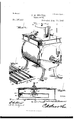
- the machine comprises, essentially, three parts-a carbureter'l, storage-tank 2 for re plenishing the carbu'reter with a hydrocarbon as the latter is consumed, and a pump or blower 3 for forcing a current of air through the carbureter to become laden with carbon on its way to the point of consumption or use.
- the device .3 for generating a current of air may be a fan-blower, pump, or compressor, such as generally used in machines of this character, and is illustrated to show a means for supplying the lair to the carbureter to pr'oduce the gas which is subsequently used for illuminating or other purposes.
- the storage-tank 2 may be of any desired shape and capacity, and is located at a higher level than the carbureter, so that the oil will feed therefrom by gravity.
- a valved vent4 has connection with the top of the tank 2 to prevent theforma-tion of 'a vacuum therein and the escape of gas in the event of the pressure within the tank exceeding the pressure of the surrounding atmosphere. This vent also provides a convenient means of recharging the tank when the latter is nearly eX- hausted or when it is required to refill the same.
- An observation-opening is provided in a side of the tank and is surroundedby a threaded collar 5, which is closedby glass 6 or transparent plate, and which is'heldin place by a ring 7, making screw-threadconnection with the collar 5.
- the opposite end of the collar is protected by a guard 8 of Wire and whose sole purpose is to retain within the IOO collar a buoyant indicator 9, by means of whichthe level of the oil can be readily determined Vhen the level of the oil in the tank is above the observation-opening, the indicator 9 will occupy a position at the top of the opening or collar7 and when the level of the oil falls below the top of the observation-opening the indicator will fall and designate the exact level, provided the latter is within range ot ⁇ the limits of the observationopening, thereby making known when the tank is nearly empty and should be recharged.
- the oil from the tank passes into the carbureter through a pipe 10, trap 11, and nozzle 12, the latter extending into the carbureter and making a tight connection therewith.
- the carbureter comprises a shallow case having a chamber4 13 at one end which contains a proper amount of hydrocarbon to successfully carburet the air.
- Aiioat 14 is placed in the chamber 13 and is provided with-a cup 15, which contains mercury 16 for sealing the discharge end of the nozzle 12 when the chamber'13 is supplied with oil to the predetermined level.
- the cup 15 has an expansionchamber 17 near its upper end, which prevents the loss of the mercury in the event of the carbureter being tipped or suddenly jarred, and this chamber 17 contains a small amount of the hydrocarbon, which prevents the oxidizing of the mercury and maintains the same in condition for 'effective service at all times.
- a series of openings 1S are formed in the sides of the cup above the chamber 17 for the escape of the hydrocarbon into the chamber 13.
- the nozzle 12 works loosely through the upper end of the cup and its lower end is made conical and is adapted to dip into the mercury 16 and is sealed by the latter so as to shut od the supply of oil when the carbureter is properly charged.
- a series of carbureting-plates 19, 20, and 2l are located in the casing and occupy the space formed between the inner wall ot' the chamber 13 andthe opposite wall of the case and extend parallel with the said chamber.
- the plates 19 and 21 extend parallel and inoline slightly throughout their length.
- the middle plate 20 inclines in an opposite direction to the plates 19 and 21 and is secured at one end to a side of the casing and is free at its opposite end, whereas the plates 19 and 21 make a close joint with the case at the ends contiguous to the free end of the plate 20.
- the air is caused to travel in a zigzag or tortuous path through the carbureter, as indicated by the arrows in Fig. 3.
- the plates 19, 20, and 2l are tluted or corrugated in the direction of their len gt-h, and each is provided on its lower side with strips 22 and 23, extending at right angles to the flutes or corrugations and which touch the latter and are secured thereto'at the ridges or crests, thereby providing a series of spaces corresponding to thel position of the channels or grooves.
- the strips 22 are located intermediate the ends of the plates, and the strips 23 are placed series of carburetingplates.
- Strips 24 extend parallel with the corrugations or flutes, and their ends touch the inner sides of the strips 22 and 23.
- Other strips 25 extend vfrom the strips 22 Vto the opposite end of the plates and are arranged to come ⁇ opposite the spaces formed between the strips 24.
- the strips 24 and 25 alternate, the strips 24 coming opposite the spaces formed between the strips 25, and the purpose of this disposition of the strips is to distribute the air over the carbureting-plates in its passage through the carbureter. strips 24 and 25 prevent the oil rushing in a body to one side of the carbureter should the machine from any cause become tipped.
- the air is supplied to the carbureterby i means of a pipe 26 and communicates with mediately below the plate 19, so as to dis' charge the air into the carbureter below the nozzle 29 is located at the opposite end ofthe carbureter and receives the enriched or .carbureted air and directs the same t-o a. discharge-pipe 30, to which the service-pipe in The A gatheringf .95,
- the chamber 13 is divided from u the compartment in which the -carburetingplates are located by means of a partition 31, which latter is formed in its lower edge with a series of notches 32, through which the hyf ⁇ drocarbon .passes from the chamber 13 into the compartment in which the air is carbureted. throughout the upper portion 0f the 'carbu-V In order to equalize the pressure reter, so as to maintain a given level of oil in the chamber 13 and the compartment Vin which the carbureting-plates are looatedfthe inner wall of the part-29 is formed with an opening 33.
- an indice tor consisting of a magnet anda needle is employed, and, as shown, the magnet 34 isnp x15 i i plied to the float 14 and rises and falls Awith the latter, and a needle 35 is located exterior to the case and follows the movementsof they magnet, thereby determining the level'ofthev oil by reference to suitable marks or gradnations provided on the outer side of the case.
- -non-magnetizable material such as Aas copper or brass, be secured in an opening provided opposite to the magnet 34, so that the needle 35 may be attracted by the magnet and follow the movements of the latter.
- the needle may be inthe shapev of a bar or strip and secured to the float and the magnet may be located exterior to the case. This is an obvious construction, but is not nearly as satisfactory as the construction illustrated.
- a carbureter the combination of a float, a cup carried by the iioat and containing a sealing fluid, and having a portion between its ends enlarged to provide a closed expansion-chamber, and having openings in its sides above the expansionrchamber, and a nozzle of smaller diameter than the cup eX- tending therein and closed by the sealing fluid and operating through an opening pro vided in the upper end of the cup, substantially as set forth.
- a gas-machine the combination of a case, a series of carbureting-plates iiuted or corrugated, transverse strips located at one end and intermediate the ends of the plates, and longitudinal strips disposed in parallel relation upon opposite sides of4 the intermediate transverse strips, the strips upon one side of the intermediate transverse strips coming opposite the spaces between theother longitudinal strips, substantially as and for the purpose set forth.
- a case a series of carbureting-plates located therein, a flaring nozzle at one end of the case for distributing the air in iine jets throughout the extent of the carbureting-plates, and a flaring gathering-nozzle at the opposite end of the case for collecting the carbonized air, substantially as set forth.
Landscapes
- Engineering & Computer Science (AREA)
- Chemical & Material Sciences (AREA)
- Combustion & Propulsion (AREA)
- Mechanical Engineering (AREA)
- General Engineering & Computer Science (AREA)
- Separating Particles In Gases By Inertia (AREA)
Description
2 Sheets--Sheet l.
(No Model.)
F. H. SHAVER.
CARBURBTER.
w. 8 n 1, N M g 1 M W d 4 1 /O .mnu Z n 4 D.. n llwllilll .IHHLMNII |mNn w M 6 76 Z M m ww z 7. n a ORM 1 AT h/W., 7, T n w s .QM ...H\ MM|\ M mi wams persas cg mmaumm Mmmm-LN. n cv UNITED STATES PATENT EEICE.
FREDERICK H. SHAVER, Ol? CEDAR RAPIDS, IOWA.
C-ARBURETER.
SPECIFICATION forming part of Letters Patent No. 587,867, dated August 10, 1897.
Application filed J'une 20, 1896. Serial No. 596,334. (No model.)
To all whom it may con/cern:
Beit known that I, FREDERICK H. SHAVER,
. tion.
This invention relates to gasmachines for carbureting air, in which the latter is forced through the hydrocarbon. Vhen the air is permitted to stand in the carbureter and the latter is not in operation, it becomes so enriched that when the gas is firstlighted it smokes, the surplus and unconsumed carbon escaping and settling upon draperies, walls, and otherwise being objectionable, and to obviate this smoking mixers are resorted to for tempering the overcarbureted air.
By this invention the gas is consumed as fast as made, thereby preventing any standing in the carbureter when the latter is resting, and, moreover, the oil or hydrocarbon is supplied to the carbureter in such quantities as used, thereby preventing stratifying of the oil, as happens when the carbureter'is made to answer as a storage-chamber for a bulk of oil. Hence a gas of uniform quality and illuminating power is obtained and a steady light is the result. l Y
A further purpose of the in vention is to secure a distribution of the air to be carbureted over the carbureting-plates, even though the machine should be tip'ped or set'so as to throw the plates out of the horizontal, whereby a thorough enrichingof the air with carbon is attained under all conditions.
A still further object ofthe invention is to maintain a given level of hydrocarbon in the carbureter, the supply being automatically controlled and regulated according to the consumption of the gas.
Other objects and advantages are contemplated and will appear as the nature of the invention is understood; and to this end reference is to be had to the following description and the drawings hereto attached, forming part of this application.
The improvement is susceptible of vario us changes in the form, proportion, and the minor details of construction without departing from the principle or sacrificing any of the advantages thereof, and to a full disclosure of the invention an adaptation thereof is shown in the accompanying drawings, in
` which- X X of Fig. 2, looking in the direction of the arrow. Fig. et is a longitudinal sectionof the carbureter on the -line Y Y of Fig. 2, looking to the left, as indicated by the arrow. Fig. 5 is a detail view of a carbureting-plate.
Corresponding and like parts are referred yto in the following description and indicated in the several views of the accompanying drawings by the saine reference-characters.
The machine comprises, essentially, three parts-a carbureter'l, storage-tank 2 for re plenishing the carbu'reter with a hydrocarbon as the latter is consumed, and a pump or blower 3 for forcing a current of air through the carbureter to become laden with carbon on its way to the point of consumption or use.` The device .3 for generating a current of air may be a fan-blower, pump, or compressor, such as generally used in machines of this character, and is illustrated to show a means for supplying the lair to the carbureter to pr'oduce the gas which is subsequently used for illuminating or other purposes.
The storage-tank 2 may be of any desired shape and capacity, and is located at a higher level than the carbureter, so that the oil will feed therefrom by gravity. A valved vent4 has connection with the top of the tank 2 to prevent theforma-tion of 'a vacuum therein and the escape of gas in the event of the pressure within the tank exceeding the pressure of the surrounding atmosphere. This vent also provides a convenient means of recharging the tank when the latter is nearly eX- hausted or when it is required to refill the same.AY An observation-opening is provided in a side of the tank and is surroundedby a threaded collar 5, which is closedby glass 6 or transparent plate, and which is'heldin place by a ring 7, making screw-threadconnection with the collar 5. The opposite end of the collar is protected by a guard 8 of Wire and whose sole purpose is to retain within the IOO collar a buoyant indicator 9, by means of whichthe level of the oil can be readily determined Vhen the level of the oil in the tank is above the observation-opening, the indicator 9 will occupy a position at the top of the opening or collar7 and when the level of the oil falls below the top of the observation-opening the indicator will fall and designate the exact level, provided the latter is within range ot` the limits of the observationopening, thereby making known when the tank is nearly empty and should be recharged. The oil from the tank passes into the carbureter through a pipe 10, trap 11, and nozzle 12, the latter extending into the carbureter and making a tight connection therewith.
The carbureter comprises a shallow case having a chamber4 13 at one end which contains a proper amount of hydrocarbon to successfully carburet the air. Aiioat 14 is placed in the chamber 13 and is provided with-a cup 15, which contains mercury 16 for sealing the discharge end of the nozzle 12 when the chamber'13 is supplied with oil to the predetermined level. The cup 15 has an expansionchamber 17 near its upper end, which prevents the loss of the mercury in the event of the carbureter being tipped or suddenly jarred, and this chamber 17 contains a small amount of the hydrocarbon, which prevents the oxidizing of the mercury and maintains the same in condition for 'effective service at all times. A series of openings 1S are formed in the sides of the cup above the chamber 17 for the escape of the hydrocarbon into the chamber 13. The nozzle 12 works loosely through the upper end of the cup and its lower end is made conical and is adapted to dip into the mercury 16 and is sealed by the latter so as to shut od the supply of oil when the carbureter is properly charged.
A series of carbureting- plates 19, 20, and 2l are located in the casing and occupy the space formed between the inner wall ot' the chamber 13 andthe opposite wall of the case and extend parallel with the said chamber. The plates 19 and 21 extend parallel and inoline slightly throughout their length. The middle plate 20 inclines in an opposite direction to the plates 19 and 21 and is secured at one end to a side of the casing and is free at its opposite end, whereas the plates 19 and 21 make a close joint with the case at the ends contiguous to the free end of the plate 20. By reason of this disposition of the plates the air is caused to travel in a zigzag or tortuous path through the carbureter, as indicated by the arrows in Fig. 3. The plates 19, 20, and 2l are tluted or corrugated in the direction of their len gt-h, and each is provided on its lower side with strips 22 and 23, extending at right angles to the flutes or corrugations and which touch the latter and are secured thereto'at the ridges or crests, thereby providing a series of spaces corresponding to thel position of the channels or grooves. The strips 22 are located intermediate the ends of the plates, and the strips 23 are placed series of carburetingplates.
at one end. Strips 24 extend parallel with the corrugations or flutes, and their ends touch the inner sides of the strips 22 and 23. Other strips 25 extend vfrom the strips 22 Vto the opposite end of the plates and are arranged to come` opposite the spaces formed between the strips 24. On reference to Fig. 5 it will be seen that the strips 24 and 25 alternate, the strips 24 coming opposite the spaces formed between the strips 25, and the purpose of this disposition of the strips is to distribute the air over the carbureting-plates in its passage through the carbureter. strips 24 and 25 prevent the oil rushing in a body to one side of the carbureter should the machine from any cause become tipped.
Y The air is supplied to the carbureterby i means of a pipe 26 and communicates with mediately below the plate 19, so as to dis' charge the air into the carbureter below the nozzle 29 is located at the opposite end ofthe carbureter and receives the enriched or .carbureted air and directs the same t-o a. discharge-pipe 30, to which the service-pipe in The A gatheringf .95,
connected.- The chamber 13 is divided from u the compartment in which the -carburetingplates are located by means of a partition 31, which latter is formed in its lower edge with a series of notches 32, through which the hyf` drocarbon .passes from the chamber 13 into the compartment in which the air is carbureted. throughout the upper portion 0f the 'carbu-V In order to equalize the pressure reter, so as to maintain a given level of oil in the chamber 13 and the compartment Vin which the carbureting-plates are looatedfthe inner wall of the part-29 is formed with an opening 33.
In order that the level of the oil inthe cam bureter may be indicated without exposing the machine to the danger of fire, an indice tor consisting of a magnet anda needle is employed, and, as shown, the magnet 34 isnp x15 i i plied to the float 14 and rises and falls Awith the latter, and a needle 35 is located exterior to the case and follows the movementsof they magnet, thereby determining the level'ofthev oil by reference to suitable marks or gradnations provided on the outer side of the case.
When the tank is constructed of sheet iron or steel, it is essential to the successful op eration of the indicator that a panel 36,10f
-non-magnetizable material, such Aas copper or brass, be secured in an opening provided opposite to the magnet 34, so that the needle 35 may be attracted by the magnet and follow the movements of the latter.
The position of the magnet and needle may be reversed and the same results be attained:-
that is, the needle may be inthe shapev of a bar or strip and secured to the float and the magnet may be located exterior to the case. This is an obvious construction, but is not nearly as satisfactory as the construction illustrated.
Provision is had for varying the level of the oil in the carbureter, and this is accom.
plished by having the nozzle l2 adjustably connected with the carbureter, packing 37 being interposed between the shoulder of the nozzle and the gland attached to the top of the carbureter, so as' to insure a tight joint to prevent escape ofthe gas.
Having thus described the invention, what is claimed as new isl. In a carbureter, the combination of a float, a cup carried by the iioat and containing a sealing fluid, and having a portion between its ends enlarged to provide a closed expansion-chamber, and having openings in its sides above the expansionrchamber, and a nozzle of smaller diameter than the cup eX- tending therein and closed by the sealing fluid and operating through an opening pro vided in the upper end of the cup, substantially as set forth.
2. In a gas-machine, the combination of a case, a series of carbureting-plates oppositely inclining and having passages at their higher ends, and longitudinal and transverse strips interposed between the plates and correspond-- ing to the space formed between them, the longitudinal strips touching adjacent plates at their upper and lower edges, and the transverse strips having spaces at intervals along their top and bottom edges, substantially as and for the purpose set forth.
3.V In a gas-machine, the combination of a case,a series of superposed carbureting-plates located within the case and oppositely inclining and having spaces at their higher ends,
and longitudinally fluted or corrugated, and transverse strips placed between the plates and touching the crests or ridges of the flutes thereof and providing spaces intermediate of the engaging points, substantially as and for the purpose set forth.
4. In a gas-machine, the combination of a case, a series of carbureting-plates iiuted or corrugated, transverse strips located at one end and intermediate the ends of the plates, and longitudinal strips disposed in parallel relation upon opposite sides of4 the intermediate transverse strips, the strips upon one side of the intermediate transverse strips coming opposite the spaces between theother longitudinal strips, substantially as and for the purpose set forth.
5. In a gas-machine, the combination of a case, a series of carbureting-plates located therein, a flaring nozzle at one end of the case for distributing the air in iine jets throughout the extent of the carbureting-plates, and a flaring gathering-nozzle at the opposite end of the case for collecting the carbonized air, substantially as set forth.
In testimony that I claim the foregoing as my own I have hereto affixed my signature in the presence of two witnesses.
FREDERICK H. SHAVER.
Witnesses:
JOHN H. SreeERs, THEoDoRE DALTON.
Publications (1)
| Publication Number | Publication Date |
|---|---|
| US587867A true US587867A (en) | 1897-08-10 |
Family
ID=2656534
Family Applications (1)
| Application Number | Title | Priority Date | Filing Date |
|---|---|---|---|
| US587867D Expired - Lifetime US587867A (en) | Carbureter |
Country Status (1)
| Country | Link |
|---|---|
| US (1) | US587867A (en) |
-
0
- US US587867D patent/US587867A/en not_active Expired - Lifetime
Similar Documents
| Publication | Publication Date | Title |
|---|---|---|
| US474838A (en) | Carburetor | |
| US355594A (en) | Gottlieb daimler | |
| US765108A (en) | Carbureter. | |
| US887017A (en) | Carbureter. | |
| US775859A (en) | Means for carbureting air. | |
| US475972A (en) | Carburetor | |
| US938011A (en) | Carbureter. | |
| US681382A (en) | Feed-cup for explosive-engines. | |
| US910207A (en) | Carbureter. | |
| US693273A (en) | Carbureter. | |
| US193407A (en) | Improvement in apparatus for manufacturing illuminating-gas | |
| US155096A (en) | Improvement in carbureters | |
| US825336A (en) | Carbureter. | |
| US688931A (en) | Carbureter. | |
| US563799A (en) | Ments | |
| US164558A (en) | Improvement in carbureters | |
| US540536A (en) | Gasoline-gas machine | |
| US395616A (en) | Carburetor | |
| US1914089A (en) | Automatic gasoline vapor generator | |
| US798418A (en) | Carbureter. | |
| US940652A (en) | Carbureter. | |
| US923377A (en) | Carbureter. | |
| US819074A (en) | Gas-generating machine. | |
| US311858A (en) | Gas-machine | |
| US286515A (en) | weston |