US587768A - thielscher - Google Patents
thielscher Download PDFInfo
- Publication number
- US587768A US587768A US587768DA US587768A US 587768 A US587768 A US 587768A US 587768D A US587768D A US 587768DA US 587768 A US587768 A US 587768A
- Authority
- US
- United States
- Prior art keywords
- skate
- sole
- heel
- blade
- levers
- Prior art date
- Legal status (The legal status is an assumption and is not a legal conclusion. Google has not performed a legal analysis and makes no representation as to the accuracy of the status listed.)
- Expired - Lifetime
Links
- 238000010276 construction Methods 0.000 description 7
- 210000003127 knee Anatomy 0.000 description 4
- 206010037660 Pyrexia Diseases 0.000 description 1
- 230000006835 compression Effects 0.000 description 1
- 238000007906 compression Methods 0.000 description 1
- 239000013013 elastic material Substances 0.000 description 1
- 210000003414 extremity Anatomy 0.000 description 1
- 230000000284 resting effect Effects 0.000 description 1
Images


Classifications
-
- A—HUMAN NECESSITIES
- A63—SPORTS; GAMES; AMUSEMENTS
- A63C—SKATES; SKIS; ROLLER SKATES; DESIGN OR LAYOUT OF COURTS, RINKS OR THE LIKE
- A63C1/00—Skates
- A63C1/22—Skates with special foot-plates of the boot
- A63C1/28—Pivotally-mounted plates
Definitions
- Our invention relates to skates; and its novel features consist in the arrangement and construction of the devices for fastening the skate to the shoe, which parts are adapted to work entirely automatically.
- Our improved skate is adapted to be attached to the shoe by merely placing the foot on the sole-plate of the skate and pushing the foot downward.
- our improved skate is provided with means enabling the same to stand upright upon the ice, so that the skater merely places his foot on the skate and pushes downward.
- the skate is also constructed so as to allow of a quick and easy removal from the shoe.
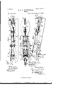
- Figure 1 shows a vertical section, and Fig. 2 a bottom view, of the skate without the blade in the locked position.
- Fig. 3 is a side view of a skate opened and ready to be stepped into.
- Fig. 4 shows a detail of construction.
- Fig. 5 is a vertical and Fig. 6 a horizontal section, and Fig. 7 an elevation,of a skate wherein the locking device is located at the heel of the skate, Fig. 8 being a detail of parts-at the heel.
- Fig. 9 is a vertical and Fig. 10 a horizontal section in locked position of a skate wherein the blade itselfis used as a lockinglcver.
- Fig. 11 is a detail.
- Fig. 12 is a sectional elevation of the parts in the unlocked position, and Fig. 13 a detail of certain parts near the toe of the skate.
- Fig. 14 is a vertical and Fig. 15 a horizontal section of a skate having a somewhat similar arrangement of parts to Fig.
- FIG. 16 is an elevation of the skate in unlocked posit-ion, Fig. 1'7 being a detail of certain parts near the heel of the skate.
- the screw-spindle S carries the nut m, sliding in the groove to of the sole-plate T and bearing the heel-clasp b.
- the square screwhead K slides in the wing-key a, revolving in the heel-support p.
- Said screw-spindle S carries at its other end a cross-head n with double bolts, to which are pivoted on both sides of the blade L the armso of the kneelevers o and r.
- the arms r 'r of the kneelever are pivoted at the front end to the bolt B of the shank of the sole-clasp.
- the pivot-bolt B slides in the ordinary way in the groove a of the sole-plate T, and the shanks ttofthe sole-clasps are also provided with grooves, so as to move about the guidebolts E, fixed to the sole-plate T.
- the spring R securing the flap 'P in its closed position, extends under the sole-plate 1 veniently enter.
- Figs. 5, 6, 7, and 8 represent a skate similar to the construction above described, the only difference being that the locking device is located at the heel end of the skate.
- the free ends of the levers 10 w? are located under the heel part of the skate.
- the groove a in which the pivot-bolt B of the arms 15 t of the sole-clasp slides, is placed more to the middle of the sole-plate '1.
- the arms t t of the sole-claspsand the slots in the same run in a direction toward the forward part of the skate.
- the rests w m are arranged on both sides of the heel-supportsp along the heel-support p, serving as a closing-piece, but on the piece it, fixed under the heel and similar to the head of the above-described closing-piece V, Fig. 4.
- the movement of the locking devices 1 is limited with respect to the levers 10 10 by the pins f f passing over the upper surface of the device. The skate is adjusted in the same manner as described before.
- a skate is represented in which the blade itself is used as a locking-lever, and for this purpose the soleplate and blade are not rigidly connected.
- the construction of the skate is as follows:
- the jointed connection between the sole-plateT and the blade L is obtained by the heel-support 19 which is rigidly attached to the sole-plate T, being pivoted' at s to the blade L. .
- the swinging distance of these pivoted parts attached to each arms r are extended over the knees and bent down outwardly.
- These extens1ons,servmg as supports to the open skate, are indicated in i the accompanying drawings by the letter 10.
- the blade L is connected with the sole-plate T in the manner below described.
- the connecting-piece it consists of'two fiat strips arranged at both sides of the forward support of the sole-plate and provided with slots e, moving about studs 2
- the forward end of the piece a is pivotally connected with the 1 locking device if.
- a hook 00 fastened to the sole-plate T extends in the box and is adapted to hold the end of the piece a.
- the slots A In the side walls of the box V are formed the slots A, in which the studs N of the arms 0 slide.
- the movable connection of the blade L, serving as closinglever, with the knee-levers o r is thus obtained.
- the foremost support of the soleplate has a projection h corresponding with a hole in the sole-plate T.
- the connectingpiece to is normally held in the box V by means of a spiral spring F.
- the skate finds a suiiicient basis of support to enable it to stand upright in the sidewisebent supporting-arms 20 10 and the blade.
- To refasten the skate to the shoe it is simply necessary to tread on the sole-plate T.
- the hook 00 enters into the box V, thereby acting upon the obliquely-cut head of the connecting-piece u, which is pushed back.
- the piece a under the action of the spring F, automatically enters into the hook and in such a manner brings about the rigid connection of the sole-plate and the blade.
- the knee-levers 0 7' In closing the skate the knee-levers 0 7' must be extended and the clasps holding the shoe are forced against the same, as described.
- Figs. 14 15, 16, and 17 is represented a skate which is similar to the one above described, but the closing mechanism is here located under the heel part.
- the difference in this skate and the one above described is as follows:
- the sole-plate T and the blade L are connected at the forward end by a pivot 5
- the middle support D consists of two parts, one half, D, being fastened to the blade L and the other half, D, to the sole-plate T.
- the two parts are surrounded by a strong spiral spring M, which holds the supporting halves together and continually forces the sole-plate T and the blade L apart.
- the screw-spindle S lies with its head K under the middle of the sole plate T.
- the skate can in this condition be put on, as sufficient supporting-points exist in the blade L and the arms 10 If the foot be now placed upon the open skate, the sole-plate T is turned downward after a compression of the spiral spring M. The hook x presses on the obliquely-cut head -of the piece a, whereby the latter is pushed back until it can spring into the opening of the eyelet underthe impulse of the spiral spring F.
- the sole-plate T and the blade L the leverarms 0 are raised, together with the leverarms
- the knee-levers 0 r are extended, and thereby the drawing in of the sole and heel clasps to the shoe is effected.
Landscapes
- Footwear And Its Accessory, Manufacturing Method And Apparatuses (AREA)
Description
. 4 Sheets.8heet 2. H.-&' P. THIELSGHER.
SKATE.
Patented Aug. 10, 1897.v
('No MOI-181.)
WLinems es;
v4: Sheets-Sheet 3. I
(No Model.)
H. 8v P. THIELSGHER. I
SKATE.
No. 587,768. Patented Aug. 10,1897.
\ S V .WWWW I na ???22%a, N Q
m: non-us rrrzus w. PMOYo-UTMI. wumnom, a. c.
4 Sheets-Sheet 4.
H. & P. THIELSCHER.
(No Model.)
SKATE.
No. 587,768. r Patented Aug. 10,1897.
w: ncmals FEVERS cu. moumu. wunma'rou n c Wtinzsses;
UNITED STATES PATENT OFFICE.
HERMANN TIIIELSOHER AND PAUL THIELSCHER, OF BRIEG, GERMANY.
SKATE.
SPECIFICATION forming part of Letters Patent No. 587,768, dated August 10, 1897.
Application filed March 10, 1896. Serial No. 582,572. (No model.)
To (oZZ whom it may concern:
Be it known that we,HERMANN THIELSCHER and PAUL THIELSCHER, subjects of the Emperor of Germany, residing at Brieg, near Breslau, Germany,have invented certain new and useful Improvements in Skates, of which the following is a specification.
Our invention relates to skates; and its novel features consist in the arrangement and construction of the devices for fastening the skate to the shoe, which parts are adapted to work entirely automatically.
Our improved skate is adapted to be attached to the shoe by merely placing the foot on the sole-plate of the skate and pushing the foot downward. To this end our improved skate is provided with means enabling the same to stand upright upon the ice, so that the skater merely places his foot on the skate and pushes downward. The skate is also constructed so as to allow of a quick and easy removal from the shoe.
Referring to the drawings which accompany this specification, we have shown our new skate in different constructions, the fundamental principle of the invention, however, being the same in all constructions.
Figure 1 shows a vertical section, and Fig. 2 a bottom view, of the skate without the blade in the locked position. Fig. 3 is a side view of a skate opened and ready to be stepped into. Fig. 4 shows a detail of construction. Fig. 5 is a vertical and Fig. 6 a horizontal section, and Fig. 7 an elevation,of a skate wherein the locking device is located at the heel of the skate, Fig. 8 being a detail of parts-at the heel. Fig. 9 is a vertical and Fig. 10 a horizontal section in locked position of a skate wherein the blade itselfis used as a lockinglcver. Fig. 11 is a detail. Fig. 12 is a sectional elevation of the parts in the unlocked position, and Fig. 13 a detail of certain parts near the toe of the skate. Fig. 14 is a vertical and Fig. 15 a horizontal section of a skate having a somewhat similar arrangement of parts to Fig. land in locked position. Fig.
16 is an elevation of the skate in unlocked posit-ion, Fig. 1'7 being a detail of certain parts near the heel of the skate.
The screw-spindle S carries the nut m, sliding in the groove to of the sole-plate T and bearing the heel-clasp b. The square screwhead K slides in the wing-key a, revolving in the heel-support p. Said screw-spindle S carries at its other end a cross-head n with double bolts, to which are pivoted on both sides of the blade L the armso of the kneelevers o and r. The arms r 'r of the kneelever are pivoted at the front end to the bolt B of the shank of the sole-clasp.
The pivot-bolt B slides in the ordinary way in the groove a of the sole-plate T, and the shanks ttofthe sole-clasps are also provided with grooves, so as to move about the guidebolts E, fixed to the sole-plate T. I
- It is obvious that the sole-clasps will be moved nearer together and the heel-clasp moved backward when the knee of the levers 0 r is forced upward, and that these parts can be moved in an opposite direction when the knee-lever is moved downward. The movementof the knee-levers o ris efiected by means of the levers w w, which are pivoted to the under side of the sole-plate at q q. The arms 0 of the knee-lever are likewise connected with the levers w w by means of the pin N, moving in the slot A.
To the inside of the forward ends of the levers w it, which are made of elastic material, are pivoted the shanks of the locking 80. devices 1 The upper ends of the lockingpieces 3 are securely fastened together by means of a rivet-bolt 2'. The other ends of these devices grasp under the levers w w by means of their outwardly-bent extremities ff for the purpose of lifting these levers out of the supporting-points as :0, which are arranged in the closing-piece V, secured to the sole-plate T. These supporting-points are in the shape of recesses 00 x, the lower part 0 of the piece V being in the form of a head It, as shown. The locking devices 3 lie under this head and sdmewhat open. Then the hook-shaped clasp of the ends of such device is pressed downward, the head 7.: enters between like a wedge and the levers w ware forced apart until they can slide sidewis down the head 76.
To the levers 'w w are connected the arms in, which are pivoted at G and which are se- 10o cured both in a parallel and a perpendicular position by the spring M.
The spring R, securing the flap 'P in its closed position, extends under the sole-plate 1 veniently enter.
T and here rests upon the screw-spindle S. Any possibly backward motion of the screwspindle S, when the skate is open, Fig. 3, and consequently the locking of the skate, is thereby prevented.
hen using the skate, the levers w to must be first locked. The sole-clasps are then drawn apart from each other by the hand so far that the shoe to which the skate is to be fixed can be placed between the clasps. Then by turning the wing-key c the heel-clasp Z) is displaced sufiiciently to allow the heel to con The shoe must now be placed on the sole-plate and the screw-spindle S turned until the heel-clasp abuts against the shoe-heel,whereupon (byfurther turning) the screw-spindle S, together with the crosshead n, the jointed levers r, the pivot-bolt B, and the shanks of the sole-clasps t, sliding along the studs E, are forced forward and the sole-clasps close themselves. WVhen the skate is set tight, the wing-key c is fixed in the ordinary way by means of the elastic flap P, one of the wings of the key being held in a groove provided in said flap.
For removing the skate it is sufficient to push down the hook-shaped part of the lockin g device y, whereby the levers w w are lifted from their rests x w and moved in a downward direction. Hereby the knees of the levers 0 'r are moved downward also, and the skate is opened. To refasten, the arm 10 must be folded downward. The shoe can then be placed thereon, as theskate is sufficiently supported by the said arm and the end of the blade. The open skate is then stepped on, whereby the closing-levers w w are forced in their rests m x, it being understood that the arms w are longer than the height of the blade. As the levers w w are forced upward the jointed levers 0 1', which are connected with the same, are straightened and the clasps firmly pushed against the shoe. Finally the arm w is closed against the foot by sliding forward.
Figs. 5, 6, 7, and 8 represent a skate similar to the construction above described, the only difference being that the locking device is located at the heel end of the skate. In this construction the free ends of the levers 10 w? are located under the heel part of the skate. The groove a, in which the pivot-bolt B of the arms 15 t of the sole-clasp slides, is placed more to the middle of the sole-plate '1. The arms t t of the sole-claspsand the slots in the same run in a direction toward the forward part of the skate. The rests w m are arranged on both sides of the heel-supportsp along the heel-support p, serving as a closing-piece, but on the piece it, fixed under the heel and similar to the head of the above-described closing-piece V, Fig. 4. The movement of the locking devices 1 is limited with respect to the levers 10 10 by the pins f f passing over the upper surface of the device. The skate is adjusted in the same manner as described before.
In Figs. 9,10, 1], l2, and 13 a skate is represented in which the blade itself is used as a locking-lever, and for this purpose the soleplate and blade are not rigidly connected.
The construction of the skate, as shown in the drawings, is as follows: The jointed connection between the sole-plateT and the blade L is obtained by the heel-support 19 which is rigidly attached to the sole-plate T, being pivoted' at s to the blade L. .The swinging distance of these pivoted parts attached to each arms r are extended over the knees and bent down outwardly. These extens1ons,servmg as supports to the open skate, are indicated in i the accompanying drawings by the letter 10. The blade L is connected with the sole-plate T in the manner below described. The connecting-piece it consists of'two fiat strips arranged at both sides of the forward support of the sole-plate and provided with slots e, moving about studs 2 The forward end of the piece a is pivotally connected with the 1 locking device if.
box V, fastened to the blade L and which forms the middle support of the sole-plate T. A hook 00 fastened to the sole-plate T, extends in the box and is adapted to hold the end of the piece a. In the side walls of the box V are formed the slots A, in which the studs N of the arms 0 slide. The movable connection of the blade L, serving as closinglever, with the knee-levers o r is thus obtained. The foremost support of the soleplate has a projection h corresponding with a hole in the sole-plate T. The connectingpiece to is normally held in the box V by means of a spiral spring F. I
The use of this skate is as follows: After the sole and heel clasps have been fastened to the shoe in the same way as in the skatespreviously described the locking device 3 is forced down. The connecting-piece it, under the action of the spiral spring F, is drawn back, and the end of said piece to is drawn out of the hook 02 The blade L is then turned downward at the pivot-bolt .9. Hereby the knee-levers 0 r connecting-with the blade by means of the stud N in the slots A, are likewise forced downward. The joint of The rear end of the con- Y necting-piece is cut obliquely and rests in a i 95 the same is likewise drawn down and thesoleclasps and heel-clasps are removed from the U shoe. The latter can then be removed from the sole-plate.
The skate finds a suiiicient basis of support to enable it to stand upright in the sidewisebent supporting-arms 20 10 and the blade. To refasten the skate to the shoe, it is simply necessary to tread on the sole-plate T. Hereby the hook 00 enters into the box V, thereby acting upon the obliquely-cut head of the connecting-piece u, which is pushed back. When the hook 00 is forced sufficiently far into the box, the piece a, under the action of the spring F, automatically enters into the hook and in such a manner brings about the rigid connection of the sole-plate and the blade. In closing the skate the knee-levers 0 7' must be extended and the clasps holding the shoe are forced against the same, as described.
In Figs. 14:, 15, 16, and 17 is represented a skate which is similar to the one above described, but the closing mechanism is here located under the heel part. The difference in this skate and the one above described is as follows: The sole-plate T and the blade L are connected at the forward end by a pivot 5 The middle support D consists of two parts, one half, D, being fastened to the blade L and the other half, D, to the sole-plate T. The two parts are surrounded by a strong spiral spring M, which holds the supporting halves together and continually forces the sole-plate T and the blade L apart. The screw-spindle S lies with its head K under the middle of the sole plate T. The screw-threaded end, together with the cross-head fitted with double studs, is placed in the direction of the heel. The pivot-bolt B and the arms 29* of the sole-clasps are similarly constructed, as shown in Figs. 5 to 8. The arms of the knee-levers 0 r are extended beyond their knees. These extensions of the'arms o are provided with slots A By these slots the lever-arms o are guided by the bolt N which is placed in the heelsupport 19 In the same manner the connecting-piece u'.is guided by the bolt N which passes through a slot of the piece located in the support 19. The hook so is fixed to the soleplate T above the piece a. The opening of the piece it occurs under the influence of an angular lever 3 pivoted at z to a flap-shaped contrivance of the heel-support p. The lever if acts upon the piece it by means of a slot in the bolt catching the piece. The spiral spring F forces the lever 3 and the piece M, respectively, always into the locking position. The fastening and loosening of the skate are effectedin asimilar manner as is the skate described under Figs. 9 to 13. By movin g the lever g in a downward direction the piece a is drawn, as shown, out of the hook 00*, whereupon the sole-plate T and the blade L are forced apart by the pressure of the spiral spring M and turn around the pivot 8 The skate now opens, as, owing to the parting of the sole-plate T from the blade L next to the heel parts, the lever-arm 0 which is connected with the heel-support p resting on' the blade L, and consequently also the lever-arm 0 and its extensions 20, which are bent downward, are forced downward, whereby the clasps of the skate are separated. The skate can in this condition be put on, as sufficient supporting-points exist in the blade L and the arms 10 If the foot be now placed upon the open skate, the sole-plate T is turned downward after a compression of the spiral spring M. The hook x presses on the obliquely-cut head -of the piece a, whereby the latter is pushed back until it can spring into the opening of the eyelet underthe impulse of the spiral spring F. By the approach of the sole-plate T and the blade L the leverarms 0 are raised, together with the leverarms The knee-levers 0 r are extended, and thereby the drawing in of the sole and heel clasps to the shoe is effected.
Now, having described our improvements, we claim as our invention- 1 The combination in a skate-fastening, of a knee-lever 0, 7 a lever to for operating the said knee-lever, and supports 10 pivoted on said lever 20, and a spring-lock adapted to hold the supports to both in its upper and lower positions, substantially as described.
2. The combination in a skate-fastening, of a knee-lever 0 r, a lever w for operating said knee-lever, a screw S for pushing the kneelever, sole-clamps t, a pivot for said soleclamps 75 adapted to move longitudinally on the skate and operatively connected with said knee-lever, and heel-clamps operatively connected with said screw, substantially as described.
Signed at Breslau, Germany, this 7th day of January, A. D. 1896.
HERMANN THIELSCHER. PAUL THIELSOHER. \Vitnesses:
WALTER BROTNER, HERRMANN BARTSCH.
Publications (1)
| Publication Number | Publication Date |
|---|---|
| US587768A true US587768A (en) | 1897-08-10 |
Family
ID=2656435
Family Applications (1)
| Application Number | Title | Priority Date | Filing Date |
|---|---|---|---|
| US587768D Expired - Lifetime US587768A (en) | thielscher |
Country Status (1)
| Country | Link |
|---|---|
| US (1) | US587768A (en) |
-
0
- US US587768D patent/US587768A/en not_active Expired - Lifetime
Similar Documents
| Publication | Publication Date | Title |
|---|---|---|
| US576106A (en) | Skate | |
| US374023A (en) | William webster watts | |
| US740021A (en) | Ice-creeper. | |
| US1023887A (en) | Shoe-holder. | |
| US462562A (en) | Ice-creeper | |
| US746187A (en) | Shoe-holder. | |
| US1019151A (en) | Display device. | |
| US51188A (en) | Improved child s sled | |
| US40745A (en) | Improved means for attaching skates | |
| US47682A (en) | Improvement in skates | |
| US248272A (en) | Skate | |
| US225276A (en) | Jacob h | |
| US182669A (en) | Improvement in book-cases | |
| US1068829A (en) | Combination ice and roller skate. | |
| US486120A (en) | Skate | |
| US319355A (en) | tyler | |
| US1077082A (en) | Sled. | |
| US32162A (en) | George s | |
| US431614A (en) | newberry | |
| US958984A (en) | Attachment for boots or shoes. | |
| US434235A (en) | Skate | |
| US310919A (en) | Lever-buckle | |
| US317476A (en) | Boot-tree | |
| US254318A (en) | Sled-brake | |
| US388170A (en) | Skate |