US587675A - Attachment for speed-governors - Google Patents
Attachment for speed-governors Download PDFInfo
- Publication number
- US587675A US587675A US587675DA US587675A US 587675 A US587675 A US 587675A US 587675D A US587675D A US 587675DA US 587675 A US587675 A US 587675A
- Authority
- US
- United States
- Prior art keywords
- gate
- valve
- piston
- controller
- primary
- Prior art date
- Legal status (The legal status is an assumption and is not a legal conclusion. Google has not performed a legal analysis and makes no representation as to the accuracy of the status listed.)
- Expired - Lifetime
Links
- 230000007246 mechanism Effects 0.000 description 6
- 239000012530 fluid Substances 0.000 description 5
- 230000009471 action Effects 0.000 description 2
- 230000010355 oscillation Effects 0.000 description 2
- 230000001105 regulatory effect Effects 0.000 description 2
- 239000011435 rock Substances 0.000 description 2
- 238000005266 casting Methods 0.000 description 1
- 230000001276 controlling effect Effects 0.000 description 1
- 238000007599 discharging Methods 0.000 description 1
- 230000000694 effects Effects 0.000 description 1
- 239000007788 liquid Substances 0.000 description 1
- 230000007935 neutral effect Effects 0.000 description 1
- 230000008439 repair process Effects 0.000 description 1
Images


Classifications
-
- F—MECHANICAL ENGINEERING; LIGHTING; HEATING; WEAPONS; BLASTING
- F03—MACHINES OR ENGINES FOR LIQUIDS; WIND, SPRING, OR WEIGHT MOTORS; PRODUCING MECHANICAL POWER OR A REACTIVE PROPULSIVE THRUST, NOT OTHERWISE PROVIDED FOR
- F03B—MACHINES OR ENGINES FOR LIQUIDS
- F03B15/00—Controlling
-
- G—PHYSICS
- G05—CONTROLLING; REGULATING
- G05D—SYSTEMS FOR CONTROLLING OR REGULATING NON-ELECTRIC VARIABLES
- G05D13/00—Control of linear speed; Control of angular speed; Control of acceleration or deceleration, e.g. of a prime mover
-
- Y—GENERAL TAGGING OF NEW TECHNOLOGICAL DEVELOPMENTS; GENERAL TAGGING OF CROSS-SECTIONAL TECHNOLOGIES SPANNING OVER SEVERAL SECTIONS OF THE IPC; TECHNICAL SUBJECTS COVERED BY FORMER USPC CROSS-REFERENCE ART COLLECTIONS [XRACs] AND DIGESTS
- Y02—TECHNOLOGIES OR APPLICATIONS FOR MITIGATION OR ADAPTATION AGAINST CLIMATE CHANGE
- Y02E—REDUCTION OF GREENHOUSE GAS [GHG] EMISSIONS, RELATED TO ENERGY GENERATION, TRANSMISSION OR DISTRIBUTION
- Y02E10/00—Energy generation through renewable energy sources
- Y02E10/20—Hydro energy
Definitions
- NATHANIEL LOMBARD OF BOSTON, MASSACHUSETTS, ASSIGNOR TO THE LOMBARD TVATER THEEL GOVERNOR COMPANY, OF SAME PLACE AND PORTLAND, MANE.
- This invention relates to governors, more particularly such as are designed to control water-wheels.
- My invention relates to that class of governors in which the gate-actuating devices comprise a fluid-filled cylinder fitted with a reciprocating piston and a piston-rod, the latter terminating in a toothed rack which is employed to open and close the gate.
- My invention is embodied in the arrangement of aprimary gate-actuatin g piston within a cylinder, a valve therefor, and a secondary piston to control the valve to the cylinder of the primary piston, the valve of the secondary piston being governed by the regulator-weights; furthermore, in the use of two toothed sectors or an oscillating toothed wheel which engages the racks attached, respectively, tothe rods of the primary and secondary pistons, and, furthermore, in the manner of uniting the valve-rod of the primary cylinder to the center of the toothed wheel.
- myinvention is embodied in the combination, with centrifugal weights, of a secondary gate-controller connected directly with the weights, a primary gate-controller united with the gate-shaft, and an intermediary gate-controller which is at stated intervals actuated by both the primary and secondary lcontrollers and by its movements controls the travel of the primary gate-controller.
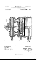
- FIG. 1 a side elevation of a governor embodying my inven tion applied to an ordinary type of governor.
- Fig. 2 is an end elevation of the same, facing -the cylinder.
- Fig. 3 is a vertical central sect-ion longitudinally of the cylinders.
- Fig. t is an end view facing the toothed racks.
- Fig. 5 is a side elevation of a governor embodying my invention, showing one form. of attachment for maintaining the governor-rod neutral or inactive during the return of the balls to a normal position.
- centrifugal weights in connection with duid-filled cylinders as one form of mechanism by which the main gate of the prime motor is to be controlled and shifted to open or close more or less and to be locked in place.
- -In the present instance 2 represents the weights, operated centrifugally in the ordinary manner by means .of the shaft 3 and pulley et to the prime motor, which is supplied by the gate to be controlled.
- These several parts are suitably mounted and assembled on a standard 5, while beneath are arranged two cylinders (5 7 respectively secondary and primary, one above the other with avalve-casin g between them.
- Vertica-lly and centrally of -the regulator-weights is posi- ⁇ tioned a governor-rod 8, adapted to be recip rocated by changes in the position of the weights due to variation in the speed of the prime motor.
- the lower end of said rod is united with a valve Sl, (see Fig. 3,) by which the to-and-fro movements of a piston l() in the secondary cylinder 6 are regulated.
- Said piston isfurnished with a rod 12, which ter- IOO minates in a toothed rack 13.
- the primary cylinder 7 is similarly equipped with a piston 14, having a rod 15, also with a rack 1G.
- One purpose of my invention is to enable the regulator-weigh ts to be easily influenced by slight changes in the speed of the prime motor. Now these elements have little or no active force, and accordingly it would be impossible to operate the main gate of the prime motor, especially of water-wheels, as many such require very powerful agencies to operate them.
- this valve In connection with this valve is a fluid system under any suitable pressure, and this fluid by means of the valve 9 serves to actuate and regulate the travel of the piston 10. As fluid enters on one side an equal quantity is discharged from the opposite end of the cylinder. Hence the piston is constantly held locked except during such intervals as the valve allows circulation to go on.
- the main supply-pipe of this system is at 17, the discharge at 18, and both supply and discharge are common to the two cylinders.
- this secondary piston and its valve is a primary piston and valve, as before premised.
- this piston 14 is to move the gate it is of large area, and its valve 2O is proportioned accordingly.
- Fig. 3 the arrows indica-te the operation of the pistons and their valves.
- the valve 9 has been shifted by the weights and iiuid is now entering the cylinder G at the left end and is discharging from the right end.
- the piston is accordinglyadvancing, as indicated by the arrows.
- valve-casing 28 to the main valve 2O is positioned between the two cylinders, and a tinues to rock until its central point 28 has i advanced sufficiently to open the main valve 20.
- the action of the regulatoi ⁇ veights is to open the secondary valve a short distance for variations in speed and with certain arrangement of part-s, such as are shown in Fig. 5,
- Fig. 5 the gov# is attached to a rack 35, meshing withthe wheel 32.
- Motion ofthe connecting-rods 36 37 to the secondary gate-controller serves to rotate the rod S and stop further travel of the secondary controller,occasioned by the departure of the weights from their normal.
- This stopping of the secondary gate-contro1ler is produced by the endwise thrust of the shaft 34.
- Rotation of the said shaft acts to reversely and slowly revolve the rod 8 and in this way n counteract the action of the weights as they return to the normal, such reverse rotation of the rod S serving to maintain the secondary controller from movement except at proper times. 4
- Figs. 1 and 2 of the drawings my invention is applied to a governor of the usual type in which the governor-rod S is merely designed to reciprocate, while in Fig. 5 my invention is to coperate with a governor in which the rod Sis to have axial rotation as well as the usual
- Ido not wish to be confined to the peculiar land specific elements for controlling and operating the main gate in the form of fluid-filled cylinders with pistons, since other instrumentalities may be assembled in lieu thereof to perform similar functions.
- the gate-controlling mechanism is merely one form, the preferred one, of illustrating my invention.
- Vhat I claim isl.
- a governor comprising weights, a secondary gate-controller operated directlyT by the weights, a primary gate-controller united to the gate, and an intermediary gate-controller operated by the secondary gate-controller, to impart travel to the primary controller, substantially as specified.
- centrifugal governors one or more revolving weights, a gate-shaft, a fixed standard, movable toothed racks therein, and an oscillating toothed wheel to interconnect said racks, combined with primary and secondary gate-controllers, united with the racks, and an intermediary controller, attached to the wheel center, substantially as set forth.
- one or more rotary weights a fixed standard, movable toothed racks in parallelism thereon, a gate-shaft, a toothed sector on said shaft to engage one of the racks, and an oscillating toothed wheel to engage said racks, the points of oscillation being on the racks, combined with a secondary gate-controller connected directly with the weights, a primary gate-controller united to the gate-shaft, and an intermediate gatecontroller, interconnected with the center of the toothed wheel, substantially as explained.
Landscapes
- Engineering & Computer Science (AREA)
- Chemical & Material Sciences (AREA)
- Combustion & Propulsion (AREA)
- Mechanical Engineering (AREA)
- General Engineering & Computer Science (AREA)
- Physics & Mathematics (AREA)
- General Physics & Mathematics (AREA)
- Automation & Control Theory (AREA)
- Fluid-Driven Valves (AREA)
Description
(No Model.) 3 Sheets-Sheet 1.
N. LOMBARD. ATTACHMENT EUR SPEED GovEENoEs.
3 Sheets-Sheet 2.
(No Model.) v v N. LOMBARD.-
ATTACHMENT ron SPEED GovBRNoRs.
No. 587,675. Patented Aug. 3,1897.
l A ll l u] l n l# HI L j b l l 7| j y a m @l I H w' N L l w l i l g. g l
WWA/55555- //\/\/E/\/TU/= Tu: nonms verras w. moruufno. wumcron. nA c.
heets--Sheet 3;
(No Model.)
N.L0MBARD. ATTACHMBNTF'OR SPEED GUVERNORS.
Patented Aug'. 3, 1897.
.J. IQ. F n w M MyW. w nu HIIIIHII EN ad e .W .M if, m. l ..I.l.l-|n. w lill W /m wil i e uw e en o bs. uw lll|| l m .1 NN. QC Aww n -m .mei M e. e f d E w w mc cams gnam co, pHoro-mwa. wnsmnm'ou. DIC.
UNITED STATES PATENT OFFICE.
NATHANIEL LOMBARD, OF BOSTON, MASSACHUSETTS, ASSIGNOR TO THE LOMBARD TVATER THEEL GOVERNOR COMPANY, OF SAME PLACE AND PORTLAND, MANE.
ATTACHMENT FOR SPEED-GOVERNORS.
SPECIFICATION forming part of Letters Patent No. 587,675, dated August 3, 1897.
Application tiled December l5, 1896. Serial No. 615,784. (No model.)
T0 @ZZ whom it may concern:
Be 1t known that I, NATHANIEL LOMBARD,
Va citizen of the United States, residing at Bos-l ton, in the county of Suffolk and State of Massachusetts, have invented certain new and useful Improvements in Attachments for Speed-Governors and I do hereby declare the following to be a full, clear, and exact description of the invention, such as will enable others skilled in the art to which it appertains to make and use the same, reference being had to the accompanying drawings, and to figures of reference marked thereon, which forni a part of this specification.
This invention relates to governors, more particularly such as are designed to control water-wheels.
My invention relates to that class of governors in which the gate-actuating devices comprise a fluid-filled cylinder fitted with a reciprocating piston and a piston-rod, the latter terminating in a toothed rack which is employed to open and close the gate.
My improvements are embodied in the arrangement of parts by which the efficiency of the apparatus is improved and by means of which powerful apparatus may be employed to control the gate and yet at the same time the disadvantages which arise from the use of large valves are overcome.
' My invention is embodied in the arrangement of aprimary gate-actuatin g piston within a cylinder, a valve therefor, and a secondary piston to control the valve to the cylinder of the primary piston, the valve of the secondary piston being governed by the regulator-weights; furthermore, in the use of two toothed sectors or an oscillating toothed wheel which engages the racks attached, respectively, tothe rods of the primary and secondary pistons, and, furthermore, in the manner of uniting the valve-rod of the primary cylinder to the center of the toothed wheel. ln this way a strong leverage is exerted on the primary valve, because when one piston is in motion the other is generally stationary, and as a consequence the part of the toothed wheel in engagement with the rack on the stationary piston is a fixed point while the other corresponding point is rocking. Hence the center of the wheel is reciprocated in right lines and the primary valve, even if of larger area, is readily controlled.
Brie fly described, myinvention is embodied in the combination, with centrifugal weights, of a secondary gate-controller connected directly with the weights, a primary gate-controller united with the gate-shaft, and an intermediary gate-controller which is at stated intervals actuated by both the primary and secondary lcontrollers and by its movements controls the travel of the primary gate-controller.
The drawings represent, in Figure 1, a side elevation of a governor embodying my inven tion applied to an ordinary type of governor. Fig. 2 is an end elevation of the same, facing -the cylinder. Fig. 3 is a vertical central sect-ion longitudinally of the cylinders. Fig. t is an end view facing the toothed racks. Fig. 5 is a side elevation of a governor embodying my invention, showing one form. of attachment for maintaining the governor-rod neutral or inactive during the return of the balls to a normal position.
In the governor herewith illustrated I propose to employ centrifugal weights in connection with duid-filled cylinders as one form of mechanism by which the main gate of the prime motor is to be controlled and shifted to open or close more or less and to be locked in place. -In the present instance 2 represents the weights, operated centrifugally in the ordinary manner by means .of the shaft 3 and pulley et to the prime motor, which is supplied by the gate to be controlled. These several parts are suitably mounted and assembled on a standard 5, while beneath are arranged two cylinders (5 7 respectively secondary and primary, one above the other with avalve-casin g between them. Vertica-lly and centrally of -the regulator-weights is posi-` tioned a governor-rod 8, adapted to be recip rocated by changes in the position of the weights due to variation in the speed of the prime motor. The lower end of said rod is united with a valve Sl, (see Fig. 3,) by which the to-and-fro movements of a piston l() in the secondary cylinder 6 are regulated. Said piston isfurnished with a rod 12, which ter- IOO minates in a toothed rack 13. The primary cylinder 7 is similarly equipped with a piston 14, having a rod 15, also with a rack 1G.
One purpose of my invention is to enable the regulator-weigh ts to be easily influenced by slight changes in the speed of the prime motor. Now these elements have little or no active force, and accordingly it would be impossible to operate the main gate of the prime motor, especially of water-wheels, as many such require very powerful agencies to operate them. Hence I have provided the secondary cylinder 6 with a small valve, and consequentlylittle or no difficulty is had in regulating its movements. In connection with this valve is a fluid system under any suitable pressure, and this fluid by means of the valve 9 serves to actuate and regulate the travel of the piston 10. As fluid enters on one side an equal quantity is discharged from the opposite end of the cylinder. Hence the piston is constantly held locked except during such intervals as the valve allows circulation to go on. The main supply-pipe of this system is at 17, the discharge at 18, and both supply and discharge are common to the two cylinders. In connection with this secondary piston and its valve is a primary piston and valve, as before premised. As this piston 14 is to move the gate it is of large area, and its valve 2O is proportioned accordingly. In Fig. 3 the arrows indica-te the operation of the pistons and their valves. The valve 9 has been shifted by the weights and iiuid is now entering the cylinder G at the left end and is discharging from the right end. The piston is accordinglyadvancing, as indicated by the arrows. This movement has impelled the Valve 2O of the primary cylinder in the same direction, but with the result to cause liquid to enter the right-hand end of the said cylinder and discharge from the lef t-ha nd end, with the result that the main gatey controller or piston 14 is moving oppositely to that of the secondary gate controller or piston 10. In order to interconnect these several instrumentalities, whereby the movement of one shall directly affect the other and at the same time to properly and powerfully operate the main valve 20, I have arranged the following parts: Mounted upon a suitable casting 2l, which constitutes a part of the general support, is an upright standard 23, to which are attached parallel guide-bars 24 24', adapted to receive the toothed racks 13 16. Transversely of said standard is the rocking shaft 25 to the main gate, and this is operated by a toothed sector 26, meshing in the rack 16 of the primary piston. Interconnectin g the two racks 13 16 is a mutilated toothed wheel or two similar sectors 27 27', acting as a unit. Said sectors engage with and are held in position by plates which overlap the guide-bars, and the said wheel is adapted for oscillations.
The valve-casing 28 to the main valve 2O is positioned between the two cylinders, and a tinues to rock until its central point 28 has i advanced sufficiently to open the main valve 20. The action of the regulatoi\veights is to open the secondary valve a short distance for variations in speed and with certain arrangement of part-s, such as are shown in Fig. 5,
and then immediately to close said valve. This closure is produced by the movement of the secondary piston due to the opening of its valve. Consequently when the main valve has opened the secondary valve may be closed or is in the act of closing, and the piston 6 will then become stationary. Consequently the top sector is now a xed point or fulcrum, and the main piston now rocks the sector 27 with the result to close the main valve. Thus it will be seen that for a small movement of a large valve the piston 14 travels a long distance. In some instances where the secondary piston has made a large movement the primary valve' is opened and so continues after the mainpiston has commenced its travel.. At such times both the pistons are in motion simultaneously. The valve 30 is to be used when the regulator is to be sh ut down in case of repairs or otherwise. ernor-rod is to have axial rotation by means of a toothed wheel A shaft 34, arranged to have endwise thrust and likewise rotation,
In Fig. 5 the gov# is attached to a rack 35, meshing withthe wheel 32. Motion ofthe connecting-rods 36 37 to the secondary gate-controller serves to rotate the rod S and stop further travel of the secondary controller,occasioned by the departure of the weights from their normal. This stopping of the secondary gate-contro1ler is produced by the endwise thrust of the shaft 34. Rotation of the said shaft acts to reversely and slowly revolve the rod 8 and in this way n counteract the action of the weights as they return to the normal, such reverse rotation of the rod S serving to maintain the secondary controller from movement except at proper times. 4
It will be seen that the outer extremity of the main-valve rod 29 is secured to the center of the sectors 27 27. Hence the travel of the piston 10 serves to open the main valve, while the motion of the main piston 14 is always tending to close the same.
In Figs. 1 and 2 of the drawings my invention is applied to a governor of the usual type in which the governor-rod S is merely designed to reciprocate, while in Fig. 5 my invention is to coperate with a governor in which the rod Sis to have axial rotation as well as the usual In the application of my invention Ido not wish to be confined to the peculiar land specific elements for controlling and operating the main gate in the form of fluid-filled cylinders with pistons, since other instrumentalities may be assembled in lieu thereof to perform similar functions. In the present instance the gate-controlling mechanism is merely one form, the preferred one, of illustrating my invention.
Vhat I claim isl. A governor comprising weights, a secondary gate-controller operated directlyT by the weights, a primary gate-controller united to the gate, and an intermediary gate-controller operated by the secondary gate-controller, to impart travel to the primary controller, substantially as specified.
2. In regulators, centrifugal weights, a secondary gate-controller operateddirectly by said weights, an intermediary gate-controller, and a main gate-controller, combined with mechanism which interconnects the three controllers, in such manner that activity of the intermediary controller is mutually governed by the primary and secondary controllers, as described.
In water-wheel governors, the combination with one or more centrifugal Weights, of a secondarypiston controlled by the weights, a primary piston, and a piston-valve therefor, combined with mechanism which interconnects said pistons to compel opposite movements of the same, and a rod to unite the piston-valve with the mechanism which centrifugal interconnects said pistons, stated.
4. In centrifugal governors, one or more revolving weights, a gate-shaft, a fixed standard, movable toothed racks therein, and an oscillating toothed wheel to interconnect said racks, combined with primary and secondary gate-controllers, united with the racks, and an intermediary controller, attached to the wheel center, substantially as set forth.
5. In speed-governors, one or more rotary weights, a fixed standard, movable toothed racks in parallelism thereon, a gate-shaft, a toothed sector on said shaft to engage one of the racks, and an oscillating toothed wheel to engage said racks, the points of oscillation being on the racks, combined with a secondary gate-controller connected directly with the weights, a primary gate-controller united to the gate-shaft, and an intermediate gatecontroller, interconnected with the center of the toothed wheel, substantially as explained.
G. In a speed-governor, revoluble Weights, a rack-actuating secondary gate-controller, a
l:.,i'overnor-rod, and a valve operated thereby,
combined with a rack-actuating primary gatecontroller, a toothed gear to interconnect the primary and secondary gate-controllers, an intermediate gate-controller united to the center of the toothed wheel, and mechanism which interconnects the governor-rod with the secondary controller, whereby rotation is imparted to the rod, substantially as described.
In testimony whereof I affix my signature in presence of two witnesses.
NATHANIEL LOMBARD. `Witnesses:
H. E. LODGE,
FRANCIS C. S'rANwooD.A
substantially as
Publications (1)
| Publication Number | Publication Date |
|---|---|
| US587675A true US587675A (en) | 1897-08-03 |
Family
ID=2656343
Family Applications (1)
| Application Number | Title | Priority Date | Filing Date |
|---|---|---|---|
| US587675D Expired - Lifetime US587675A (en) | Attachment for speed-governors |
Country Status (1)
| Country | Link |
|---|---|
| US (1) | US587675A (en) |
-
0
- US US587675D patent/US587675A/en not_active Expired - Lifetime
Similar Documents
| Publication | Publication Date | Title |
|---|---|---|
| US1706812A (en) | Prime-mover-control system | |
| US536156A (en) | Island | |
| US335228A (en) | Assigatob of one-half | |
| US1567666A (en) | Governor | |
| US1088079A (en) | Engine-governor. | |
| US528276A (en) | Engine-governor | |
| US1109153A (en) | Relief mechanism for water-motors. | |
| US261980A (en) | Andebs back | |
| US512411A (en) | Washinqton | |
| US80025A (en) | Samuel stanton | |
| US1583610A (en) | Governing mechanism for prime movers | |
| US774011A (en) | Governor for steam-engines. | |
| US334581A (en) | Centrifugal speed-governor | |
| US690163A (en) | Valve-gear for engines. | |
| US559018A (en) | Reversing valve-gear | |
| US25769A (en) | of rochester | |
| US715961A (en) | Governor. | |
| US594632A (en) | Speed-regulator | |
| US360741A (en) | tonkin | |
| US796518A (en) | Governing mechanism for turbines. | |
| US223930A (en) | Water-motor | |
| US814400A (en) | Governor mechanism for motors. | |
| US1345232A (en) | Valve-gear for reciprocating steam-engines | |
| US167885A (en) | Improvement in governors | |
| US550725A (en) | Valve-gear |