US5875856A - Throttle for a motor driven hammer mechanism - Google Patents
Throttle for a motor driven hammer mechanism Download PDFInfo
- Publication number
- US5875856A US5875856A US08/930,397 US93039797A US5875856A US 5875856 A US5875856 A US 5875856A US 93039797 A US93039797 A US 93039797A US 5875856 A US5875856 A US 5875856A
- Authority
- US
- United States
- Prior art keywords
- lever
- throttle
- transfer device
- motor
- speed
- Prior art date
- Legal status (The legal status is an assumption and is not a legal conclusion. Google has not performed a legal analysis and makes no representation as to the accuracy of the status listed.)
- Expired - Fee Related
Links
- 230000007246 mechanism Effects 0.000 title claims abstract description 13
- 230000008878 coupling Effects 0.000 claims 2
- 238000010168 coupling process Methods 0.000 claims 2
- 238000005859 coupling reaction Methods 0.000 claims 2
- 238000005553 drilling Methods 0.000 description 3
- 238000002485 combustion reaction Methods 0.000 description 1
- 230000003247 decreasing effect Effects 0.000 description 1
Images

Classifications
-
- B—PERFORMING OPERATIONS; TRANSPORTING
- B25—HAND TOOLS; PORTABLE POWER-DRIVEN TOOLS; MANIPULATORS
- B25D—PERCUSSIVE TOOLS
- B25D17/00—Details of, or accessories for, portable power-driven percussive tools
- B25D17/04—Handles; Handle mountings
Definitions
- the present invention relates to a throttle for a motor driven hammer mechanism. More particularly the invention relates to a throttle which allows a simple control of the rotational speed of the motor during collaring.
- the present invention which is defined in the subsequent claims, aims at achieving a throttle where the above mentioned drawbacks have been eliminated through introduction of an extra lever for reducing the rotational speed of the motor during collaring. Because of this the operator can hold the hammer mechanism in a firm grip for guiding the hammer mechanism efficiently and comfortably over the surface to be worked on.
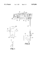
- FIG. 1 shows a schematic view of a hammer mechanism according to the invention.
- FIG. 2 shows a section through one of the handles on the hammer mechanism with the throttle in idle position.
- FIG. 3 shows a section through the handle with the throttle in full speed position.
- the hammer mechanism shown in the drawings which can be a drilling machine and/or a pavement breaker, comprises a machine housing 1 on which two handles 2 are arranged for the handling of the machine. A tool 11 is inserted into the machine. During operation a hammer piston 12 arranged for movement to-and-fro in the hammer mechanism hits the tool.
- a throttle is arranged in one of the handles 2 .
- the throttle comprises a first lever 3 which through a link 13 is swingably connected to the handle 2.
- a second lever 6 is through a link 16 swingably connected to the first lever 3.
- a transfer device 4 in form of a flexible sleeve and a cable 14 arranged therein is arranged to transfer the movement of the second lever to an operating arm 15 of a speed regulator 5 associated with a motor 20 provided in the machine housing 1.
- the motor can be a combustion engine. an electric motor. a hydraulic motor or some other suitable motor.
- the sleeve is at one end connected with the second lever 6 and at the other end with a bracket 19 in the machine housing.
- the cable 14 is at one end connected with the handle 2 and at the other end with the operating arm 15 on the speed regulator 5.
- Cable and sleeve can, of course, be arranged the other way round, i.e. the cable 14 can be connected to the second lever 6 and the sleeve to the handle 2.
- An adjusting screw 8 is arranged on the second lever 6 for adjustment of the maximum swing of the second lever 6 relative to the first lever 3. This swing occurs about the link 16 against the action of the spring 7.
Landscapes
- Engineering & Computer Science (AREA)
- Mechanical Engineering (AREA)
- Percussive Tools And Related Accessories (AREA)
- Electrophonic Musical Instruments (AREA)
- Percussion Or Vibration Massage (AREA)
Abstract
A throttle for a motor driven hammer mechanism has a handle (2) connected to a machine housing (1), a first lever (3) swingably connected to the handle, a second lever (6) swingably connected to the first lever, and a spring (7) arranged between the two levers and a transfer device (4) for transferring the movement of the levers to an operating arm (15) on a speed regulator arranged in the hammer mechanism.
Description
The present invention relates to a throttle for a motor driven hammer mechanism. More particularly the invention relates to a throttle which allows a simple control of the rotational speed of the motor during collaring.
In prior art motor driven hammer mechanisms one has used a lever connected with one of the handles for controlling the rotational speed of the motor. This solution works well during drilling when one works with full motor speed. During collaring, when one works with reduced speed, the prior art throttle is uncomfortable because the lever should be partly pressed down at the same time as the drilling machine should be guided relative to the surface to be worked on.
The present invention, which is defined in the subsequent claims, aims at achieving a throttle where the above mentioned drawbacks have been eliminated through introduction of an extra lever for reducing the rotational speed of the motor during collaring. Because of this the operator can hold the hammer mechanism in a firm grip for guiding the hammer mechanism efficiently and comfortably over the surface to be worked on.
An embodiment of the invention is described below with reference to the accompanying drawings in which FIG. 1 shows a schematic view of a hammer mechanism according to the invention. FIG. 2 shows a section through one of the handles on the hammer mechanism with the throttle in idle position. FIG. 3 shows a section through the handle with the throttle in full speed position.
The hammer mechanism shown in the drawings, which can be a drilling machine and/or a pavement breaker, comprises a machine housing 1 on which two handles 2 are arranged for the handling of the machine. A tool 11 is inserted into the machine. During operation a hammer piston 12 arranged for movement to-and-fro in the hammer mechanism hits the tool. In one of the handles 2 a throttle is arranged. The throttle comprises a first lever 3 which through a link 13 is swingably connected to the handle 2. A second lever 6 is through a link 16 swingably connected to the first lever 3.
Between the levers a spring 7 is arranged to keep the levers apart. Through this the second lever 6 is swung toward an end position relative to the first lever 3. This end position is defined by a stop 31 on the first lever 3. A transfer device 4 in form of a flexible sleeve and a cable 14 arranged therein is arranged to transfer the movement of the second lever to an operating arm 15 of a speed regulator 5 associated with a motor 20 provided in the machine housing 1. The motor can be a combustion engine. an electric motor. a hydraulic motor or some other suitable motor. The sleeve is at one end connected with the second lever 6 and at the other end with a bracket 19 in the machine housing. The cable 14 is at one end connected with the handle 2 and at the other end with the operating arm 15 on the speed regulator 5. Cable and sleeve can, of course, be arranged the other way round, i.e. the cable 14 can be connected to the second lever 6 and the sleeve to the handle 2. An adjusting screw 8 is arranged on the second lever 6 for adjustment of the maximum swing of the second lever 6 relative to the first lever 3. This swing occurs about the link 16 against the action of the spring 7.
With the levers in the positions shown in FIG. 2 the motor idles. In the positions shown in FIG. 3 the motor is operating at full speed. Through pressing down the second lever 6 toward the first lever 3 against the action of the spring 7 the speed of the motor is decreased to a speed suitable for collaring. The rotational speed for collaring is adjusted with the adjusting screw 8. With the throttle according to the invention one can have the first lever completely pressed down during collaring which makes it substantially easier to guide the machine during collaring.
Claims (9)
1. Throttle for a motor driven hammer mechanism comprising a handle (2) connected to a machine housing (1), a first lever (3) swingably coupled to said handle, and a transfer device (4) coupled to said first lever for transferring movement of the position of said first lever to a speed regulator (5) for controlling the speed of the motor, wherein a second lever (6) is disposed between said first lever and said transfer device for swingably coupling said first lever to said transfer device, said transfer device (4) being coupled to said second lever (6) for transferring movement of the position of said second lever to said speed regulator for controlling the speed of the motor independent of said first lever, and a resilient element (7) is arranged between said first (3) and second (6) levers for swinging said second lever (6) toward an end position (31) relative to said first lever (3).
2. Throttle according to claim 1, comprising adjusting means (8) for adjusting the maximum swing of said second lever (6) relative to said first lever (3).
3. Throttle according to claim 2, wherein said adjusting means comprises an adjusting screw (8) arranged on said second lever (6).
4. Throttle according to claim 1, wherein said resilient element comprises a spring.
5. Throttle according to claim 1, wherein said end position (31) is a stop element defined on said first lever (3).
6. Throttle for a motor driven hammer mechanism comprising a handle (2) connected to a machine housing (1), a first lever (3) swingably coupled to said handle, and a transfer device (4) coupled to said first lever for transferring movement of the position of said first lever to a speed regulator (5) for controlling the speed of the motor, wherein a second lever (6) is disposed between said first lever and said transfer device for swingably coupling said first lever to said transfer device, said transfer device (4) being coupled to said second lever (6) for transferring movement of the position of said second lever to said speed regulator for controlling the speed of the motor independent of said first lever, and a resilient element (7) is arranged between said first (3) and second (6) levers.
7. Throttle according to claim 6, comprising adjusting means for adjusting the maximum swing of said second lever (6) relative to said first lever (3).
8. Throttle according to claim 7, wherein said adjusting means comprises an adjusting screw (8) arranged on said second lever (6).
9. Throttle according to claim 6, wherein said resilient element comprises a spring (7).
Applications Claiming Priority (3)
| Application Number | Priority Date | Filing Date | Title |
|---|---|---|---|
| SE9501340A SE503480C2 (en) | 1995-04-11 | 1995-04-11 | Claims for motor-driven percussion |
| SE9501340 | 1995-04-11 | ||
| PCT/SE1996/000337 WO1996032229A1 (en) | 1995-04-11 | 1996-03-18 | Throttle for a motor driven hammer mechanism |
Publications (1)
| Publication Number | Publication Date |
|---|---|
| US5875856A true US5875856A (en) | 1999-03-02 |
Family
ID=20397923
Family Applications (1)
| Application Number | Title | Priority Date | Filing Date |
|---|---|---|---|
| US08/930,397 Expired - Fee Related US5875856A (en) | 1995-04-11 | 1996-03-18 | Throttle for a motor driven hammer mechanism |
Country Status (6)
| Country | Link |
|---|---|
| US (1) | US5875856A (en) |
| EP (1) | EP0820365A1 (en) |
| JP (1) | JPH11503370A (en) |
| AU (1) | AU5350396A (en) |
| SE (1) | SE503480C2 (en) |
| WO (1) | WO1996032229A1 (en) |
Cited By (3)
| Publication number | Priority date | Publication date | Assignee | Title |
|---|---|---|---|---|
| US20050156009A1 (en) * | 2004-01-15 | 2005-07-21 | Gazlay James M. | Nail gun extension kit |
| US20140209656A1 (en) * | 2013-01-30 | 2014-07-31 | Yi-Chang Wu | Nail gun structure |
| US20170101747A1 (en) * | 2015-10-13 | 2017-04-13 | Black & Decker Inc. | Pavement Breaker |
Families Citing this family (1)
| Publication number | Priority date | Publication date | Assignee | Title |
|---|---|---|---|---|
| DE102010038750A1 (en) * | 2010-08-02 | 2012-02-02 | Robert Bosch Gmbh | Electric power tool with lockable rocker switch |
Citations (10)
| Publication number | Priority date | Publication date | Assignee | Title |
|---|---|---|---|---|
| US1809141A (en) * | 1927-12-21 | 1931-06-09 | Ingersoll Rand Co | Handle for rock drills |
| US2138915A (en) * | 1937-03-02 | 1938-12-06 | Ingersoll Rand Co | Rock drill |
| US2349401A (en) * | 1942-01-21 | 1944-05-23 | Milwaukee Electric Tool Corp | Portable electric tool |
| US2350680A (en) * | 1943-02-18 | 1944-06-06 | Jack & Heintz Inc | Control system |
| US3386298A (en) * | 1966-05-11 | 1968-06-04 | Amp Inc | Switch control mechanism |
| US3666027A (en) * | 1970-08-21 | 1972-05-30 | Black & Decker Mfg Co | Handle and trigger construction |
| US3718313A (en) * | 1971-11-17 | 1973-02-27 | Ingersoll Rand Co | Trigger mechanism |
| US3844360A (en) * | 1972-12-18 | 1974-10-29 | Textron Inc | Hand held power tool with duplex handle |
| US5163354A (en) * | 1991-03-25 | 1992-11-17 | Chicago Pneumatic Tool Company | Safety throttle |
| US5749421A (en) * | 1994-02-28 | 1998-05-12 | Atlas Copco Berema Ab | Pneumatic impact breaker |
-
1995
- 1995-04-11 SE SE9501340A patent/SE503480C2/en not_active IP Right Cessation
-
1996
- 1996-03-18 JP JP8530939A patent/JPH11503370A/en active Pending
- 1996-03-18 EP EP96910256A patent/EP0820365A1/en not_active Withdrawn
- 1996-03-18 WO PCT/SE1996/000337 patent/WO1996032229A1/en not_active Ceased
- 1996-03-18 AU AU53503/96A patent/AU5350396A/en not_active Abandoned
- 1996-03-18 US US08/930,397 patent/US5875856A/en not_active Expired - Fee Related
Patent Citations (10)
| Publication number | Priority date | Publication date | Assignee | Title |
|---|---|---|---|---|
| US1809141A (en) * | 1927-12-21 | 1931-06-09 | Ingersoll Rand Co | Handle for rock drills |
| US2138915A (en) * | 1937-03-02 | 1938-12-06 | Ingersoll Rand Co | Rock drill |
| US2349401A (en) * | 1942-01-21 | 1944-05-23 | Milwaukee Electric Tool Corp | Portable electric tool |
| US2350680A (en) * | 1943-02-18 | 1944-06-06 | Jack & Heintz Inc | Control system |
| US3386298A (en) * | 1966-05-11 | 1968-06-04 | Amp Inc | Switch control mechanism |
| US3666027A (en) * | 1970-08-21 | 1972-05-30 | Black & Decker Mfg Co | Handle and trigger construction |
| US3718313A (en) * | 1971-11-17 | 1973-02-27 | Ingersoll Rand Co | Trigger mechanism |
| US3844360A (en) * | 1972-12-18 | 1974-10-29 | Textron Inc | Hand held power tool with duplex handle |
| US5163354A (en) * | 1991-03-25 | 1992-11-17 | Chicago Pneumatic Tool Company | Safety throttle |
| US5749421A (en) * | 1994-02-28 | 1998-05-12 | Atlas Copco Berema Ab | Pneumatic impact breaker |
Cited By (4)
| Publication number | Priority date | Publication date | Assignee | Title |
|---|---|---|---|---|
| US20050156009A1 (en) * | 2004-01-15 | 2005-07-21 | Gazlay James M. | Nail gun extension kit |
| US20140209656A1 (en) * | 2013-01-30 | 2014-07-31 | Yi-Chang Wu | Nail gun structure |
| US20170101747A1 (en) * | 2015-10-13 | 2017-04-13 | Black & Decker Inc. | Pavement Breaker |
| US11739481B2 (en) * | 2015-10-13 | 2023-08-29 | Black & Decker Inc. | Pavement breaker |
Also Published As
| Publication number | Publication date |
|---|---|
| WO1996032229A1 (en) | 1996-10-17 |
| AU5350396A (en) | 1996-10-30 |
| SE9501340L (en) | 1996-06-24 |
| SE503480C2 (en) | 1996-06-24 |
| JPH11503370A (en) | 1999-03-26 |
| SE9501340D0 (en) | 1995-04-11 |
| EP0820365A1 (en) | 1998-01-28 |
Similar Documents
| Publication | Publication Date | Title |
|---|---|---|
| US5145044A (en) | Two-handle arrangement for a handheld portable tool | |
| US7617885B2 (en) | Drill attachment | |
| US5758546A (en) | Hand lever device | |
| CA2122871A1 (en) | Screw gun with a feeder for a screw supply belt | |
| US5871202A (en) | Hand lever apparatus having a toggle mechanism | |
| US4222443A (en) | Motor-driven hammer drill | |
| JP3305157B2 (en) | Hand lever device | |
| US6442841B1 (en) | Device in connection with hand-operated working machine | |
| JPH0914004A (en) | Hand lever device | |
| EP0968641A3 (en) | Operation control lever unit for engine-powered working machine | |
| US6499236B2 (en) | Snow removing machine | |
| US5685271A (en) | Hand lever device | |
| KR100393167B1 (en) | Throttle adjusting apparatus for working machine | |
| US5875856A (en) | Throttle for a motor driven hammer mechanism | |
| US5042626A (en) | Arrangement for actuating a braking device for bringing a motor-driven work tool of a work apparatus to standstill | |
| US4898039A (en) | Throttle lever holding device | |
| US6055797A (en) | Portable power machine having safety mechanism | |
| US3849620A (en) | Deadman control | |
| CN1796760B (en) | Hand-held work implements powered by internal combustion engines | |
| US8272364B2 (en) | Implement having rotational speed reduction and operating method therefor | |
| US5934149A (en) | Hand lever device | |
| JP3483669B2 (en) | Hand lever device | |
| JP4211959B2 (en) | Throttle adjusting device for brush cutter etc. | |
| JP4666824B2 (en) | Engine throttle adjustment device for brush cutters, etc. | |
| CN101126940A (en) | Operating bar device |
Legal Events
| Date | Code | Title | Description |
|---|---|---|---|
| AS | Assignment |
Owner name: ATLAS COPCO BEREMA AB, SWEDEN Free format text: ASSIGNMENT OF ASSIGNORS INTEREST;ASSIGNOR:GUSTAVSSON, MAGNUS;REEL/FRAME:008970/0950 Effective date: 19970916 |
|
| REMI | Maintenance fee reminder mailed | ||
| LAPS | Lapse for failure to pay maintenance fees | ||
| STCH | Information on status: patent discontinuation |
Free format text: PATENT EXPIRED DUE TO NONPAYMENT OF MAINTENANCE FEES UNDER 37 CFR 1.362 |
|
| FP | Lapsed due to failure to pay maintenance fee |
Effective date: 20030302 |