US5875827A - Router table push shoe - Google Patents
Router table push shoe Download PDFInfo
- Publication number
- US5875827A US5875827A US09/051,081 US5108198A US5875827A US 5875827 A US5875827 A US 5875827A US 5108198 A US5108198 A US 5108198A US 5875827 A US5875827 A US 5875827A
- Authority
- US
- United States
- Prior art keywords
- base
- push shoe
- guard
- miter
- router table
- Prior art date
- Legal status (The legal status is an assumption and is not a legal conclusion. Google has not performed a legal analysis and makes no representation as to the accuracy of the status listed.)
- Expired - Fee Related
Links
- 210000001364 upper extremity Anatomy 0.000 claims description 2
- 230000000284 resting effect Effects 0.000 description 2
- 238000003780 insertion Methods 0.000 description 1
- 230000037431 insertion Effects 0.000 description 1
- 238000012986 modification Methods 0.000 description 1
- 230000004048 modification Effects 0.000 description 1
Images


Classifications
-
- B—PERFORMING OPERATIONS; TRANSPORTING
- B27—WORKING OR PRESERVING WOOD OR SIMILAR MATERIAL; NAILING OR STAPLING MACHINES IN GENERAL
- B27B—SAWS FOR WOOD OR SIMILAR MATERIAL; COMPONENTS OR ACCESSORIES THEREFOR
- B27B25/00—Feeding devices for timber in saw mills or sawing machines; Feeding devices for trees
- B27B25/10—Manually-operated feeding or pressing accessories, e.g. pushers
-
- Y—GENERAL TAGGING OF NEW TECHNOLOGICAL DEVELOPMENTS; GENERAL TAGGING OF CROSS-SECTIONAL TECHNOLOGIES SPANNING OVER SEVERAL SECTIONS OF THE IPC; TECHNICAL SUBJECTS COVERED BY FORMER USPC CROSS-REFERENCE ART COLLECTIONS [XRACs] AND DIGESTS
- Y10—TECHNICAL SUBJECTS COVERED BY FORMER USPC
- Y10T—TECHNICAL SUBJECTS COVERED BY FORMER US CLASSIFICATION
- Y10T83/00—Cutting
- Y10T83/02—Other than completely through work thickness
- Y10T83/0304—Grooving
-
- Y—GENERAL TAGGING OF NEW TECHNOLOGICAL DEVELOPMENTS; GENERAL TAGGING OF CROSS-SECTIONAL TECHNOLOGIES SPANNING OVER SEVERAL SECTIONS OF THE IPC; TECHNICAL SUBJECTS COVERED BY FORMER USPC CROSS-REFERENCE ART COLLECTIONS [XRACs] AND DIGESTS
- Y10—TECHNICAL SUBJECTS COVERED BY FORMER USPC
- Y10T—TECHNICAL SUBJECTS COVERED BY FORMER US CLASSIFICATION
- Y10T83/00—Cutting
- Y10T83/647—With means to convey work relative to tool station
- Y10T83/6492—Plural passes of diminishing work piece through tool station
- Y10T83/6499—Work rectilinearly reciprocated through tool station
- Y10T83/6508—With means to cause movement of work transversely toward plane of cut
- Y10T83/6515—By means to define increment of movement toward plane of cut
- Y10T83/6518—By pusher mechanism
- Y10T83/6534—With handle
-
- Y—GENERAL TAGGING OF NEW TECHNOLOGICAL DEVELOPMENTS; GENERAL TAGGING OF CROSS-SECTIONAL TECHNOLOGIES SPANNING OVER SEVERAL SECTIONS OF THE IPC; TECHNICAL SUBJECTS COVERED BY FORMER USPC CROSS-REFERENCE ART COLLECTIONS [XRACs] AND DIGESTS
- Y10—TECHNICAL SUBJECTS COVERED BY FORMER USPC
- Y10T—TECHNICAL SUBJECTS COVERED BY FORMER US CLASSIFICATION
- Y10T83/00—Cutting
- Y10T83/647—With means to convey work relative to tool station
- Y10T83/6584—Cut made parallel to direction of and during work movement
- Y10T83/6608—By rectilinearly moving work carriage
- Y10T83/6614—Pusher engaging rear surface of work
-
- Y—GENERAL TAGGING OF NEW TECHNOLOGICAL DEVELOPMENTS; GENERAL TAGGING OF CROSS-SECTIONAL TECHNOLOGIES SPANNING OVER SEVERAL SECTIONS OF THE IPC; TECHNICAL SUBJECTS COVERED BY FORMER USPC CROSS-REFERENCE ART COLLECTIONS [XRACs] AND DIGESTS
- Y10—TECHNICAL SUBJECTS COVERED BY FORMER USPC
- Y10T—TECHNICAL SUBJECTS COVERED BY FORMER US CLASSIFICATION
- Y10T83/00—Cutting
- Y10T83/647—With means to convey work relative to tool station
- Y10T83/6584—Cut made parallel to direction of and during work movement
- Y10T83/6638—Unattached manual work pusher
-
- Y—GENERAL TAGGING OF NEW TECHNOLOGICAL DEVELOPMENTS; GENERAL TAGGING OF CROSS-SECTIONAL TECHNOLOGIES SPANNING OVER SEVERAL SECTIONS OF THE IPC; TECHNICAL SUBJECTS COVERED BY FORMER USPC CROSS-REFERENCE ART COLLECTIONS [XRACs] AND DIGESTS
- Y10—TECHNICAL SUBJECTS COVERED BY FORMER USPC
- Y10T—TECHNICAL SUBJECTS COVERED BY FORMER US CLASSIFICATION
- Y10T83/00—Cutting
- Y10T83/849—With signal, scale, or indicator
- Y10T83/853—Indicates tool position
- Y10T83/855—Relative to another element
- Y10T83/863—Adjustable guide for traversing tool; e.g., radial saw guide or miter saw guide
Definitions
- the present invention relates to tools and accessories which are used in conjunction with a router table and more particularly to an accessory, such as a push shoe, which enables the operator of a router tool to feed stock to the router bit in a safe manner.
- Push shoes for router tables are generally well known. Normally, an operator of a router table uses either extra stock or other material as a push shoe to press against the stock which is being worked upon in order to properly and safely feed the stock into the router bit. The stock is placed against a fence and is pushed along that fence toward the router bit so the bit can act upon the stock in an even manner. Push shoes are utilized to keep the operator's hands away from the router bit. Extra stock can be used or other appendages which press firmly against the stock to be worked upon and allow the operator to properly feed it to the bit. A problem associated with the push shoes of the prior art, is their inability to allows the operator to adjust the push shoe to varying height and width stock. Additionally, nothing in the prior art provides a router table accessory which allows the operator to combine a miter gauge, bit height measuring tool and dovetail gauge in a single adjustable push shoe.
- the object of the present invention is to provide a router table push shoe that can be adjusted to varying height and width stock, and can also be used as a miter gauge, a depth of bit height reference, a scale to check distance from the router bit to the fence, and a gauge for making thru dovetail joints.
- a router table accessory which enables the operator to properly and safely feed stock to a router bit.
- the push shoe of the present invention enables the operator to adjust the shoe to varying stock width and thickness.
- the push shoe additionally has the ability to provide the operator with a miter gauge, a bit height measuring tool, a scale for use in common routing tasks, and a dovetail gauge.
- the push shoe of the present invention has a miter bar which is stored in the push shoe base while the accessory is used as a push shoe.
- the push shoe has a bottom guard and a side guard which are adjustable in the horizontal and vertical direction respectively in order to compensate for varying stock thickness and height.
- the bottom guard and side guard may be completely removed from the push shoe so that the push shoe may be utilized as a miter gauge.
- the miter bar which has a miter pointer at one distal end, may be removed from the base and affixed to the bottom of the push shoe.
- the push shoe base has an angle of deflection scale which the miter pointer is directed to, indicating to the operator which angle the miter bar is set at.
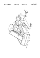
- FIG. 1 is an isometric view of the router table push shoe of the present invention
- FIG. 2 is an isometric view of the router table push shoe of the present invention with the bottom guard removed from the push shoe;
- FIG. 3 is an isometric view of the bottom portion of the router table push shoe and bottom guard of the present invention.
- FIG. 5 is a bottom isometric view of the router table push shoe with a piece of stock inserted for proper feeding to a router bit;
- FIG. 6 is an isometric view of the router table push shoe of the present invention utilized to feed stock on a router table;
- FIG. 7 is an isometric view of the miter bar of the router table push shoe of the present invention.
- FIG. 8 is an isometric view of the router table push shoe of the present invention with the miter bar partially attached;
- FIG. 9 is an isometric view of the router table push shoe of the present invention with the miter bar fully extended;
- FIG. 10 is an isometric view of the side guard removed to act as a bit height measuring tool
- FIG. 11 is an isometric view of one side of the router table push shoe used to measure router bit distance from the fence;
- FIG. 12 is an isometric view of the router table push shoe of the present invention showing use of the dovetail gauge.
- FIG. 13 is a frontal view of the router table push shoe of the present invention showing use of the dovetail gauge.
- FIG. 1 shows the router table push shoe 10 of the present invention.
- the push shoe 10 has an upwardly extending handle 11 which is angled slightly towards the operator and away from the fence 55, as shown in FIG. 13.
- the push shoe of the present invention comes with an adjustable bottom guard 20 removably attached to a base 40, and an adjustable side guard 12 which can be removed and used as a bit height measuring tool. Both the bottom guard 20 and the side guard 12 are adjustable to enable the push shoe 10 to hold thin and narrow stock.
- the push shoe 10 also comes equipped with a miter bar 30, shown in FIG. 1 in the stored position, said miter bar 30 having a miter pointer 31 and an attachment screw 32.
- the horizontally adjustable bottom guard 20 is removably attached to the base 40 via a three wing knob 22.
- the push shoe also has formed in the front right corner a dovetail gauge 17 for making both male and female joints for sliding dovetail joints. All of these attachments allow the push shoe 10 to be used as a push shoe and also as a miter gauge, a depth of bit height reference, a scale to check distance from the router bit to the fence, and a gauge for making 1/2" thru dovetail joints.
- the bottom guard 20 is detachable from the base 40 via a carriage bolt 24.
- the bottom guard 20 has a slot opening 27 allowing for lateral or horizontal adjustment of the bottom guard 20 for both wide and narrow stock.
- the carriage bolt 24 is received into a three wing knob 22.
- the carriage bolt 24 is inserted through the slot opening 27 which is formed in the bottom guard 20.
- the carriage bolt 24 is also inserted through an arc aperture 21 formed in the base 40.
- the slot opening 27 provides for lateral movement of the bottom guard 20 and provides a means for adjusting the bottom guard 20 for varying width stock.
- the bottom guard 20 has raised channel engaging members 25 and 26 configured to fit into receptive recesses 61 and 62, shown in FIG. 3, formed in the underside of the base 40.
- the channel engaging members 25 and 26 allow the bottom guard 20 to slide laterally allowing work-pieces or stock to abut next to the bottom guard 20 directly below a scale 18, as shown in FIG. 5 and 6.
- the three wing knob 22 allows for easy adjustment of the bottom guard 20 for such lateral movement.
- the bottom guard 20 is adjusted to allow stock to abut against a first side 28 of the bottom guard 20.
- Recess members 61 and 62 form a channel for receiving raised the channel engaging members 25 and 26 formed on the bottom guard 20.
- the base 40 provides an upper surface for engaging stock manipulated by the push shoe 10.
- the bottom guard 20 can slide laterally up to one half inch (1/2") providing a full one inch area to hold wider stock.
- FIG. 3 Also shown in FIG. 3 is a corner receiving joint 41 for receiving the back leg of the side guard 12.
- the side guard 12, shown in FIG. 4, is vertically moveable via a round knob 13 which is received within a nut 16 located within a slot 63.
- the side guard 12 is vertically adjustable for differing thickness stock.
- the side guard 12 may be fully removed from the base 40 by removing the knob 13 and the nut 16.
- the side guard 12 is placed adjacent to the back corner of the push shoe 10 so that the back leg of the side guard fits within the corner receiving joint 41 of the push shoe 10.
- the front leg of the side guard 12 is placed against a recessed side portion 44, shown in FIG. 4, formed in the side of the push shoe 10 for receiving the side guard 12.
- the nut 16 is placed within a receiving slot 63 which impedes the rotation of the nut 16 when the round knob 13 is turned.
- the receiving slot 63 therefore is slightly larger in diameter than the nut 16 allowing the nut to drop within the receiving slot 63 in order to properly engage the threaded knob 13.
- the round knob 13 is inserted into a vertical slot 14 in the side guard and a through hole 43 in the base in order to properly secure the knob 13 into the threaded nut 16.
- the side guard 12 also has a recessed channel slot 65 for receiving a channel engaging member 64 formed on a second side of the push shoe 10.
- the channel engaging member 64 and the recessed channel slot 65 allow the side guard to move vertically upon loosening of the round knob 63. There is formed, therefore, a track for side guard 12 to move up and down on.
- the side guard 12 is adjustable for varying thickness stock. If thin stock is to be manipulated by the push shoe, the knob 13 is loosened and the side guard 12 is moved to the upward most position. The side guard may be adjusted for thicker stock by lowering the side guard to the appropriate level. This adjustable side guard provides means for vertically adjusting the push shoe for varying size stock to be manipulated by the router bit.
- the side guard 12 and the bottom guard 20 have been adjusted to receive stock 19.
- the stock 19 abuts along its side against the bottom guard 20 and at its back against the side guard 12.
- the base 40 forms the upper contact surface against which the stock 19 rests upon.
- the push shoe 10 is then utilized to push the stock 19 directly forward without any sideways or lateral movement of the stock against a router bit.
- the bottom guard 20 has been properly adjusted via the carriage bolt 24 and the slot opening 27.
- the side guard 12 has been adjusted to the proper thickness via the knob 13 such that the height and thickness of the stock is matched by the push shoe guards 12, 20 and the base 40.
- the push shoe 10 is utilized to push the stock 19 against a router bit (not shown).
- the stock 19 is pushed along the fence 51 by the push shoe 10.
- the push shoe 10 is held by the operator by a handle 11 which is placed at an appropriate angle leaning towards the operator in order to ease its use and prevent an awkward holding angle by the operator.
- the side guard 12 is adjusted as previously shown.
- the stock 19 is pushed forward to be worked upon by the router bit in a secure and safe manner.
- the push shoe 10 also has stored in the base 40 a miter bar 30 which has located at one end a miter pointer 31.
- the miter bar 30 slides onto the base 40 under lip members 45, 46, shown in FIG. 4. In the fully stored position, the miter bar 30 rests against a U-shaped end support channel 47 at the back end of the push shoe and a flat front support 48 at the front most position. The miter bar 30 is prevented from moving vertically by the lip members 45, 46.
- the miter bar 30 is shown in the stored position in FIG. 1 and FIG. 6.
- the push shoe 10 may alternatively be utilized as a miter pointer.
- the side guard 12 and the bottom guard 20 must be fully removed to use the miter bar 30.
- the unassembled miter bar 30 is shown in FIG. 7.
- a bolt 32 holds the miter pointer 31 to the bar 30 via a nut 33.
- the miter pointer 31 has a locking member 38 which fits into an opening 34 formed in the bar 30.
- a rotation pin 36 is provided for rotating the miter bar 30 about a central point under the push shoe.
- the rotation pin 36 is inserted into an aperture 49 formed on the underside of the push shoe 10, shown in FIG. 3, but only after removal of the bottom guard 20.
- the miter pointer 31 is inserted into a curved or arc opening 37 formed in the base 40 as shown in FIG. 8.
- the miter bar 30 is directed forward while inserting the pointer 31 through an insertion opening located within the curved opening 37.
- the miter bar 30 is then rotated about the rotation pin 36 until a desired angle, which is shown along the curved opening 37 and pointed to by the miter pointer 32, as shown in FIG. 9, is reached.
- the carriage bolt 24 and the three wing knob 22 received through an opening 35 in the bar 30 and through the arcuate aperture 21 formed in the base, are utilized to secure the miter bar 30 at the desired angle.
- the push shoe can then be used as a router table miter gauge which is fully adjustable between a 90° span, 45° in one direction off center and 45° in the opposite direction.
- the side fence 12 may be removed from the push shoe 10 and used as a bit height gauge as shown in FIG. 10. Once removed, the side guard 12 must be inverted so that the numbers are right side up. The side fence may then be used to measure the router bit height, as shown.
- the scale 18 may be used to measure the router table fence offset distance.
- the push shoe 10 thus has means for measuring the offset distance between the fence 51 and the router bit 50 accurately using the scale 18 as shown.
- the push shoe 10 has formed in the base 40 a dovetail gauge 17 as shown in FIG. 12.
- the dovetail gauge 17 is designed for 1/2 inch sliding dovetail joints to be made on a router table.
- the gauge 17 is designed for use on 3/4 inch thick stock when making the male (tenon) portion of the joint. If the stock is not 3/4 inch thick, the router table fence will have to be adjusted to make the joint fit together correctly.
- the side guard 12 To use the push shoe to create the female (mortise) portion of the joint, the side guard 12 must be placed in the fully up position so that the push shoe is resting on the bottom guard 20.
- the dovetail gauge 17 must then be placed over the router bit 50 and the bit raised until it touches the top of the dovetail gauge 17 as shown in FIG. 12. The female portion of the joint may now be cut by pushing the stock forward against the bit.
- the side guard 12 To utilize push shoe 10 to cut the male portion of the joint, the side guard 12 must be placed in the fully up position so that the push shoe is resting on the bottom guard 20. The push shoe is then positioned over the dovetail bit 54 as shown in FIG. 13. The dovetail bit 54 is then raised so that it touches the top and side of the gauge, and the fence 55 is moved so that it touches the side of the shoe as shown in FIG. 13. The male portion of the joint may now be cut matching the female portion of the joint formed as previously described.
Landscapes
- Life Sciences & Earth Sciences (AREA)
- Engineering & Computer Science (AREA)
- Mechanical Engineering (AREA)
- Wood Science & Technology (AREA)
- Forests & Forestry (AREA)
- Footwear And Its Accessory, Manufacturing Method And Apparatuses (AREA)
Abstract
Description
Claims (14)
Priority Applications (1)
| Application Number | Priority Date | Filing Date | Title |
|---|---|---|---|
| US09/051,081 US5875827A (en) | 1996-10-25 | 1996-10-25 | Router table push shoe |
Applications Claiming Priority (2)
| Application Number | Priority Date | Filing Date | Title |
|---|---|---|---|
| US09/051,081 US5875827A (en) | 1996-10-25 | 1996-10-25 | Router table push shoe |
| PCT/US1996/016821 WO1997017175A2 (en) | 1995-10-27 | 1996-10-25 | Router table push shoe |
Publications (1)
| Publication Number | Publication Date |
|---|---|
| US5875827A true US5875827A (en) | 1999-03-02 |
Family
ID=21969212
Family Applications (1)
| Application Number | Title | Priority Date | Filing Date |
|---|---|---|---|
| US09/051,081 Expired - Fee Related US5875827A (en) | 1996-10-25 | 1996-10-25 | Router table push shoe |
Country Status (1)
| Country | Link |
|---|---|
| US (1) | US5875827A (en) |
Cited By (21)
| Publication number | Priority date | Publication date | Assignee | Title |
|---|---|---|---|---|
| USD472166S1 (en) | 2002-01-23 | 2003-03-25 | Swan Richard E | Dovetail gauge |
| WO2003061922A1 (en) * | 2002-01-17 | 2003-07-31 | Henry Wang | Straddle safety pusher system |
| US20050092152A1 (en) * | 2003-10-30 | 2005-05-05 | Woodworker's Supply Inc. | Push block having retractable heel |
| US20060123961A1 (en) * | 2004-11-23 | 2006-06-15 | Norston Fontaine | Offset push stick |
| US20060185485A1 (en) * | 2001-06-01 | 2006-08-24 | Henry Wang | Straddle safety pusher system |
| US20060266174A1 (en) * | 2005-05-13 | 2006-11-30 | Dennis Rowe | Annular octagonal hand held pushing tool for use with cutting and abrasive tools |
| US7260897B1 (en) | 2006-03-28 | 2007-08-28 | Neff Leslie A | Lock miter gauge |
| US7989718B1 (en) | 2009-05-08 | 2011-08-02 | Weber Eugene A | Power control engagement device for a power tool |
| USD665638S1 (en) * | 2011-10-31 | 2012-08-21 | Rockler Companies, Inc. | Push block |
| US20140260866A1 (en) * | 2013-03-15 | 2014-09-18 | Micro Jig, Inc. | Push block for a woodworking apparatus |
| US9199390B2 (en) * | 2013-03-15 | 2015-12-01 | Micro Jig, Inc. | Push block for a woodworking apparatus |
| US20150343586A1 (en) * | 2014-05-27 | 2015-12-03 | The Boeing Company | Table saw guide and safety guard |
| US9227337B2 (en) | 2013-03-15 | 2016-01-05 | Micro Jig, Inc. | Push block for a woodworking apparatus |
| US10011037B2 (en) | 2014-04-14 | 2018-07-03 | Henry Wang | Selectively adjustable heel member for a push block and a push block with the same |
| US10449688B2 (en) * | 2016-08-20 | 2019-10-22 | D. Keith Bow | Workpiece tool and guide |
| USD909837S1 (en) * | 2019-11-15 | 2021-02-09 | Nomis Llc | Push block |
| USD914474S1 (en) * | 2019-12-04 | 2021-03-30 | Nomis Llc | Push block |
| US11261253B2 (en) | 2013-03-01 | 2022-03-01 | Albert Einstein College Of Medicine | HHLA2 as a novel inhibitor of human immune system and uses thereof |
| US11465312B1 (en) | 2022-04-08 | 2022-10-11 | Henry Wang | Coded push block |
| US11731306B1 (en) | 2022-11-08 | 2023-08-22 | Henry Wang | Push block safe index scale |
| US12427691B1 (en) | 2025-04-25 | 2025-09-30 | Henry Wang | Pushblock with compressible heel |
Citations (6)
| Publication number | Priority date | Publication date | Assignee | Title |
|---|---|---|---|---|
| US278815A (en) * | 1883-06-05 | G-age slide for rotary cutters | ||
| US2771920A (en) * | 1955-04-25 | 1956-11-27 | Ambelang Friedrich Wil Hermann | Feeding device for the workpiece on planing machines |
| US2777485A (en) * | 1954-06-04 | 1957-01-15 | Benjamin J Farrow | Means for cutting uniformly spaced tenons |
| US3606916A (en) * | 1969-09-30 | 1971-09-21 | Mildred M Day | Gauge apparatus and method for cutting uniformly spaced routered tenons and mortises |
| US4370909A (en) * | 1981-03-06 | 1983-02-01 | Jennings G Craig | Hand guard for table mounted cutting tool |
| US4485711A (en) * | 1982-09-02 | 1984-12-04 | Shopsmith, Inc. | Adjustable straddle block |
-
1996
- 1996-10-25 US US09/051,081 patent/US5875827A/en not_active Expired - Fee Related
Patent Citations (6)
| Publication number | Priority date | Publication date | Assignee | Title |
|---|---|---|---|---|
| US278815A (en) * | 1883-06-05 | G-age slide for rotary cutters | ||
| US2777485A (en) * | 1954-06-04 | 1957-01-15 | Benjamin J Farrow | Means for cutting uniformly spaced tenons |
| US2771920A (en) * | 1955-04-25 | 1956-11-27 | Ambelang Friedrich Wil Hermann | Feeding device for the workpiece on planing machines |
| US3606916A (en) * | 1969-09-30 | 1971-09-21 | Mildred M Day | Gauge apparatus and method for cutting uniformly spaced routered tenons and mortises |
| US4370909A (en) * | 1981-03-06 | 1983-02-01 | Jennings G Craig | Hand guard for table mounted cutting tool |
| US4485711A (en) * | 1982-09-02 | 1984-12-04 | Shopsmith, Inc. | Adjustable straddle block |
Cited By (28)
| Publication number | Priority date | Publication date | Assignee | Title |
|---|---|---|---|---|
| US7540224B2 (en) | 2001-06-01 | 2009-06-02 | Henry Wang | Straddle safety pusher system |
| US7040206B2 (en) | 2001-06-01 | 2006-05-09 | Micro Jig, Inc. | Straddle safety pusher system |
| US20060185485A1 (en) * | 2001-06-01 | 2006-08-24 | Henry Wang | Straddle safety pusher system |
| WO2003061922A1 (en) * | 2002-01-17 | 2003-07-31 | Henry Wang | Straddle safety pusher system |
| USD472166S1 (en) | 2002-01-23 | 2003-03-25 | Swan Richard E | Dovetail gauge |
| US20050092152A1 (en) * | 2003-10-30 | 2005-05-05 | Woodworker's Supply Inc. | Push block having retractable heel |
| US7886641B2 (en) * | 2003-10-30 | 2011-02-15 | Woodworker's Supply Inc. | Push block having retractable heel |
| US20060123961A1 (en) * | 2004-11-23 | 2006-06-15 | Norston Fontaine | Offset push stick |
| US20060266174A1 (en) * | 2005-05-13 | 2006-11-30 | Dennis Rowe | Annular octagonal hand held pushing tool for use with cutting and abrasive tools |
| US7146890B1 (en) | 2005-05-13 | 2006-12-12 | Dennis Rowe | Annular octagonal hand held pushing tool for use with cutting and abrasive tools |
| US7260897B1 (en) | 2006-03-28 | 2007-08-28 | Neff Leslie A | Lock miter gauge |
| US7989718B1 (en) | 2009-05-08 | 2011-08-02 | Weber Eugene A | Power control engagement device for a power tool |
| USD665638S1 (en) * | 2011-10-31 | 2012-08-21 | Rockler Companies, Inc. | Push block |
| US11261253B2 (en) | 2013-03-01 | 2022-03-01 | Albert Einstein College Of Medicine | HHLA2 as a novel inhibitor of human immune system and uses thereof |
| US9199390B2 (en) * | 2013-03-15 | 2015-12-01 | Micro Jig, Inc. | Push block for a woodworking apparatus |
| US20140260866A1 (en) * | 2013-03-15 | 2014-09-18 | Micro Jig, Inc. | Push block for a woodworking apparatus |
| US9227337B2 (en) | 2013-03-15 | 2016-01-05 | Micro Jig, Inc. | Push block for a woodworking apparatus |
| US20160023371A1 (en) * | 2013-03-15 | 2016-01-28 | Micro Jig, Inc. | Push block for a woodworking apparatus |
| US9707694B2 (en) * | 2013-03-15 | 2017-07-18 | Micro Jig, Inc. | Push block for a woodworking apparatus |
| US10011037B2 (en) | 2014-04-14 | 2018-07-03 | Henry Wang | Selectively adjustable heel member for a push block and a push block with the same |
| US9718209B2 (en) * | 2014-05-27 | 2017-08-01 | The Boeing Company | Table saw guide and safety guard |
| US20150343586A1 (en) * | 2014-05-27 | 2015-12-03 | The Boeing Company | Table saw guide and safety guard |
| US10449688B2 (en) * | 2016-08-20 | 2019-10-22 | D. Keith Bow | Workpiece tool and guide |
| USD909837S1 (en) * | 2019-11-15 | 2021-02-09 | Nomis Llc | Push block |
| USD914474S1 (en) * | 2019-12-04 | 2021-03-30 | Nomis Llc | Push block |
| US11465312B1 (en) | 2022-04-08 | 2022-10-11 | Henry Wang | Coded push block |
| US11731306B1 (en) | 2022-11-08 | 2023-08-22 | Henry Wang | Push block safe index scale |
| US12427691B1 (en) | 2025-04-25 | 2025-09-30 | Henry Wang | Pushblock with compressible heel |
Similar Documents
| Publication | Publication Date | Title |
|---|---|---|
| US5875827A (en) | Router table push shoe | |
| US7658214B2 (en) | Dust collection chute for a jig apparatus | |
| US7819146B2 (en) | Jig apparatus | |
| US4155383A (en) | Router accessory | |
| US5816300A (en) | Woodworking jig | |
| US5890524A (en) | Router table sled | |
| US7857020B2 (en) | Jig apparatus | |
| US6732623B1 (en) | Safety push tool for table mounted cutting tool having an adjustable heel | |
| US20020174755A1 (en) | Work piece guiding system for a table saw | |
| US5979283A (en) | Miter guide | |
| US5038490A (en) | Ceramic tile gauge | |
| US11845135B2 (en) | Miter gauge assembly | |
| US4658686A (en) | Miter gage | |
| US5016358A (en) | Guide fence and mitre guide assembly for router mounting table | |
| US7040206B2 (en) | Straddle safety pusher system | |
| US5513437A (en) | Dovetail tenon offset caliper and dovetail tenon construction method | |
| US20050051238A1 (en) | Micro-adjustment device for the angle stop plank of a planer | |
| US5174553A (en) | Adjustable lock mechanism | |
| WO1997017175A2 (en) | Router table push shoe | |
| US20030209121A1 (en) | Clamping and guiding device for working table | |
| EP2117770B1 (en) | Jig apparatus | |
| CA2512127C (en) | Jig apparatus |
Legal Events
| Date | Code | Title | Description |
|---|---|---|---|
| AS | Assignment |
Owner name: CREDO TOOL COMPANY, OREGON Free format text: ASSIGNMENT OF ASSIGNORS INTEREST;ASSIGNORS:BRUTSCHER, DAVID T.;SPIEGELHALTER, JOHN P.;REEL/FRAME:009265/0112;SIGNING DATES FROM 19980520 TO 19980522 |
|
| REMI | Maintenance fee reminder mailed | ||
| FPAY | Fee payment |
Year of fee payment: 4 |
|
| SULP | Surcharge for late payment | ||
| FEPP | Fee payment procedure |
Free format text: PAYOR NUMBER ASSIGNED (ORIGINAL EVENT CODE: ASPN); ENTITY STATUS OF PATENT OWNER: LARGE ENTITY |
|
| AS | Assignment |
Owner name: CREDO TECHNOLOGY CORPORATION, DELAWARE Free format text: ASSIGNMENT OF ASSIGNORS INTEREST;ASSIGNOR:ROBERT BOSCH TOOL CORPORATION;REEL/FRAME:014615/0215 Effective date: 20030101 Owner name: ROBERT BOSCH TOOL CORPORATION, KENTUCKY Free format text: COMBINED MERGER AND CHANGE OF NAME;ASSIGNOR:VERMONT AMERICAN CORPORATION;REEL/FRAME:014609/0574 Effective date: 20021227 Owner name: VERMONT AMERICAN CORPORATION, DELAWARE Free format text: MERGER;ASSIGNOR:CREDO TOOL COMPANY;REEL/FRAME:014609/0549 Effective date: 20021227 |
|
| REMI | Maintenance fee reminder mailed | ||
| LAPS | Lapse for failure to pay maintenance fees | ||
| STCH | Information on status: patent discontinuation |
Free format text: PATENT EXPIRED DUE TO NONPAYMENT OF MAINTENANCE FEES UNDER 37 CFR 1.362 |
|
| FP | Lapsed due to failure to pay maintenance fee |
Effective date: 20070302 |